

Translate this page into:
3D printing and continuous flow chemistry technology to advance pharmaceutical manufacturing in developing countries
⁎Corresponding author. Paul.Watts@mandela.ac.za (Paul Watts)
-
Received: ,
Accepted: ,
This article was originally published by Elsevier and was migrated to Scientific Scholar after the change of Publisher.
Peer review under responsibility of King Saud University.
Abstract
The realization of a downward spiralling of diseases in developing countries requires them to become self-sufficient in pharmaceutical products. One of the ways to meet this need is by boosting the local production of active pharmaceutical ingredients and embracing enabling technologies. Both 3D printing and continuous flow chemistry are being exploited rapidly and they are opening huge avenues of possibilities in the chemical and pharmaceutical industries due to their well-documented benefits. The main barrier to entry for the continuous flow chemistry technique in low-income settings is the cost of set-up and maintenance through purchasing of spare flow reactors. This review article discusses the technical considerations for the convergence of state-of-the-art technologies, 3D printing and continuous flow chemistry for pharmaceutical manufacturing applications in developing countries. An overview of the 3D printing technique and its application in fabrication of continuous flow components and systems is provided. Finally, quality considerations for satisfying regulatory requirements for the approval of 3D printed equipment are underscored. An in-depth understanding of the interrelated aspects in the implementation of these technologies is crucial for the realization of sustainable, good quality chemical reactionware.
Keywords
Affordable
Continuous flow chemistry
Developing countries
3D printing
Pharmaceutical manufacturing
Quality control

1 Introduction
The sobering reality of limited access to good quality and affordable medicines, characteristic of developing countries, requires innovative and sustainable efforts to bolster the manufacturing capacity of the local pharmaceutical industry. Developing countries over rely on the importation of active pharmaceutical ingredients (APIs) from the Asian and European market. Consequently, medicines are inaccessible to most patients due to high costs and unguaranteed supply chains, as most patients in developing countries fall in the low-middle income bracket, which exerts a huge health burden developing countries. Furthermore, due to over reliance on importation, developing countries are left more exposed and vulnerable in the face of pandemics that disturb supply chains such as the current Severe Acute Respiratory Syndrome Coronavirus 2 (SARS-CoV-2) infection (COVID19) (Cai et al., 2020; Sharma et al., 2020). The alleviation of disease burden in developing countries requires them to become self-sufficient in pharmaceutical products. One of the ways to meet this need is by boosting the local production of APIs and embracing enabling technologies.
Emerging disruptive manufacturing technologies are worth pursuing however, it is pertinent to fully understanding how best to utilize them without compromising on the quality of the product manufactured, particularly for the highly regulated pharmaceutical industry. Continuous flow synthesis, also known as flow chemistry technology is an innovative technology in which chemical reactions are performed in continuous flowing streams within narrow channels (Baumann et al., 2020; Hest and Rutjes, 2020; Ley et al., 2020). Its use in academia, and the chemical and pharmaceutical industry has rapidly grown over the last decade due to its well documented benefits (Akwi and Watts, 2018; Baumann et al., 2020; Britton and Raston, 2017; Hest and Rutjes, 2020; Scotti et al., 2019; Trojanowicz, 2020). The intrinsic properties of continuous flow reactors such as high surface-to-volume ratio enable efficient mixing and accurate control of reaction parameters such as temperature and pressure (Scotti et al., 2019). In addition to lower reaction volumes and rapid heat dissipation, these features make the technology inherently safer than batch reactors (Sagandira and Watts, 2019; Scotti et al., 2019). Continuous flow synthesis enhances selectivity, purity and yield as a result of the suppression of side reactions usually caused by poor mixing and poor heat-transfer, which is common in batch reactors (Akwi and Watts, 2018; Scotti et al., 2019). Previously forbidden chemistry in batch can be performed in continuous flow reactors (Sagandira and Watts, 2020, 2019; Scotti et al., 2019; Trojanowicz, 2020). Although single-step synthesis is common in flow, multi-step synthesis where molecular complexity is accrued through sequential transformations is more valuable and has immensely improved chemical synthesis (Hughes, 2018; Trojanowicz, 2020). The technology has a smaller footprint and is characterised by easier process scale-up from the laboratory to large scale manufacture compared to batch manufacturing (Sagandira and Watts, 2019; Scotti et al., 2019). Inline workup systems such as liquid-liquid separators, gas-liquid separators or solid phase scavenger columns and inline reaction monitoring and analysis using instruments such as mass spectrometry, NMR spectroscopy, liquid chromatography and UV–Vis spectroscopy can be integrated in continuous flow systems (Baumann et al., 2020; Scotti et al., 2019; Trojanowicz, 2020). Interestingly, the pharmaceutical industry is also taking advantage of the technology to develop efficient processes that deliver on the ambitious timelines set in the industry (Baumann et al., 2020; Bogdan and Dombrowski, 2019; Hest and Rutjes, 2020; Porta et al., 2016; Riley et al., 2019). Along with the use of other enabling technologies such as machine learning and artificial intelligence, a future-proof, fully automated industrial manufacturing system for chemicals and active pharmaceutical ingredients is a possibility (Badman et al., 2019; Baumann et al., 2020; Bogdan and Dombrowski, 2019; Fitzpatrick et al., 2016; Ley et al., 2020; Porta et al., 2016; Riley et al., 2019; Trojanowicz, 2020). Owing to all these advantages, novel processing windows, cleaner, more robust, more efficient, less consumptive and safer chemical processes are achievable in flow chemistry (Akwi and Watts, 2018; Baumann et al., 2020; Britton and Raston, 2017; Hest and Rutjes, 2020; Sagandira and Watts, 2020, 2019; Scotti et al., 2019; Trojanowicz, 2020).
Although the importance of pharmaceutical manufacturing innovation in ensuring sustained, reliable and cost effective access to medicine can never be overemphasised, the highly regulated pharmaceutical industry is often conservative in its approach to manufacturing innovation, consequently causing delays to approval (Badman et al., 2019). As rightly stated by Badman et al. (2019), government intervention is necessary in terms of regulatory incentives to overcome the approval time delays. A considerable percentage of pharmaceutical manufacturing in the world is done in China and India. Most production is currently done using batch technology at different sites which is usually accompanied by lead times of up to 12 months (Maier et al., 2020a,b). To keep up with the ever-increasing demand for pharmaceuticals and ensure constant supply chains, pharmaceutical companies and regulatory bodies are embracing continuous manufacturing technology owing to its advantages (Maier et al., 2020a,b). Despite these invaluable advantages associated with this technology, its adoption in countries with well-established pharmaceutical manufacturing industries is still slow due to its disruptive nature (de Souza and Watts, 2017; Riley et al., 2019; Sagandira et al., 2020). In contrast, the technology is less disruptive in developing countries because of the under-developed pharmaceutical industries (de Souza and Watts, 2017; Riley et al., 2019; Sagandira et al., 2020). As a result, these countries are in an unique position to adopt continuous flow manufacturing with less hindrance, besides the cost of setting up the infrastructure. Continuous flow manufacturing has made a remarkable impact in the pharmaceutical industry and setting it up remains more affordable than batch manufacturing (Aguiar et al., 2019; Carneiro et al., 2015; Chada et al., 2017; Dalla-Vechia et al., 2013; de Souza et al., 2018; de Souza and Watts, 2017; Leão et al., 2015; Lima et al., 2020; Mandala et al., 2017; Miranda et al., 2019; Pinho et al., 2014; Riley et al., 2019; Sagandira et al., 2020; Sagandira and Wattts, 2020; Suveges et al., 2018, 2017). Although numerous laboratories build homemade continuous flow systems from commercially available parts or components to address the affordability challenges associated with acquiring the expensive commercial continuous flow systems, these commercial parts or components such as reactors are still out of reach of most chemical laboratories (Britton and Raston, 2017; Penny et al., 2019; Riley et al., 2019). 3D printing (3DP), also known as additive manufacturing (AM), has emerged as an enabling and cost-effective technology in the production of continuous flow components and systems with complex geometries and intricate internal structures. Most importantly, it is accompanied by exceptional design freedom which is not currently available when using the existing microreactor fabrication methods. Further, it exhibits a low carbon footprint (Capel et al., 2013; Dragone et al., 2013; Harding et al., 2020; Rossi et al., 2018). Most recently, Maier et al. (2020a,b) demonstrated the high potential of 3DP technology for cost- and time-efficient production of custom-made continuous flow reactors, applicable for the synthesis of APIs (Maier et al., 2020a,b). Similarly, developing countries can take advantage of 3DP to manufacture continuous flow equipment to enable cost-effective development of continuous flow manufacturing capability. Herein, we review 3DP technology and continuous flow technology as converging technologies in academic and industrial pharmaceutical laboratories towards the realization of affordable and good quality continuous flow components and system that can be utilised in local manufacturing capacity development of pharmaceuticals in developing countries. The specific details of the various 3DP techniques are outside the scope of this review.
2 3D printing and flow chemistry technology convergence
2.1 3D printing technology
3DP is currently one of the most disruptive technologies with immense potential of revolutionising science. It is a process of producing 3D physical objects through successive layering of material from scientific ideas and virtual concepts (Capel et al., 2013; Halada and Clayton, 2018; Neumaier et al., 2019; Rossi et al., 2020, 2018, 2015; Sing et al., 2019). It has gained traction in many fields such as regenerative medicine, chemical industry, dentistry and odontology, architecture, aeronautics, construction and jewellery industry (Aimar et al., 2019; Awad et al., 2018; Halada and Clayton, 2018; Ko et al., 2017; Rashid, 2019; Rossi et al., 2020, 2018; Sing et al., 2019). In 3DP, virtual concepts designed by computer aided design (CAD) are printed into bespoke low-cost solid objects layer-by-layer. The CAD virtual idea is converted to standard tessellation language format (STL) where the 3D surface geometry is described. This geometry subsequently undergoes “slicing” to afford the printable format of 3D model (G-code file), which is subsequently sent to the 3D printer. Many other technical parameters such as size, material, orientation and temperature are considered prior to 3DP into a 3D physical object (Aimar et al., 2019; Awad et al., 2018; Ko et al., 2017; Rashid, 2019; Rossi et al., 2020, 2018). There are various 3DP techniques such as multijet printing (MJP), selective laser sintering (SLS), laminated object manufacturing (LOM), stereolithography (SLA) and fused deposition modelling (FDM). A generic 3DP process sequence is illustrated in Fig. 1.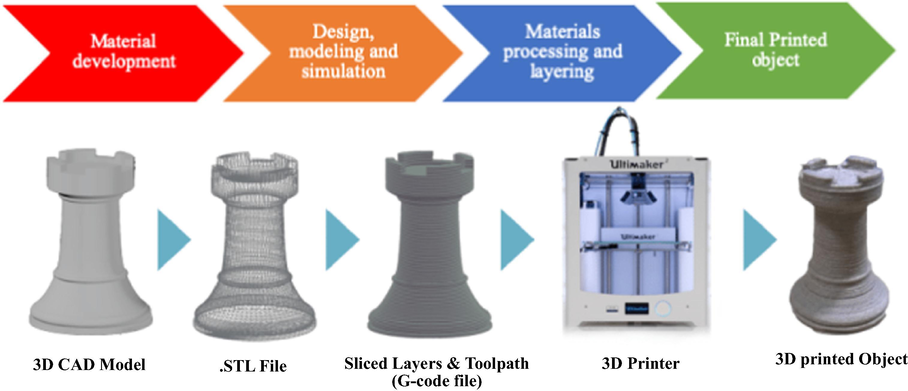
The generic 3D printing process sequence.
2.2 Application of 3D printed continuous flow components and systems
Among other applications in the chemical and pharmaceutical industry, 3DP technique has been used to produce affordable reactionware (He et al., 2016; Kitson et al., 2016; Rossi et al., 2020, 2018, 2015). In recent years, it has been applied in flow chemistry technology; another emerging technology in the chemical and pharmaceutical industry to afford low-cost complex and intricate continuous flow components and systems (Dragone et al., 2013; Harding et al., 2020; He et al., 2016; Ko et al., 2017; Maier et al., 2020a,b; Neumaier et al., 2019; Penny et al., 2019; Rao et al., 2017; Rossi et al., 2018, 2017; Scotti et al., 2019; Waheed et al., 2016). Due to the complexity and intricate designs, these would normally require specialised and expensive techniques such as hot embossing, laser ablation, micro-machining and chemical etching (Capel et al., 2013; Dragone et al., 2013; Neumaier et al., 2019). Precise architecture control is one of the important advantages of 3DP technique therefore, flow chemistry components can be constructed with high precision, including complex geometries and intricate internal structures required for efficient mixing (Dragone et al., 2013). Consequently, complex bespoke typical continuous flow components such as reactors, mixers, pumps and syringes (Fig. 2) can affordably be produced with near-complete design freedom (Capel et al., 2013; Dragone et al., 2013; Harding et al., 2020; Neumaier et al., 2019).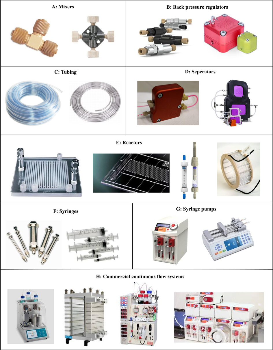
Typical continuous flow components and systems.
The affordability barrier impeding the adoption of continuous flow technology has intrigued researchers to investigate low-cost manufacturing of continuous flow equipment using 3DP technology. The use of 3DP technology has rapidly grown since Kitson et al. (2012) reported on a pioneering ‘reactionware’ concept in which a number of utility FDM 3D printed polypropylene continuous flow reactors were fabricated and used for reductive amination and alkylation reactions, large polyoxometalate synthesis and gold nanoparticle synthesis. Rossi et al. (2018) reviewed some examples of 3DP use in continuous flow synthesis (Avril et al., 2017; Capel et al., 2017, 2013; Dragone et al., 2013; Elias et al., 2015; Hornung et al., 2017; Rao et al., 2017; Rossi et al., 2017, 2015). A minireview by Rossi et al. (2018) highlighted the success of 3DP in flow chemistry at that time and has led to researchers further exploring this avenue in search of cost effective and efficient continuous flow systems. Recent advances in 3DP and flow chemistry convergence are reviewed herein.
Neumaier et al. (2019) printed syringe pumps and various flow reactor cells for the preparation of glycosyl donors, glycosylation and azidation reactions (Figs. 3 and 4). The authors used the FDM 3D printer (Anet A8) for reactor fabrication by taking advantage of the inexpensive and chemically stable polypropylene build material. Reactor R2 with circular channel profile (1.5 mm ID) was fabricated first and had large distances between the reaction channels (Fig. 3A [iii]). Unfortunately, it was not leak proof because of the circular channel profile. Efforts to realise leak proof reactors with elongated reactor paths resulted in the fabrication of an R1 reactor with square channel profiles (1.2 mm × 1.2 mm diameter) thereby making it leak proof (Fig. 3A [i, ii]). Reactor path elongation was achieved by decreasing the distance between the channels affording a reactor total volume of 1.05 mL. R1 reactor has two inlets with a subsequent zigzag mixing structure and one quench inlet. The authors went on to fabricate a bigger leak proof reactor R3 with a total volume of 1.5 mL and a polylactic acid reactor rail which facilitates 1/16 in. tubing (0.75 mm ID) connection to the reactor using standard poly(etheretherketone) (PEEK) High Performance Liquid Chromatography (HPLC) fittings (Fig. 3B). A 12 μL microreactor with 200 μL channel was successfully fabricated (Fig. 3C). Due to polypropylene spreading during extrusion-based 3D printing, a channel size of less than 200 μL was impossible. This 12 μL microreactor (200 μL channel width) is currently the smallest FDM-polypropylene printed reactor in literature. Generally, these reactors have smooth channel structures compared to the other FDM-polypropylene printed reactors (Neumaier et al., 2019; Rossi et al., 2018).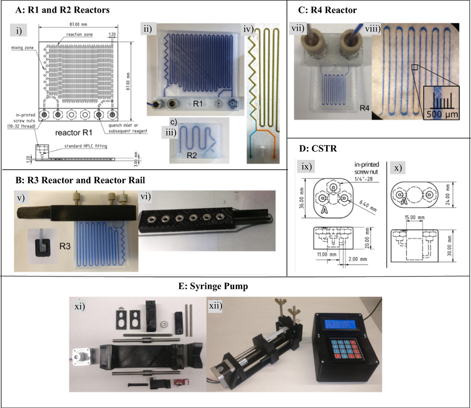
3D printed continuous flow equipment (Neumaier et al., 2019). (A) R1 CAD drawing, R1 reactor and early stage prototype reactor R2. (B) R3 reactor and reactor rail. (C) R4 microreactor. (D) Continuous stirred tank reactor (CSTR). (E) Syringe pump. The images are reproduced with permission from Neumaier et al. (2019).
The continuous flow reactions performed in the 3D printed equipment by Neumaier et al. (2019).
The authors also fabricated two types of continuous stirred tank reactors with two and three inlets, which were used for the premixing and extraction steps (Fig. 3D). Pumps are the key components for continuous flow systems as they are used to drive reagents through flow reactors for reactions to occur. They control how the fast or slow reactants pass through reactors thus determining the reaction/residence time depending on the size of the reactor. Neumaier et al. (2019) printed a rack of four low-cost and simple-to-use syringe pumps controlled by one Arduino Mega 2560 computer (Fig. 3E). Polylactic acid was used for FDM printing of the frame parts of the pump and stepper motors, bearings and all-thread rods, nuts and screws were commercially sourced to finish the assembling of the pumps. The pumps are adaptable to syringes from 1 mL to 50 mL.
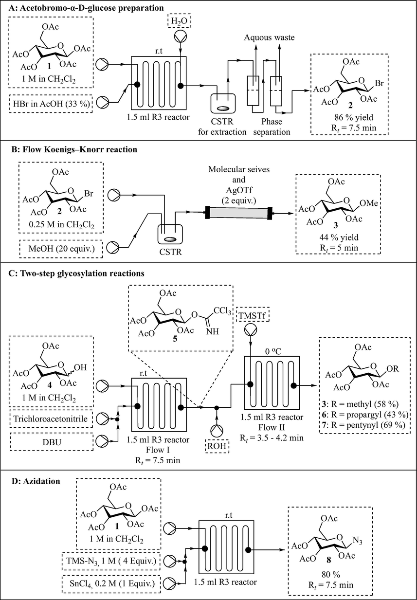
With the 3D printed reactors and pumps in hand, the authors performed glycosylation and azidation reactions as a proof of concept for the continuous flow hardware and reactor set-up (Fig. 4). Pumped using two 3D printed pumps, a solution of pentaacetylglucose 1 in CH2Cl2 (1 M) was treated with HBr in AcOH (33%) in a 1.5 mL polypropylene-printed reactor (R3) at room temperature for 7.5 min residence time. Reaction workup and product isolation was done inline using a 3D printed CSTR and a phase separation system to afford acetobromo glucose 2 in 86% yield (Fig. 4A). It is noteworthy that the polypropylene reactor R3 withstood the acidic conditions and the authors successfully integrated inline workup procedure to come up with a scalable procedure for acetobromo glycoses preparation. The authors went on to perform Koenigs–Knorr glycosylation conditions with silver triflate as activator using the 3D printed pumps and CSTR (Fig. 4B). A solution of acetobromo glucose 2 in DCM (0.25 M) and MeOH were pumped into a printed CSTR and the mixture was subsequently treated with AgOTf in a column reactor to afford methyl glycoside 3 in 44% yield and 5 min residence time.
Neumaier et al. (2019) demonstrated a two-step glycosylation process using two 3D printed reactors connected in series and reagents were pumped using the printed pumps (Fig. 4C). In the first step, glucose 4 was treated with trichloroacetonitrile in the presence of DBU at room temperature for 7.5 min in the first R3 reactor affording glycosyl donor 5 in situ. Glycosyl donor 5 was subsequently treated with various alcohols in the second R3 reactor at 0 °C and 3.5–4.2 min residence times to afford respective glycosides 3, 6 and 7 in 58%, 43% and 69% yield, respectively. Lastly, the authors demonstrated efficient and safe preparation of potentially explosive azide 8 in which pentaacetyl glucose 1 was treated with trimethylsilyl azide in the presence of SnCl4 for 7 min in a printed reactor R3 to afford azide 8 in 80% yield (Fig. 4D). Remarkably, the authors successfully demonstrated the manufacturing of a variety of low-cost continuous flow equipment (reactors, CSTR and pumps) for less than €300. Several reactions were successfully performed using this equipment in which the handling of harsh acidic conditions, potentially explosive azide chemistry, multistep synthesis and inline work-up was demonstrated.
Scotti et al. (2019) developed a simple continuous flow chemistry microreactor with an electrospray ionization (ESI) tip for real time mass spectrometric reaction monitoring (Fig. 5A and B). The 3D microreactor was printed with powder bed fusion technology in which 316L stainless steel powder (20–50 μm particle size) was melted with a 200 W continuous wave laser operating at 1070 nm wavelength. The post printing processes included blowing of the unmelted powder out of the channels and manual polishing of the reactor tip. Excluding the ESI sharpening process, the estimated total cost of the printed reactor is €20. Microreactor functionality was tested by analyzing an inverse electron-demand Diels-Alder and retro Diels-Alder cascade of reactions (Fig. 5C). Trans-cyclooctene-amine hydrochloride 9 (0.13 mM) and 3-[4-(6-methyl-1,2,4,5-tetrazin-3-yl)phenoxy]propan-1-amine hydrochloride 10 (0.25 mM) were reacted in the microreactor fitted with inline ESI-MS reaction monitoring to afford 4,5-dihydropyridazine 12 via cycloadduct 11. Although the microreactor was found not perfectly suited for studying reaction kinetics and mechanisms due to channel surface roughness induced memory effects, it is useful for other applications such as a low cost disposable microreactor (Scotti et al., 2019). Furthermore, the good chemical, thermal and mechanical stability of the build material (stainless steel 316L) makes it a useful device in continuous flow chemistry.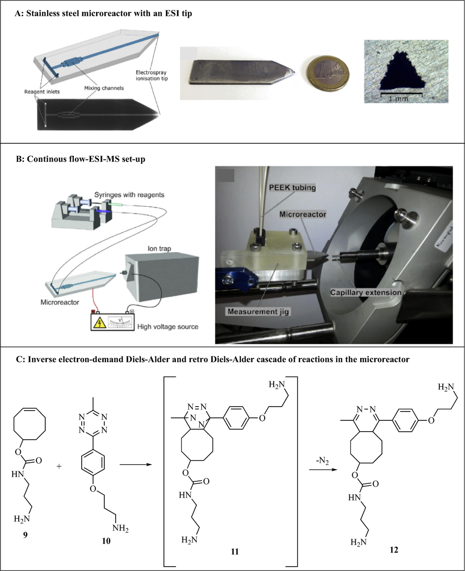
Continuous flow-ESI-MS system with a 3D printed stainless microreactor and a cascade of reactions performed using the reactor. The images are reproduced with permission from Scotti et al. (2019).
Although various individual 3D printed continuous flow components such as microreactors and pumps have been reported, not much has been done towards 3DP of full continuous flow systems. To this effect, Penny et al. (2019) developed a low-cost, small-footprint and modular full 3D printed continuous flow system (Fig. 6). Reagents flow in the system was compressed air driven using Duran pressure bottles pressurised to 1.5 bar and system used commercial stirrer hot plate as heating source. The authors designed circular disk reactors (75 mm diameter, 7 mm high with 2 mm ID reactor channel) that fits DrySyn Multi-E base using Tinkercad free online CAD software (Autodesk). The 3D circular reactors (4.2 mL internal volume) were printed with polypropylene with the aid of an Ultimaker 3 3D printer. To complete the continuous flow system, the other components were also 3D printed using an Ultimaker 3 3D printer (Fig. 6).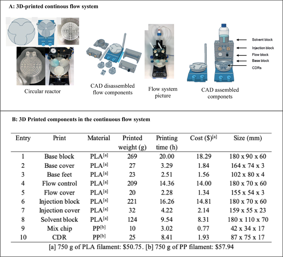
3D printed full continuous flow system. The images are reproduced with permission from Penny et al. (2019).
The continuous flow system was printed at a total cost less than $70 excluding the cost of the commercial stirrer hot plate. This is significantly less than the cost of a commercial continuous flow system which typically costs an excess of USD $20,000 (Penny et al., 2019). Capillary resistors concept was used to achieve consistent flow rates of the air driven reagents as well as act as back pressure regulators, thus enabling the reaction to be carried out at near or above solvent boiling point. The functionality of continuous flow system was tested using SNAr reactions between 5-nitro-2-chloropyridine 13 with a variety of phenols (Fig. 7). The authors impressively designed, developed and 3D printed a simple low-cost continuous flow system which avoided the use of expensive pumps or syringe pumps and regular backpressure regulators. Furthermore, its functionality was successfully demonstrated using SNAr reactions. Without doubt, this affordable printed system will enable the exploitation of this powerful emerging technology (flow chemistry) by ‘low-budget’ chemistry laboratories.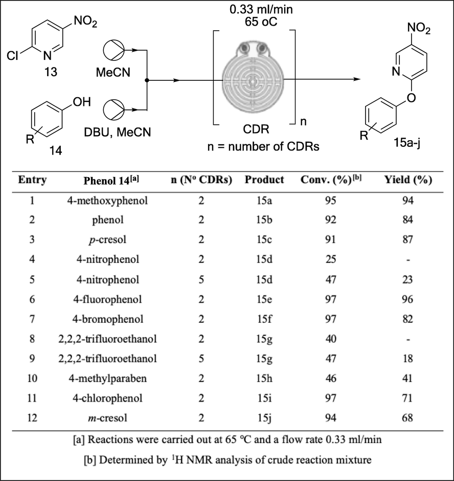
SNAr reactions between 5-nitro-2-chloropyridine 14 and a variety alcohols explored in the 3D printed continuous flow system (Penny et al., 2019).
One key advantage of continuous flow chemistry is the ability to perform reactions at 100–150 °C above their normal boiling point (superheating), by pressuring the system. As a result, 1000 times faster reaction rates are achieved. Furthermore, pressure control is important for maintaining consistent flow rates in the continuous flow system especially for reactions involving gases. Continuous flow systems are usually pressured using back pressure regulators (BPRs). Therefore, BPRs are essential components of a continuous flow system. Although there are many commercially available BPRs, most are out of reach of many low budget laboratories. For example, Zaiput BPR cost more that USD $1000. Walmsley and Sellier (2020) designed, developed and 3D printed a low cost BPR using an Ultimaker3 printer (Fig. 8). Computation design of the BPR was performed using open-source software, Tinkercad® and Ultimaker Cura. The BPR were designed and printed in two parts, where two polypropylene face plates (gas and liquid face plate) sandwiches a (polytetrafluoroethylene) PTFE membrane diaphragm. Although polypropylene has moderate resistance to common solvents, the authors designed the BPR in a way that ensures minimal contact of solvents with the polypropylene face plates. The sandwiched 0.1 mm thick PTFE membrane provides a protective layer as well as enabling gas-liquid separation in the assembled BPR. M4 stainless steel wing nuts were used to hold the two-phase plates together. PTFE gasket, silicone O-rings and the straight pneumatic push fit 4 mm OD male M5 adapter were also necessary to complete the BPR assembly (Fig. 8). The BPR was successfully tested for leaks and functionality using tetrahydrofuran (THF) and acetonitrile (ACN) using flow rates up to 3 mL/min and gas pressure of up to 2 bar.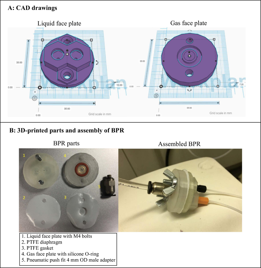
3D printed BPR designed and developed by Walmsley and Sellier (2020).
Alimi et al. (2019) developed a continuous flow system consisting of a syringe pump, Pd/Co3O4 packed column reactor and a mixer using 3DP technology (Fig. 9). The continuous flow components were designed with an open-source OpenSCAD software and printed by FDM 3D printer using a thermoplastic filament, polylactic acid. The column reactor (20.0 mm long, 4.00 mm outer diameter and variable radii (r1 = 0.97 mm and r2 = 2.2 mm)) was 3D printed and packed with Pd/Co3O4. The printed pump consisted of parts, the fixed body and the plunger. The pump is controlled by Arduino Mega computer and can accommodate a wide range of commercially available syringes (1–20 mL). A mixer with two reagent inlets and one outlet (0.97 mm channel radius) was also 3D printed. The functionality and integrity of the 3D printed assembled continuous flow system was tested using the reduction of 4-nitrophenol 16 to afford 4-aminophenol 17 in 98% conversion with 8 min residence time (Fig. 9C).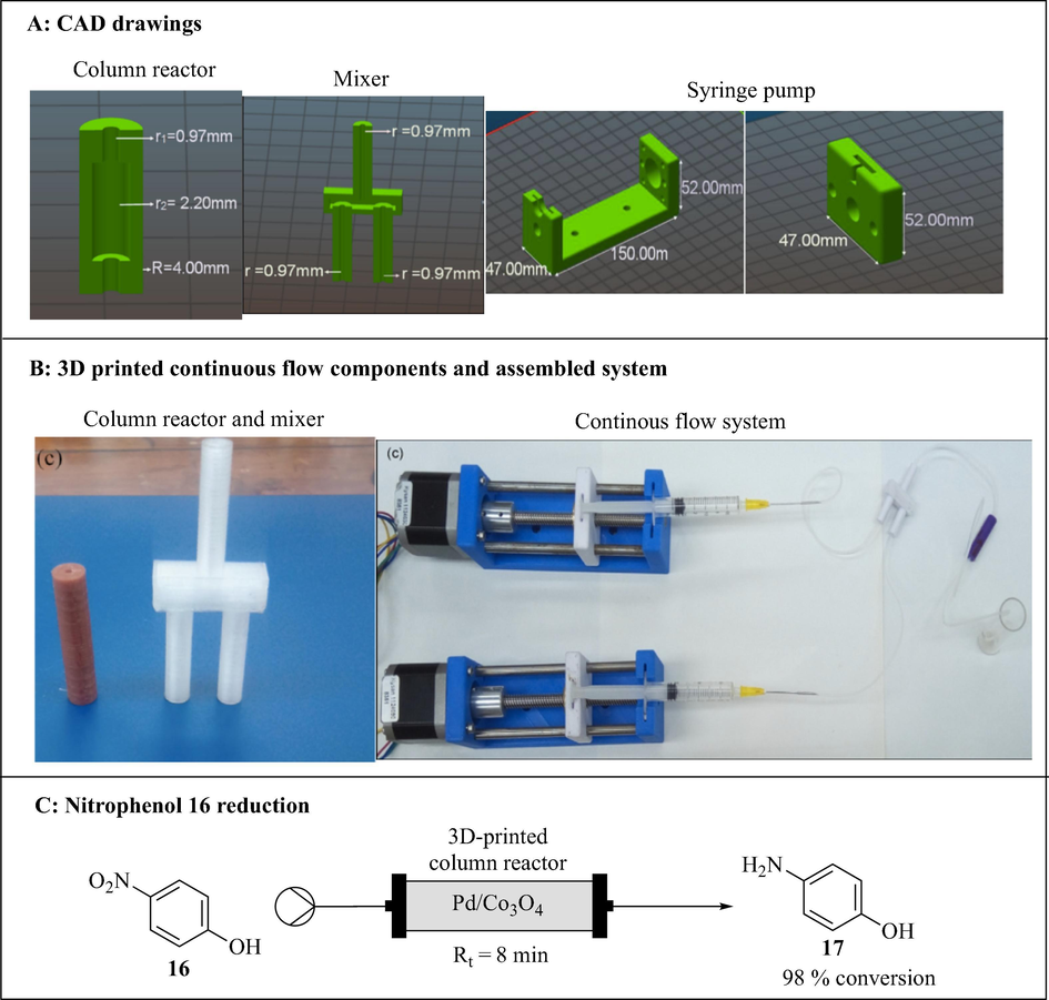
3D printed continuous flow system. The images are reproduced with permission from Alimi et al. (2019).
After the initial success of the 3D printed column reactor packed with Pd/Co3O4 catalyst (Alimi et al., 2019), Alimi et al. (2020) went on to print another column reactor which was packed with immobilised palladium nanocatalyst (Pd/Co3O4) for morin 18 oxidation (Fig. 10). The 3D printed column reactor was designed with OpenSCAD software and printed by an FDM printer (Prusa i3 MK3S) using polylactic acid filament. Morin 18 oxidation was successfully performed in the 3D printed column reactor to afford morin oxide 19 in 98% conversion with 8 min residence time (Fig. 10).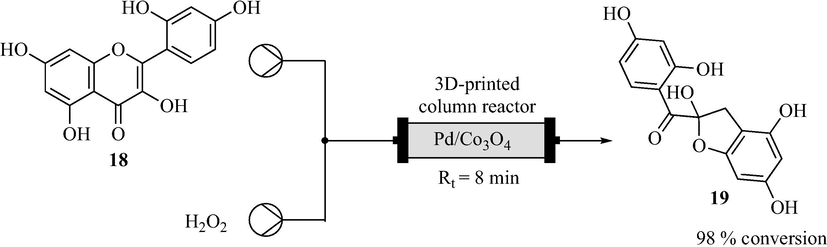
3D printed continuous flow column reactor and morin 18 oxidation (Alimi et al., 2020).
With the experience accumulated in their previous applications of 3DP technology for heterogenous catalysis in continuous flow (Alimi et al., 2020, 2019), Alimi et al. (2020) developed a continuous flow system consisting of polylactic acid-based syringe pumps, palladium immobilized alumina monolith and a polypropylene-based column reactor (Fig. 11). Deposition-precipitation method was used to immobilise palladium nanoparticles on the alumina monolith which was fabricated from a 3D printed template. All the 3D printed parts were designed using OpenSCAD software and printed by FDM printer (Prusa i3 MK3S). The performance of the 3D printed continuous flow system was investigated using the epoxidation of styrene 20 with tert-butyl hydroperoxide (TBHP) resulting in 60% conversion of the styrene 20 and 79% selectivity of epoxide 21 (Fig. 11).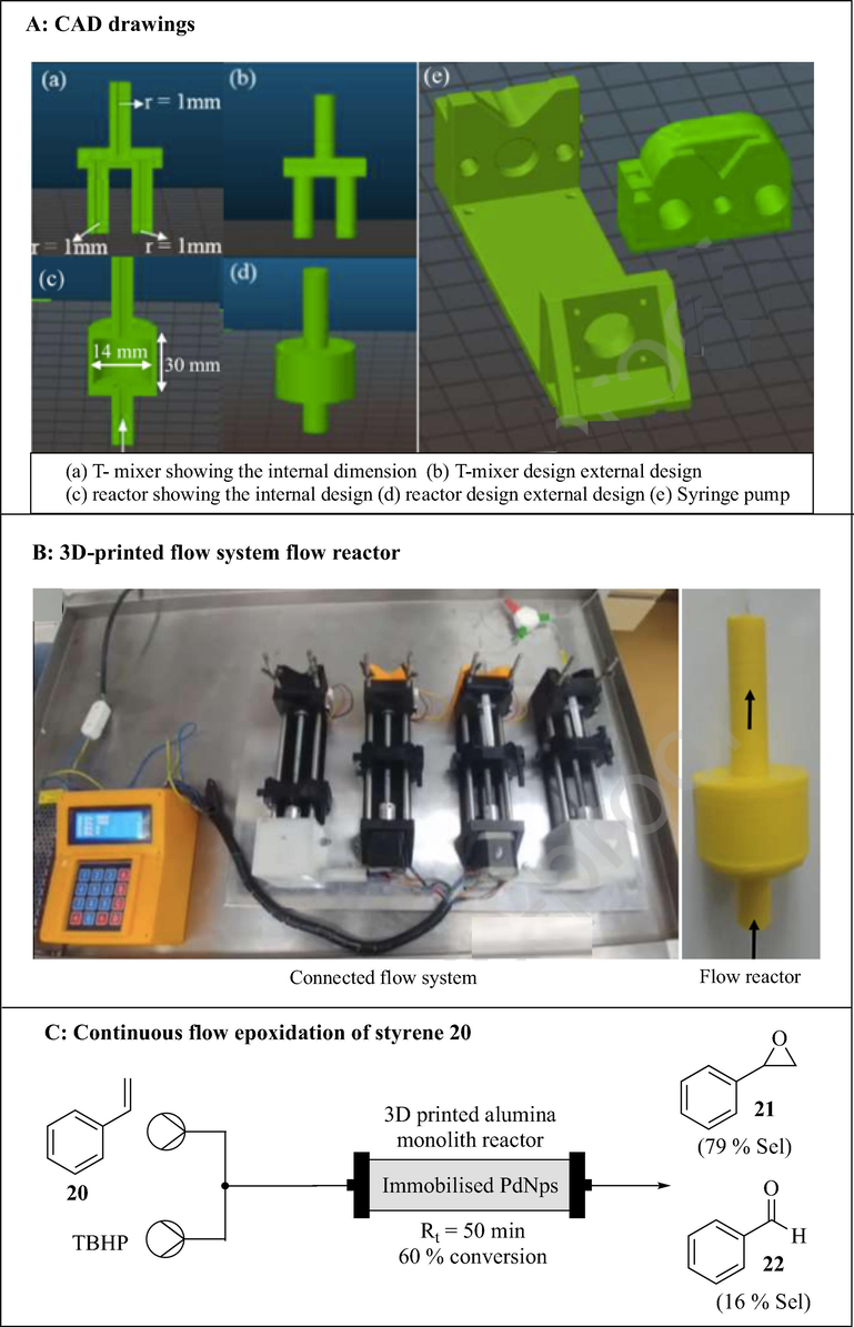
3D printed continuous flow system consisting of syringe pumps, Pd immobilized alumina monolith and a polypropylene-based flow reactor. The images are reproduced with permission from Alimi et al. (2020).
Although PEEK has superior chemical and thermal stability, it is a difficult thermoplastic polymer to print due to a high melting point and viscosity (Arif et al., 2018; Vaezi and Yang, 2015; Valentan et al., 2013). PEEK requires high printing temperatures (370–430 °C) (Vaezi and Yang, 2015) which can result in warping and delamination of layers due to thermal stresses (Harding et al., 2020). However, this can be avoided by printing PEEK in a heated chamber with temperatures higher than 150 °C build plate (Cai et al., 2015; Vaezi and Yang, 2015; Yang et al., 2017). Harding et al. (2020) fabricated a low cost, chemical resistant and strong continuous flow reactors with integrated mixing elements from PEEK using a FDM 3D printer (Funmat HT) (Fig. 12). The parts for the flow reactors were designed in Autodesk Fusion 360. Due to the superior mechanical and thermal properties of PEEK, the reactor withstood elevated temperatures and high pressures of at least 30 bar leading to superheating of solvents in the reactions. The performance of PEEK in printing flow chemistry reactors was investigated using a SNAr reaction of 2,4-difluoronitrobenzene 23 with morpholine 24 with telescoped liquid–liquid extraction (Fig. 12). The continuous flow system was efficient with 97% conversion of the starting material being achieved. 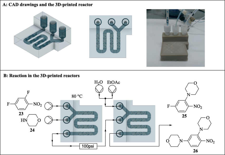
3D printed continuous flow reactor. The images are reproduced with permission from Harding et al. (2020).
One of the primary advantages of continuous flow chemistry over the conventional batch process is the ability to safely handle highly reactive and exothermic reactions thus enabling novel chemical processing windows to be created. Due to the inherent safety of continuous flow system as a result of features such as lower reaction volumes, high surface-to-volume ratios and rapid heat dissipation (Sagandira and Watts, 2020, 2019; Scotti et al., 2019; Trojanowicz, 2020), thermodynamic, fluid dynamic, and kinetic investigations are rarely done at small scale (Maier et al., 2020a,b). However, these investigations are important for safe and efficient industrial application (Maier et al., 2020a,b). Reaction calorimetry provides important safety data such as enthalpy of reaction, activation energy, heat capacity of a reaction mixture and reaction rate (Maier et al., 2020a,b). Reaction enthalpy is a key aspect in reactor design and safety evaluation. Maier et al. (2020a,b) reported a modular 3D printed calorimeter for reaction calorimetry in continuous flow (Fig. 13). The calorimeter can withstand harsh reaction conditions. Selective laser melting (SLM) and digital light processing (DLP) 3DP techniques were used in the calorimeter fabrication. Due to high chemical, mechanical stability and excellent heat transfer rates of stainless steel, the reactor plate and cooling blocks were printed by SLM of stainless steel. This enabled the usage of highly reactive compounds and organic solvents at elevated pressures. The calorimeter casing was fabricated by DLP of a cheap UV-curable resin, which provided good thermal insulation and necessary strength to support a whole calorimeter. The calorimeter’s functionality was validated with a series of experiments which produced a well-known heat flux.
Exploded view of the designed calorimeter with the 3D printed modular segments. Reproduced with permission from Maier et al., 2020a,b.
Most recently, Maier et al. (2020a,b) demonstrated the high potential of 3DP technology for cost- and time-efficient production of custom-made continuous flow reactors, applicable for the synthesis of APIs (Figs. 14–16). Two different 3DP techniques (SLM and DLP) were used depending on reaction requirements. Harsh chemical reactions were performed in stainless steel reactors 3D printed via the SLM technique while a UV-curable resin, processed via DLP, was used as build material for reactors used for milder reactions (Maier et al., 2020a,b). The authors reported three examples of 3D printed reactors and their application in API synthesis. The first example involved aerobic oxidation of a Grignard reagent 27 by molecular oxygen to corresponding phenol 28 in various stainless-steel reactors namely APO3, APO4, split-and-recombine reactor (SaRR) and CSTR cascade (Fig. 14). In the AP03 reactor, chaotic mixing is induced by channels which are arranged according to a helicoidal structure with alternating change of the direction of curvature. The mixing principle of the APO4 reactor is based on splitting the flow into smaller lamellae, consequently increasing the area of contact between the incoming streams. The CSTR-cascade has 10 vessels with a 3 mm internal diameter (ID), each equipped with a micro stirrer to enhance mixing. These vessels are connected via a 0.6 mm ID channel. The desired product 28 was afforded in 42% and 28% yield for AP03 and AP04 reactors, respectively. The improved yield observed with the AP03 reactor compared to the AP04 reactor was due to better mixing. The AP03 performed slightly better than the SaRR. Best results (53% yield) were achieved with a CSTR cascade reactor due to more efficient mixing. Apart from the channel structure design, channel ID was also found to influence yield. As expected, smaller channel diameters were accompanied by improved yields because of better mixing induced by shorter diffusion distances.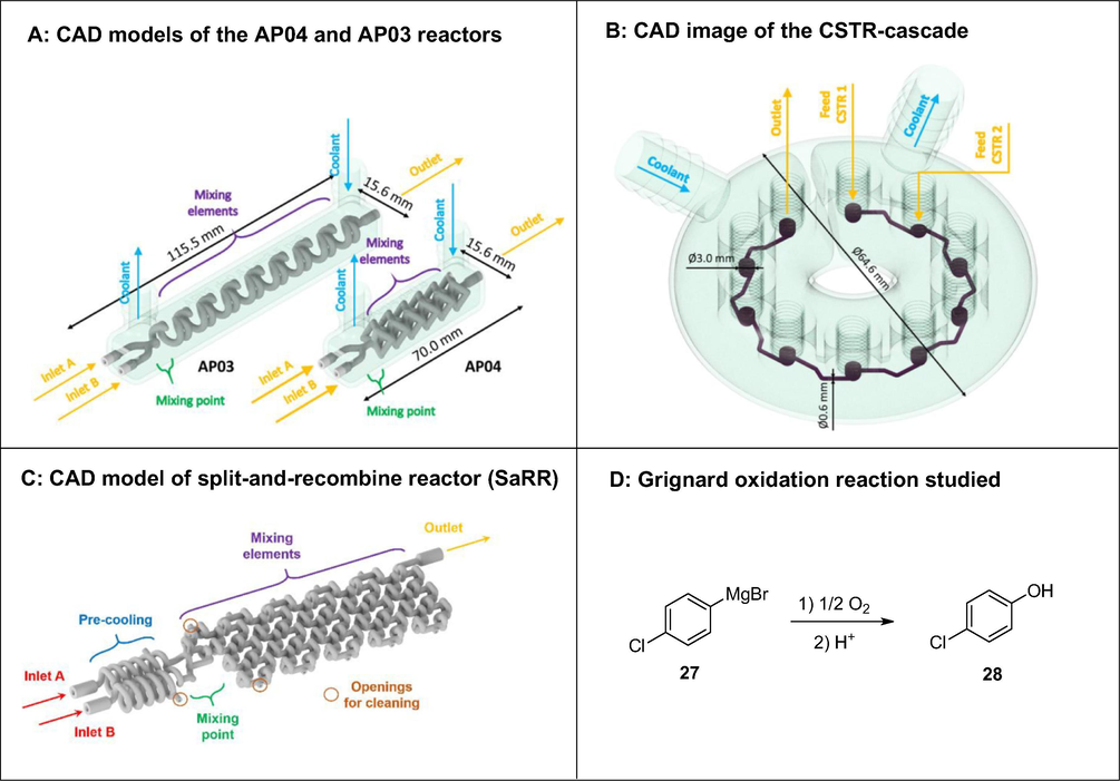
Grignard oxidation using molecular oxygen investigated in various 3D printed continuous flow reactors (APO3, APO4, SaRR and CSTR cascade). Reproduced with permission from Maier et al., 2020a,b.
3D printed SaRR incorporated in the multistep continuous flow synthesis of a valsartan precursor 32.
3D printed CSTR incorporated in the two-step continuous flow synthesis of 4-hydroxystilbene 35. Reproduced with permission from Maier et al., 2020a,b.
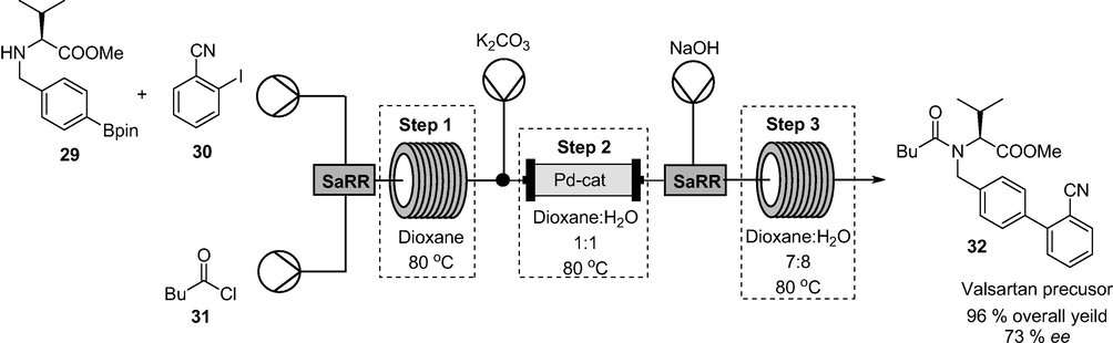
Valsartan is a non-peptide angiotensin II receptor blocker for the treatment of hypertension. In another example, the authors used SaRR in Fig. 14 to achieve efficient mixing in the multistep synthesis valsartan precursor 32 (Fig. 15). Valsartan precursor 32 was afforded in 96% overall yield and 73% enantiomeric excess in 60 min total residence time (Maier et al., 2020a,b).
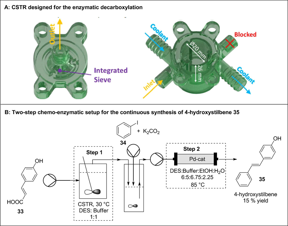
In the last case, the authors used a CSTR made of a UV-curable resin in the first step of a multiphase enzymatic decarboxylation followed by a Heck cross-coupling reaction to afford resveratrol derivatives (Fig. 16). The enzymatic decarboxylation of para-coumaric acid 33 by phenolic acid decarboxylase was performed in a 3D printed CSTR before undergoing a Heck cross-coupling reaction with 34 to afford 4-hydroxystilbene 35 in 15% overall yield with a space–time yield of 703 mg/(l·h) (Maier et al., 2020a,b). Interestingly, this translates to a 35% space time yield improvement compared to their previous work in which a CSTR was not used. Despite the low overall yield, the first step performed in the CSTR was accompanied by an excellent selectivity (>99%) and 70% conversion. Ultimately, reaction engineering and 3DP of continuous flow reactors was successfully combined to enable efficient synthesis of API precursors in continuous flow.
3 Quality considerations for 3D printed flow reactors
Pharmaceutical manufacturing is subject to regulatory constraints, more so where converging technologies are involved. To help with standardization of the 3DP process, Abdollahi and co-workers designed an expert-guided optimization (EGO) strategy to minimize the trial and error approach of optimizing 3DP critical process parameters (Abdollahi et al., 2018). The reported EGO strategy is applicable to FDM, SLA and powder-based printing techniques and it makes use of an algorithmic search together with expert intervention to provide insight into the effect of factors that are important in structural integrity of print parts. Ultimately, selection of the appropriate 3D printer and material (ink) is determined by key factors such as the maintenance of geometrical integrity, repeatability, and surface quality of resulting prints (Mou and Koc, 2019). Quality assessments of 3D printed flow reactors must be performed from the early stages of process development to satisfy regulatory requirements.
3.1 3D printing technique and build material
Although there are numerous 3DP techniques, each technique has its own engineering and material limitations that must be religiously considered before its application in the manufacture of continuous flow components (Capel et al., 2013; Dragone et al., 2013; Penny et al., 2019; Rossi et al., 2018). Due to their inherent characteristics, not all 3DP techniques have been used to manufacture flow chemistry components (Harding et al., 2020; Kitson et al., 2016; Neumaier et al., 2019; Rao et al., 2017; Waheed et al., 2016). Among these, MJP, SLS, LOM, SLA and FDM are the commonly used techniques (Capel et al., 2013; Dragone et al., 2013; Neumaier et al., 2019; Rao et al., 2017; Rossi et al., 2018; Waheed et al., 2016). An example of engineering imposed limitation is in powder-based techniques such as SLS and powder-based ink-jetting where it is extremely difficult to fabricate microchannels as a result of the excess and unsolidified powder material that is impossible to remove (Kitson et al., 2016; Neumaier et al., 2019). Polymers are commonly used as build materials (inks) for efficient and inexpensive fabrication of continuous flow components and systems (Capel et al., 2013; Dragone et al., 2013; Harding et al., 2020; Rossi et al., 2018; Scotti et al., 2019). However, some polymers are characterised by chemical inertness and thermal stability concerns. An example of a build material imposed limitation is in SLA and some inkjet printing processes where epoxy- or acrylate- based photopolymers are unstable in standard commonly used organic solvent and extreme pH (Kitson et al., 2016). Due to affordability and rapid prototyping, poly(dimethylsiloxane) (PDMS) is a specific example of a very common ink in 3DP which does not have a wide range of application in organic reactions as it can absorb the reactants and swells in most nonaqueous solvents (Dragone et al., 2013; Rossi et al., 2017). Conversely, polypropylene (PP) is a thermo-polymer ink that is inert in a range of organic reagents and solvents and is cheaper than PDMS (Dragone et al., 2013). Continuous flow components with a wide range of chemical inertness and thermal stability are usually made of materials such as silicon and glass (Capel et al., 2013; Dragone et al., 2013; Rossi et al., 2018). Aforementioned, they are usually made by conventional specialised and expensive techniques such as micro-machining and chemical etching (Capel et al., 2013). Not all 3DP processes are capable of producing components with acceptable mechanical and build resolution using the desired inks (Dragone et al., 2013; Scotti et al., 2019). In addition, materials behave differently in the various printing conditions and will not always conform to the CAD model (Siyawamwaya et al., 2019). Therefore, these are fundamental challenges of the application of this technology in chemistry however, it is noteworthy that the range of printing inks in continuous flow chemistry is growing with the use of metals and metallic alloys being reported (Capel et al., 2013; Kitson et al., 2016; Scotti et al., 2019).
3.2 3D printing design approach
3DP ink consists of material compatible with the respective printer and it has an impact on the printing parameters used. Parameters such as nozzle size, surrounding temperature, scanning speed and dispensing pressure influence the physico-mechanical properties of the 3D printed constructs. Print quality is often determined by an interplay of crucial factors such as the distance between the needle tip and print bed, type and diameter of the nozzle, printing pressure and speed (Hadley and Ward, 1975). The printing process may lead to alterations in the ink material thereby leading to deviations in the CAD geometry of the constructs (Alharbi et al., 2016). Depending on the viscosity of the material, it may be necessary to use a wider nozzle and/or lower pressure and this ultimately limits print accuracy and resolution, properties which are directly proportional to the thickness of the strands produced by the printer (Giuseppe et al., 2018; Siyawamwaya et al., 2016).
The 3DP direction shapes the mechanical response of the printed part. With the horizontal orientation (Fig. 17), the first layer that is in contact with the build platform usually has a different surface structure compared to the uppermost layer (Chen et al., 2017; Gonzalez Ausejo et al., 2018; Rydz et al., 2019). Polymer molecules inherently orient themselves in the direction of the ink flow thereby resulting in anisotropic mechanical properties. The material’s orientation-induced mechanical properties are caused by weak interlayer bonding or porosity during ink deposition and the extent of anisotropy depends on the build direction during the printing process (Es-Said et al., 2000; Guessasma et al., 2015; Hadley and Ward, 1975; Sood et al., 2012).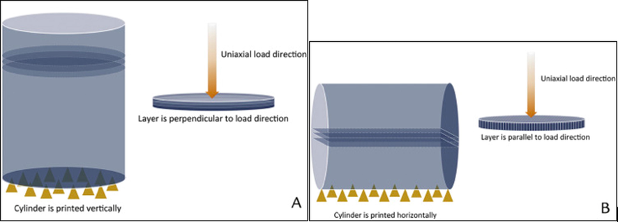
(A) Illustration of printing direction and layer orientation relative to load direction of a vertically printed cylinder, layer oriented perpendicular to load direction. (B) Illustration of printing direction and layer orientation relative to load direction of a horizontally printed cylinder, layer oriented parallel to load direction. Yellow triangles represent the printing support base. Reproduced with permission from Es-Said et al. (2000).
3.3 Geometrical integrity
One of the challenges with 3DP is the maintenance of geometrical integrity post printing. The structural geometry of the printed construct is fundamental where the intricate details in the CAD design serve a functional rather than aesthetic role. According to a study carried out by Giuseppe et al. (2018) when a 27-gauge (0.23 mm internal diameter) hollow needle was used for printing, the thinnest printed strand width was 0.32 mm. The strand width was wider than the internal needle diameter due to gravity pooling effects on the ink. Fig. 18 depicts how the strand widths are similar but not identical within the construct, therefore demonstrating a common problem with 3DP.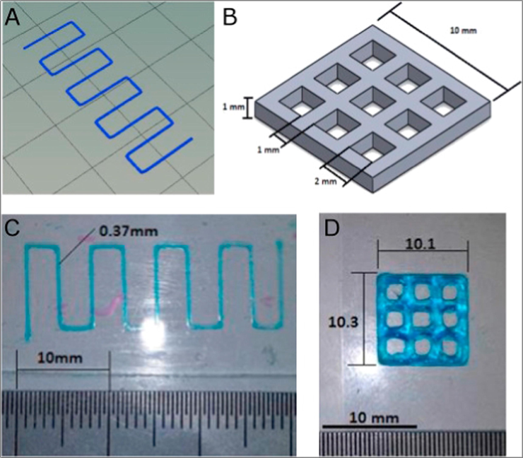
(A) Strand thickness test design, (B) print accuracy multilayer grid design, (C) printed strand with width analysed using ImageJ and (D) printed grid with dimensions determined using ImageJ. Reproduced with permission from Giuseppe et al. (2018).
Material-specific spatial deviations have also been observed. Abdollahi et al. (2018) reported on how printing complex objects with polylactic acid resulted in objects that conformed to the CAD design whereas the epoxy and PDMS prints exhibited 2–3 times more deviations to the same original design. In addition, drying processes, if applicable, may result in alterations of the print structures. Wang et al. (2020) made comparisons of different cellulose nanofibrils: unmodified (CNF), acetylated (AcCNF) and TEMPO-oxidised (TOCNF). Findings from the study showed that TOCNF and AcCNF prints maintained their structural form after 3DP with improved results obtained after freeze-drying of the objects compared to drying at room temperature. From the images shown in Fig. 19, the surface finish and rectangular spaces within the prints were inconsistent.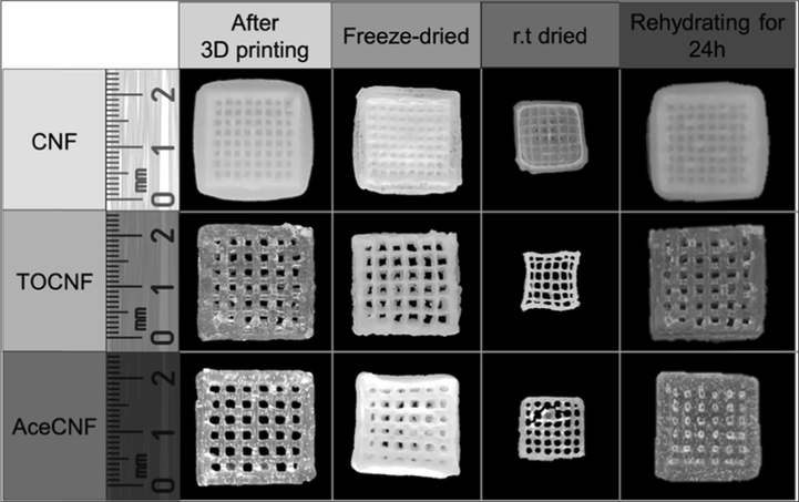
Images of CNF, TOCNF, and AcCNF scaffolds in the wet state soon after printing; at 24 h after freeze-drying and room temperature drying; and after 24 h of rehydration by immersion in water of the freeze-dried samples. Reproduced with permission from Wang et al. (2020).
3.4 Surface morphology
High surface roughness is another challenge exhibited by 3D printed objects (Siyawamwaya et al., 2019). Surface morphology may be assessed with the aid of scanning electron microscopy (SEM). The layer-by-layer approach of 3DP potentially leads to accumulation of compressive stresses within printed constructs. As more layers are added, previous layers are restricted from shrinking or solvent evaporation thereby resulting in layer cracking (Gonzalez Ausejo et al., 2018). A minimal number of layers and thinner strands are expected to prevent the collapse of the printed part. However, small strand widths could potentially lead to 3D object deformation and mechanical failure because of the subsequent need to increase the number of layers. Minimizing or eliminating gaps between layers enhances mechanical strength but conversely causes overlapping of layers thus leading to the formation of irregular surface morphologies (Gonzalez Ausejo et al., 2018). Cumulative deformations within a printed construct (Fig. 20a) are precursors for consequential de-bonding (Fig. 20b) that weakens the strength between print layers.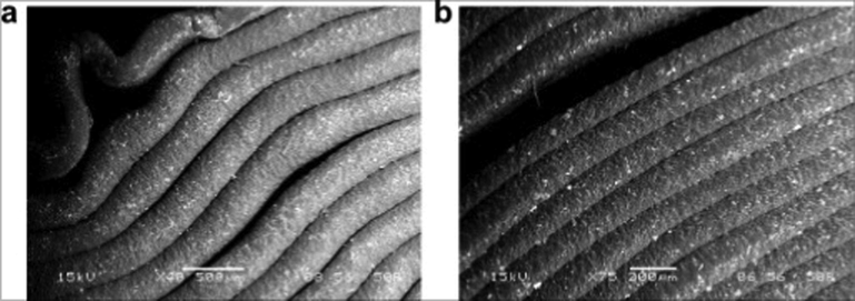
Microphotographs of specimens after compressive failure: (a) failure due to buckling and (b) de-bonding between fibers (the surfaces of the test part were examined by scanning electron microscope (SEM) JEOL JSM-6480LV in the LV mode). Reproduced with permission from Gonzalez Ausejo et al. (2018).
Mou and Koc, (2019) compared surface morphologies from constructs printed by FDM, SLA and MJP. FDM technology resulted in objects with rough surfaces, SLA produced constructs with smoother surfaces while those produced by MJP had comparable surface roughness with confirmed roughness at the microscopic level. These findings inferred that post-printing processing will be required to make the printed constructs usable. Microstructural deviations may occur during 3DP thereby leading to defects in the internal structure of the printed part. The laser power in SLS and heat in FDM potentially increase surface roughness and may cause development of microcracks on printed constructs. Non-destructive industrial X-ray micro-computed tomography (µCT) can be performed to analyse the fidelity of the internal structure of constructs (Harding et al., 2020). The µCT scan reveals structural defects such as voids, porosity or cracking on the surface of the flow reactors. For example, Fig. 21 shows defects detected by a µCT scan of a Ti-6Al-4V coupon produced by selective laser melting (du Plessis et al., 2018). The pore formation resulted from weaknesses created in the coupon in the build direction during 3DP process.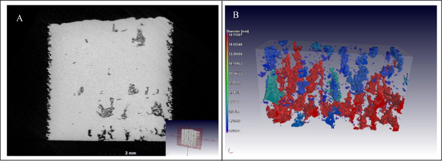
Images of tree-like voids grown in the build direction, with unconsolidated powder trapped inside the closed voids: (a) slice view and (b) 3D rendering. Reproduced with permission from du Plessis et al. (2018).
4 Conclusion and future outlook
Developing countries can harness the use of 3DP technology to fabricate affordable continuous flow technology equipment that enables capacity building for local manufacturing of APIs. For a successful 3D manufacture and application in flow chemistry, it is therefore important to first consider the intended use of the 3D printed component and then determine the best 3D printing technique with all engineering and build material limitations factored in. Furthermore, the technique and reactor designs are universally accessible, thanks to the thriving open source community. 3D printing in continuous flow chemistry is poised to change pharmaceutical manufacturing by allowing the setup of a cost-effective cutting-edge manufacturing technology, making it highly attractive for implementation in developing settings. The maintenance of acceptable regulatory standards at all stages of the production pipeline is a crucial component of good manufacturing practices. From the reviewed papers, 3DP reactionware is a promising field however, there remains a gap in research on quality attributes of these printed equipment. There still remains a need for clearly defined frameworks of regulatory approval of the 3D printed flow equipment. Factors that influence the production of good quality 3D printed continuous flow reactor equipment include 1) 3D printing technique and choice of material, 2) design approach, 3) geometrical integrity of the printed parts and 4) quality of the surface of the printed objects. Collaborative efforts of key disciplines will be the ‘glue’ that will enable operationally achievable results from merging 3DP and continuous flow chemistry technologies. Despite some limitations associated with the use of 3DP technology in flow chemistry, this technological convergence poses as the new chemical industrial revolution where chemicals and APIs can both be produced efficiently, cost effectively and most importantly with exceptional design freedom. A careful implementation process will see developing countries harnessing the power of advanced pharmaceutical manufacturing methods to solve their public health needs.
Declaration of Competing Interest
The authors declare that they have no known competing financial interests or personal relationships that could have appeared to influence the work reported in this paper.
References
- Expert-guided optimization for 3D printing of soft and liquid materials. PLoS One. 2018;13:1-19.
- [CrossRef] [Google Scholar]
- Continuous-flow protocol for the synthesis of enantiomerically pure intermediates of anti epilepsy and anti tuberculosis active pharmaceutical ingredients. Org. Biomol. Chem.. 2019;17:1552-1557.
- [CrossRef] [Google Scholar]
- The role of 3D printing in medical applications: a state of the art. J. Healthc. Eng.. 2019;2019
- [CrossRef] [Google Scholar]
- Continuous flow chemistry: where are we now? Recent applications, challenges and limitations. Chem. Commun.. 2018;54:13894-13928.
- [CrossRef] [Google Scholar]
- Effects of build direction on the mechanical properties of 3D-printed complete coverage interim dental restorations. J. Prosthet. Dent.. 2016;115:760-767.
- [CrossRef] [Google Scholar]
- 3-D printed microreactor for continuous flow oxidation of a flavonoid. J. Flow Chem. 2020
- [CrossRef] [Google Scholar]
- Homemade 3-D printed flow reactors for heterogeneous catalysis. Chem. Eng. Res. Des.. 2019;150:116-129.
- [CrossRef] [Google Scholar]
- Performance of biocompatible PEEK processed by fused deposition additive manufacturing. Mater. Des.. 2018;146:249-259.
- [CrossRef] [Google Scholar]
- Continuous flow hydrogenations using novel catalytic static mixers inside a tubular reactor. React. Chem. Eng.. 2017;2:180-188.
- [CrossRef] [Google Scholar]
- Awad, R.H., Habash, S.A., Hansen, C.J., 2018. 3D printing methods, 3D Printing Applications in Cardiovascular Medicine. Elsevier Inc. https://doi.org/10.1016/B978-0-12-803917-5.00002-X
- Why we need continuous pharmaceutical manufacturing and how to make it happen. J. Pharm. Sci.. 2019;108:3521-3523.
- [CrossRef] [Google Scholar]
- Baumann, M., Moody, T.S., Smyth, M., Wharry, S., 2020. A perspective on continuous flow chemistry in the pharmaceutical industry. Org. Process Res. Dev. https://doi.org/10.1021/acs.oprd.9b00524.
- Emerging trends in flow chemistry and applications to the pharmaceutical industry. J. Med. Chem.. 2019;62:6422-6468.
- [CrossRef] [Google Scholar]
- Multi-step continuous-flow synthesis. Chem. Soc. Rev.. 2017;46:1250-1271.
- [CrossRef] [Google Scholar]
- Recent innovations in material research. Mater. Res. Innov.. 2015;19:S51-S55.
- [CrossRef] [Google Scholar]
- Coronavirus disease 2019 in the perioperative period of lung resection: a brief report from a single thoracic surgery department in Wuhan, People’s Republic of China. J. Thorac. Oncol.. 2020;15:1065-1072.
- [CrossRef] [Google Scholar]
- Design and additive manufacture for flow chemistry. Lab Chip. 2013;13:4583-4590.
- [CrossRef] [Google Scholar]
- 3D printed fluidics with embedded analytic functionality for automated reaction optimisation. Beilstein J. Org. Chem.. 2017;13:111-119.
- [CrossRef] [Google Scholar]
- Process intensified flow synthesis of 1H–4-substituted imidazoles: toward the continuous production of Daclatasvir. ACS Sustain. Chem. Eng.. 2015;3:3445-3453.
- [CrossRef] [Google Scholar]
- Synthesis of a Key Intermediate towards the Preparation of Efavirenz Using n-Butyllithium. J. Flow Chem.. 2017;7:37-40.
- [CrossRef] [Google Scholar]
- 3D printing biocompatible polyurethane/poly(lactic acid)/graphene oxide nanocomposites: Anisotropic properties. ACS Appl. Mater. Interfaces. 2017;9:4015-4023.
- [CrossRef] [Google Scholar]
- A three step continuous flow synthesis of the biaryl unit of the HIV protease inhibitor Atazanavir. Org. Biomol. Chem.. 2013;11:6806-6813.
- [CrossRef] [Google Scholar]
- Impact of continuous flow chemistry in the synthesis of natural products and active pharmaceutical ingredients. An. Acad. Bras. Cienc.. 2018;90:1131-1174.
- [CrossRef] [Google Scholar]
- Flow processing as a tool for API production in developing economies. J. Flow Chem.. 2017;7:146-150.
- [CrossRef] [Google Scholar]
- 3D-printed devices for continuous-flow organic chemistry. Beilstein J. Org. Chem.. 2013;951–959
- [CrossRef] [Google Scholar]
- Standard method for microCT-based additive manufacturing quality control 1: Porosity analysis. MethodsX. 2018;5:1102-1110.
- [CrossRef] [Google Scholar]
- A porous structured reactor for hydrogenation reactions. Chem. Eng. Process. Process Intensif.. 2015;95:175-185.
- [CrossRef] [Google Scholar]
- Effect of layer orientation on mechanical properties of rapid prototyped samples. Mater. Manuf. Process.. 2000;15:107-122.
- [CrossRef] [Google Scholar]
- Enabling technologies for the future of chemical synthesis. ACS Cent. Sci.. 2016;2:131-138.
- [CrossRef] [Google Scholar]
- Giuseppe, M. Di, Law, N., Webb, B.A., Macrae, R., Liew, L.J., Sercombe, T.B., Dilley, R.J., Doyle, B.J., 2018. Mechanical behaviour of alginate-gelatin hydrogels for 3D bioprinting. J. Mech. Behav. Biomed. Mater. 79, 150–157. https://doi.org/10.1016/j.jmbbm.2017.12.018.
- A comparative study of three-dimensional printing directions: The degradation and toxicological profile of a PLA/PHA blend. Polym. Degrad. Stab.. 2018;152:191-207.
- [CrossRef] [Google Scholar]
- Significance of pore percolation to drive anisotropic effects of 3D printed polymers revealed with X-ray μ-tomography and finite element computation. Polymer (Guildf).. 2015;81:29-36.
- [CrossRef] [Google Scholar]
- Anisotropic and nonlinear viscoelastic behaviour in solid polymers. Reports Prog. Phys.. 1975;38:1143-1215.
- [CrossRef] [Google Scholar]
- Halada, G.P., Clayton, C.R., 2018. The intersection of design, manufacturing, and surface engineering, Third Edit. ed, Handbook of Environmental Degradation Of Materials: Third Edition. Elsevier Inc. https://doi.org/10.1016/B978-0-323-52472-8.00019-8
- 3D printing of PEEK reactors for flow chemistry and continuous chemical processing. React. Chem. Eng.. 2020;5:728-735.
- [CrossRef] [Google Scholar]
- Developments of 3D printing microfluidics and applications in chemistry and biology: a review. Electroanalysis. 2016;28:1658-1678.
- [CrossRef] [Google Scholar]
- Hest, J.C.M. Van, Rutjes, F.P.J.T., 2020. Reaction Chemistry & Engineering active pharmaceutical ingredients. React. Chem. Eng. https://doi.org/10.1039/d0re00087f.
- Use of catalytic static mixers for continuous flow gas-liquid and transfer hydrogenations in organic synthesis. Org. Process Res. Dev.. 2017;21:1311-1319.
- [CrossRef] [Google Scholar]
- Applications of flow chemistry in drug development: highlights of recent patent literature. Org. Process Res. Dev.. 2018;22:13-20.
- [CrossRef] [Google Scholar]
- 3D printing of versatile reactionware for chemical synthesis. Nat. Protoc.. 2016;11:920-936.
- [CrossRef] [Google Scholar]
- Configurable 3D-Printed millifluidic and microfluidic “lab on a chip” reactionware devices. Lab Chip. 2012;12:3267-3271.
- [CrossRef] [Google Scholar]
- Emerging microreaction systems based on 3D printing techniques and separation technologies. J. Flow Chem.. 2017;7:72-81.
- [CrossRef] [Google Scholar]
- Studies on the continuous-flow synthesis of nonpeptidal bis-tetrahydrofuran moiety of Darunavir. J. Flow Chem.. 2015;5:216-219.
- [CrossRef] [Google Scholar]
- Living with our machines: Towards a more sustainable future. Curr. Opin. Green Sustain. Chem.. 2020;100353
- [CrossRef] [Google Scholar]
- Continuous-flow synthesis of dimethyl fumarate: A powerful small molecule for the treatment of psoriasis and multiple sclerosis. RSC Adv.. 2020;10:2490-2494.
- [CrossRef] [Google Scholar]
- Maier, Manuel C., Kappe, C.O., Leitner, M., Gruber-woelfler, H., 2020. Reaction Chemistry & Engineering A modular 3D printed isothermal heat flow calorimeter for reaction calorimetry in continuous flow †. React. Chem. Eng. https://doi.org/10.1039/d0re00122h.
- Maier, Manuel C., Valotta, A., Hiebler, K., Soritz, S., Gavric, K., Grabner, B., Gruber-Woelfler, H., 2020. 3D Printed Reactors for Synthesis of Active Pharmaceutical Ingredients in Continuous Flow. Org. Process Res. Dev. https://doi.org/10.1021/acs.oprd.0c00228
- Semi-continuous multi-step synthesis of lamivudine. Org. Biomol. Chem.. 2017;15:3444-3454.
- [CrossRef] [Google Scholar]
- Continuous-flow sequential Schotten-Baumann carbamoylation and acetate hydrolysis in the synthesis of capecitabine. Org. Process Res. Dev.. 2019;23:2516-2520.
- [CrossRef] [Google Scholar]
- Dimensional capability of selected 3DP technologies. Rapid Prototyp. J.. 2019;25:915-924.
- [CrossRef] [Google Scholar]
- Low-budget 3D-printed equipment for continuous flow reactions. Beilstein J. Org. Chem.. 2019;15:558-566.
- [CrossRef] [Google Scholar]
- Modular 3D printed compressed air driven continuous-flow systems for chemical synthesis. Eur. J. Org. Chem. 2019:3783-3787.
- [CrossRef] [Google Scholar]
- Continuous flow synthesis of α-halo ketones: Essential building blocks of antiretroviral agents. J. Org. Chem.. 2014;79:1555-1562.
- [CrossRef] [Google Scholar]
- Flow chemistry: recent developments in the synthesis of pharmaceutical products. Org. Process Res. Dev.. 2016;20:2-25.
- [CrossRef] [Google Scholar]
- 3D-printed polypropylene continuous-flow column reactors: exploration of reactor utility in SNAr reactions and the synthesis of bicyclic and tetracyclic heterocycles. European J. Org. Chem.. 2017;2017:6499-6504.
- [CrossRef] [Google Scholar]
- Rashid, A., 2019. Additive Manufacturing Technologies, CIRP Encyclopedia of Production Engineering. https://doi.org/10.1007/978-3-662-53120-4_16866.
- Landscape and opportunities for active pharmaceutical ingredient manufacturing in developing African economies. React. Chem. Eng.. 2019;4:457-489.
- [CrossRef] [Google Scholar]
- Three Dimensional (3D) Printing: A Straightforward, User-Friendly Protocol To Convert Virtual Chemical Models to Real-Life Objects. J. Chem. Educ.. 2015;92:1398-1401.
- [CrossRef] [Google Scholar]
- Stereoselective catalytic synthesis of active pharmaceutical ingredients in homemade 3D-printed mesoreactors. Angew. Chemie - Int. Ed.. 2017;56:4290-4294.
- [CrossRef] [Google Scholar]
- Additive manufacturing technologies: 3D printing in organic synthesis. ChemCatChem. 2018;10:1512-1525.
- [CrossRef] [Google Scholar]
- Rossi, S., Puglisi, A., Raimondi, L.M., Benaglia, M., 2020. Devices in organic synthesis. Catalysts 109. https://doi.org/doi:10.3390/catal10010109.
- Scanning electron microscopy and atomic force microscopy: topographic and dynamical surface studies of blends, composites, and hybrid functional materials for sustainable future. Adv. Mater. Sci. Eng.. 2019;2019
- [CrossRef] [Google Scholar]
- Continuous flow synthesis of pharmaceuticals in Africa. Arkivoc 2020:1-15.
- [CrossRef] [Google Scholar]
- Continuous-flow synthesis of (–)-oseltamivir phosphate (Tamiflu) Synlett 2020
- [CrossRef] [Google Scholar]
- Safe and highly efficient adaptation of potentially explosive azide chemistry involved in the synthesis of Tamiflu using continuous-flow technology. Beilstein J. Org. Chem. 2019;15:2577-2589.
- [CrossRef] [Google Scholar]
- Scotti, G., Nilsson, S.M.E., Matilainen, V.P., Haapala, M., Boije af Gennäs, G., Yli-Kauhaluoma, J., Salminen, A., Kotiaho, T., 2019. Simple 3D printed stainless steel microreactors for online mass spectrometric analysis. Heliyon 5, 1–7. https://doi.org/10.1016/j.heliyon.2019.e02002
- Covid-19′s impact on supply chain decisions: Strategic insights from NASDAQ 100 firms using Twitter data. J. Bus. Res.. 2020;117:443-449.
- [CrossRef] [Google Scholar]
- Sing, S.L., Tey, C.F., Tan, J.H.K., Huang, S., Yeong, W.Y., 2019. 3D printing of metals in rapid prototyping of biomaterials: Techniques in additive manufacturing, Second Edi. ed, Rapid Prototyping of Biomaterials: Techniques in Additive Manufacturing. Elsevier Ltd. https://doi.org/10.1016/B978-0-08-102663-2.00002-2
- A humic acid-polyquaternium-10 stoichiometric self-assembled fibrilla polyelectrolyte complex: Effect of pH on synthesis, characterization, and drug release. Int. J. Polym. Mater. Polym. Biomater.. 2016;65:550-560.
- [CrossRef] [Google Scholar]
- 3D printed, controlled release, tritherapeutic tablet matrix for advanced anti-HIV-1 drug delivery. Eur. J. Pharm. Biopharm.. 2019;138:99-110.
- [CrossRef] [Google Scholar]
- Experimental investigation and empirical modelling of FDM process for compressive strength improvement. J. Adv. Res.. 2012;3:81-90.
- [CrossRef] [Google Scholar]
- Synthesis of Mepivacaine and Its analogues by a continuous-flow tandem hydrogenation/reductive amination strategy. Eur. J. Org. Chem.. 2017;2017:6511-6517.
- [CrossRef] [Google Scholar]
- Continuous-Flow Synthesis of (R)-Propylene Carbonate: An Important Intermediate in the Synthesis of Tenofovir. European J. Org. Chem.. 2018;2018:2931-2938.
- [CrossRef] [Google Scholar]
- Flow chemistry in contemporary chemical sciences: A real variety of its applications. Molecules. 2020;25
- [CrossRef] [Google Scholar]
- Extrusion-based additive manufacturing of PEEK for biomedical applications. Virtual Phys. Prototyp.. 2015;10:123-135.
- [CrossRef] [Google Scholar]
- Processing poly(ether etherketone) on a 3d printer for thermoplastic modelling. Mater. Tehnol.. 2013;47:715-721.
- [Google Scholar]
- 3D printed microfluidic devices: Enablers and barriers. Lab Chip. 2016;16:1993-2013.
- [CrossRef] [Google Scholar]
- Design and development of a 3D-printed back-pressure regulator. EngrXiv [Preprint] 2020
- [Google Scholar]
- Nanocellulose-Based Inks for 3D Bioprinting: KeyAspects inResearchDevelopment andChallenging Perspectives in Applications—AMini Review. Bioengineering. 2020;7(40)
- [CrossRef] [Google Scholar]
- Influence of thermal processing conditions in 3D printing on the crystallinity and mechanical properties of PEEK material. J. Mater. Process. Technol.. 2017;248:1-7.
- [CrossRef] [Google Scholar]


