

Translate this page into:
Synergistic effect of carbon nanotubes and carbon black as nanofillers of silicone rubber pressure sensors
⁎Corresponding authors at: Institute of Chemistry, University of Miskolc, 3515 Miskolc-Egyetemváros, Hungary (B. Fiser and L. Vanyorek). kemfiser@uni-miskolc.hu (Béla Fiser), kemvanyi@uni-miskolc.hu (László Vanyorek)
-
Received: ,
Accepted: ,
This article was originally published by Elsevier and was migrated to Scientific Scholar after the change of Publisher.
Peer review under responsibility of King Saud University.
Abstract
Abstract
Pressure sensors based on nitrogen-doped bamboo-shaped carbon nanotubes (N-BCNT) and carbon black (CB) as nanofillers, polyurethane foam (PU) as supporting substrate, and silicone rubber (SR) as a matrix were prepared. Dip coating was used to coat PU with 0.44 wt% nanofiller, including different mixing ratios of N-BCNT and CB (5:5; 6:4; 7:3; 8:2; 9:1). Then, the coated PU is impregnated in SR to fill the pores. Due to the higher aspect ratio of the N-BCNT, it contributes more to improving the electrical conductivity in the composites, while the CB fills the smaller gaps. The prepared sensors were tested in various applications, and it was found that the optimal mixing ratio of nanofillers was 7:3 N-BCNT:CB. Thus, a multifunctional pressure sensor has been developed successfully with excellent flexibility and good resilience, suitable for motion detection and finger touch applications. The pressure sensor showed high sensitivity, and the ability to detect a wide range of pressures. The sensor exhibited success in a range of applications, paving the way for its potential use in various fields in the future, such as wearable devices, prosthetics, robotic devices, and medical devices.
Keywords
N-BCNT
Polyurethane
Composite
CB
Dip coating
CNT

Data availability
No data was used for the research described in the article.
1 Introduction
Research in the field of flexible pressure sensors (FPS) and strain sensors has gained tremendous attention in recent years (Xiang et al., 2019; L. Liu et al., 2022a; Xiang et al., 2022b; Hou et al., 2022; Kim et al., 2019; Nabeel et al., 2022, 2021; Tang et al., 2020; Yang et al., 2021). More and more research is focused on insulating polymers containing a conductive phase to create piezoresistive FPS (L. Liu et al., 2022b; Xiang et al., 2022a; Xiang et al., 2022b; Giffney et al., 2017; Li et al., 2021; Nabeel et al., 2021; Sherif and Almufadi, 2019; Shi et al., 2018; Ventura et al., 2015; Wang et al., 2019; Zhao et al., 2019). The carbonous conductive phase used in such pressure and strain sensor applications (X. Zhang et al., 2020; Chen et al., 2018; Chen et al., 2020; Zhang et al., 2021) must meet certain requirements which include high electrical conductivity, chemical compatibility with the matrix, and lightweight. Other beneficial properties such as fast response time, high sensitivity, detection of a wide pressure range, and stability of the output signal are also important (Wang et al., 2019).
Most materials applied as pressure sensor matrix are silicone rubber substances which contain nanofillers such as graphite nanosheets (Wang, 2016), carbon nanotubes (CNTs) (Sherif and Almufadi, 2019), or CB (Wang et al., 2009) and these could fulfill most of the above mentioned favorable properties and have been successfully investigated (Huang et al., 2015; Wang et al., 2010; Giffney et al., 2017). The use of CNTs in combination with silicone rubber to develop FPS has led to encouraging results, particularly in terms of improving electrical conductivity. CNT/silicone rubber-based FPS was developed by adding 5–10 wt% nanotubes and it was shown that the prepared pressure sensor has a wide strain measurement range (Giffney et al., 2017). Another successful attempt to develop a pressure sensor was carried out by mixing 14–26 vol% CNTs with silicone rubber and it was found that the resistance of the FPS could be modulated by changing the volume fraction of the nanotubes (Wang et al., 2012). Additionally, a piezoresistive pressure sensor with excellent properties was created by mixing 3.0 wt% CNTs with silicone rubber (Sherif and Almufadi, 2019). However, despite the success described above, a highly loaded nanofiller was used to reach the electrical percolation threshold. It is often neglected that increasing the CNT content increases the viscosity of the matrix, subsequently, difficulty in removing voids at stages of the manufacturing process will happen (Arrigo and Malucelli, 2020; Tanabi and Erdal, 2019). Increasing the viscosity of the polymer matrix also increase the tendency of CNTs to aggregate, which prevents uniform dispersion of the nanotubes. Therefore, the performance of the pressure sensor and its sensitivity is significantly reduced for a large pressure range.
CB is widely used in the field of flexible pressure sensors due to its good chemical and thermal stability and excellent electrical conductivity. In various studies, it is also used as an alternative to expensive and not easily available CNTs (C. Liu et al., 2022; Wang et al., 2022; Yoo et al., 2022; Yuan et al., 2021). CB has been used together with CNTs to create a hybrid nanofiller. These hybrid nanofillers are less expensive than pure CNT-based pressure sensors. On the other hand, the use of a hybrid nanofiller improves the dispersion quality, resulting in an increase in effective conduction paths. The addition of CB serves as a connection point between the CNTs. This leads to a decrease in resistivity due to the synergistic effect between CB and CNTs. As a result, the loading of the nanofiller required to reach the electrical percolation threshold of the nanocomposite decreases (Song et al., 2020; Sumfleth et al., 2011; Wen et al., 2012). In addition, the different morphologies, shapes, and structures of the nanofillers lead to different conductivity mechanisms, which in turn increase the pressure sensitivity (Wen et al., 2012). However, the polymer matrix can block the interaction between CB and CNTs, so proper connection between the nanofillers have a significant effect that decreases the pressure sensitivity of the sensor (Zhang et al., 2018).
In this work, a new technique was developed to create a flexible pressure sensor based on N-BCNT and CB as nanofillers, PU foam as substrate, and SR as a matrix material. Dip coating was applied to disperse N-BCNT and CB on the PU foam to obtain an electrically percolated structure, and then, the coated PU was impregnated with SR. Compared to previous studies (Al-Handarish et al., 2020; Go et al., 2021; Huang et al., 2021; P. Zhang et al., 2020a), the current work provides the shortest pathways for electron transport in silicone rubber. Furthermore, the use of a hybrid N-BCNT:CB nanofiller has a synergistic effect on the performance of the pressure sensors, which is not possible to achieve with either material alone.
2 Experiments
2.1 Materials
N-BCNT were synthesized by using n-butylamine (C4H11N, Sigma Aldrich Ltd.), nickel nitrate hexahydrate (Ni(NO3)2·6H2O, Merck Ltd.), magnesium oxide (MgO, Merck Ltd.), and nitrogen (99.995% purity, Messer Ltd.). The CB was manufactured by Birla Carbon Hungary Ltd. and it is pure carbon containing no stabilizer. PU foams were made of a mixture of oligomeric methylene diphenyl diisocyanate (TR4040) and polyol (FFP 303) both from Wanhua-BorsodChem Ltd. Patosolv (mixture of aliphatic alcohols, 98% ethanol, and 2% isopropanol, Molar Chemicals Ltd.) was used as a dispersant when impregnating the PU foams with N-BCNT. Liquid silicone rubber (Silorub ds F-20, Shore hardness 20 ± 5 Å, tensile strength 1.65 N/m2, Bondex Ltd.) and the corresponding catalyst (Silorub ds K, Bondex Ltd.) were used to fill the PU matrix. The physical properties of N-BCNT and CB are listed in Table 1.
Density (g/cm3)
NSA(BET) (m2/g)
Metal impurities (wt%)
Particle diameter (nm)
Length (µm)
CB
0.44
35
0.0
81.8 ± 33.1
–
N-BCNT
–
146
7.0
20.4 ± 4.6
> 2
2.2 Methods
2.2.1 Synthesis of nitrogen-doped bamboo-shaped carbon nanotubes
The synthesis of N-BCNT was carried out by the catalytic chemical vapor deposition (CCVD) method using previously optimized synthetic parameters (Terrones et al., 2002). The nickel-containing (5 wt%) magnesium oxide catalyst (2.00 g) was added to a quartz reactor in a tube furnace heated to 750 °C. The synthesis time was 20 min, while the dosing rate of the carbon source (n-butylamine) was 6 ml h−1, the flow rate of the carrier gas (nitrogen) was 100 ml min−1. The production cycle was repeated ten times. Then, the N-BCNT was purified, and the catalytic mixture (magnesium oxide and nickel) was removed with concentrated hydrochloric acid (36 wt%). The purity of the sample was determined by thermogravimetric analysis (TGA).
2.3 Preparation of the piezoresistive pressure sensor
The preparation of the pressure sensor involved several steps (Fig. 1). First, the PU foam was prepared by mixing 11.9 g of TR4040 isocyanate and 20.0 g of FFP 303 polyol in a shear mixer for 10 seconds at 5000 rpm and room temperature.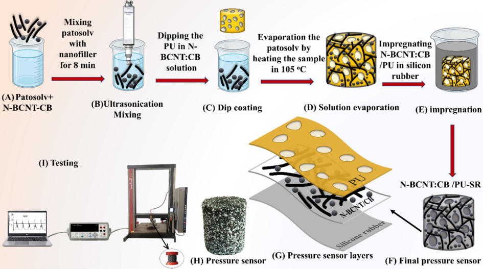
Schematic representation of the preparation steps and testing of the piezoresistive pressure sensors (N-BCNT:CB/PU-SR) which are based N-BCNT and CB as nanofillers, PU as supporting substrates, and SR. (A) Mixing N-BCNT and CB with patosolv. (B) Dispersion of N-BCNT:CB in patosolv by ultrasonication. (C) Dipping the PU samples into the N-BCNT:CB solution. (D) Patosolv evaporation. (E) Impregnation of the N-BCNT:CB/PU samples with SR. (F) Final pressure sensor. (G) Pressure sensor layers. (H) Real image of the pressure sensor. (I) Testing setup.
Then, 0.3 g of hybrid nanofiller with different mixing ratios (5:5, 6:4, 7:3, 8:2, 9:1) of N-BCNT and CB (Table 2) were dispersed in patosolv (150 ml) using Hielscher UIPHdt1000 tip homogenizer (340 W/19.42 kHz) for 8 min.
No.
N-BCNT:CB mixing ratio
N-BCNT:CB wt%
PU wt%
Silicon rubber wt%
1
5:5
0.45
4.49
95.06
2
6:4
0.46
4.41
95.13
3
7:3
0.47
4.39
95.14
4
8:2
0.44
4.41
95.15
5
9:1
0.43
4.38
95.19
Thereafter, the PU samples were immersed in the N-BCNT:CB solutions, and the treated foam samples were dried at 105 °C to evaporate the solvent and obtain the N-BCNT:CB/PU systems. In the next step, the samples were impregnated with SR under vacuum to fill the pores of the foam as much as possible and to obtain the final N-BCNT:CB/PU-SR nanocomposite pressure sensors.
3 Characterization techniques
After acid purification, the carbon content (purity) of the N-BCNT was determined by thermogravimetric analysis (TGA) using a Netzsch Tarsus TG 209 thermal microbalance. TGA measurements were performed in a mixed atmosphere (nitrogen (4.5) and oxygen (5.0)) with the flow rate set at 6 ml∙min−1 and 14 ml∙min−1 for O2 and N2, respectively. The heating rate was 10 °C min−1, in the temperature range of 35–800 °C. The binding modes of the incorporated nitrogen atoms were determined by X-ray photoelectron spectroscopy (XPS) using a SPECS Phoibos 150 MCD nine analyzer. Micro CT measurements by using a YXLON FF35 instrument (microfocus X-ray tube, transmission beam, accelerating voltage 90 kV, Al filter 0.5 mm, voxel size 15.6 µm) were performed to determine the degree of incorporation of the SR into the pores of the PU foam. The pores were analyzed using the porosity analysis/foam structure analysis modules of the VG Studio software after applying adaptive Gaussian filtering. The functional groups of the surfaces of CB and N-BCNT were identified by using a Bruker Vertex 70 Fourier-transform infrared (FTIR) spectrometer. For the measurements, the detection range was set between 4000 and 400 cm−1 with an optical resolution of 4 cm−1. All samples were dispersed in potassium bromide pellets (3 mg sample in 250 mg potassium bromide). The zeta potential of CB and N-BCNT was measured in aqueous phase with a Malvern Zeta Sizer Nano Zs instrument by using laser Doppler microelectrophoresis. The calculation of the zeta potential is based on the measurement of electrophoretic mobility according to Henry's equation.
4 Results and discussion
4.1 Characterization of the nanostructured carbon fillers
The purity (i.e., carbon content) of the N-BCNT and CB was measured by thermogravimetric analysis. Based on the TG curve of the N-BCNT, its purity is 93.0 wt% due to applied catalytic metal particles (i.e. Ni) which remained in the system (Fig. 2 A). The metal particles that catalyzed the N-BCNT growth are trapped inside the nanotubes, and the carbon layers cover them, so hydrochloric acid cannot dissolve their total amount. The CB samples were prepared by charring petrochemical oils without catalysts; thus, the purity of the char is 100%, which was confirmed by the analysis (Fig. 2 B).
TG and DTG curves of the prepared and applied N-BCNT (A) and CB (B).
The electronic properties of carbon nanotubes can be tuned by incorporating nitrogen atoms (doping) into the graphitic structure of the nanotube sidewalls. In this case, the carbon precursor was butylamine, so nitrogen atoms can be incorporated into the structure of the nanotubes. The prepared N-BCNT have been characterized by scanning tunneling spectroscopy (Czerw et al., 2001; Golberg et al., 2003; Villalpando-Paez et al., 2006). The tunneling spectra of multi-walled carbon nanotubes (MWCNT) and N-doped BCNT were compared, and it was found that in the case of MWCNTs, the valence and conduction band properties appear symmetric about the Fermi level, while in the case of N-BCNTs, an additional electronic property appears at ∼0.18 eV. It has to be noted that the presence of an electronic density of states (DOS) at the Fermi energy indicates that the N-doped material is metallic. The donor state of N-doped nanotubes is close to the Fermi level; therefore, their electronic properties are similar to those of metals (Czerw et al., 2001; Golberg et al., 2003; Villalpando-Paez et al., 2006). Moreover, the degree of electrical conductivity of N-BCNTs can be tuned in a wide range by changing the nitrogen content (Lee et al., 2009; Wiggins-Camacho and Stevenson, 2009). The incorporation of nitrogen was confirmed by XPS measurements. By the deconvolution of the N 1s band the C-N bond types are identified in the N-BCNT structure (Fig. 3 A). Three bands are found at 404.8 eV, 401.3 eV, and 398.7 eV, corresponding to the oxidized (pyridine N-oxide), graphitic, and pyridinic nitrogen, respectively. Other bonds are also detectable in the XPS spectrum. In the deconvoluted C 1s band of the nanotubes, there is a peak corresponding to the C=C bond (graphitic carbon) at 284.5 eV binding energy (Fig. 3 B). Furthermore, C=O or C-N bonds were also identified as an adsorption maximum detected at 287.6 eV. Another peak was located at 291.1 eV which can be associated with the C-O bonds in the structure. The peak corresponds to the “shake up” satellite was also found at 294 eV (P. Zhang et al., 2020b).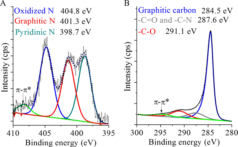
Deconvoluted N 1s band (A) and C 1s band (B) on the XPS spectrum of the prepared and applied N-BCNT.
Due to the synthesis method of CB and acid purification of the raw N-BCNT, oxygen-containing functional groups (hydroxyl (-OH), and carboxyl groups (-COOH)) are present on the surface of N-BCNT and CB, which facilitates their dispersion in the liquid phase. During the preparation of CB, water was sprayed into the reactor (water quench) in addition to the oil vapor at over 1000 °C. The resulting oxidative environment led to the formation of the above-mentioned oxygenated functional groups. The N-BCNT was partially oxidized during the purification method in the concentrated hydrochloric acid solution. The presence of these functional groups on the surface of the CB and N-BCNT were verified by infrared spectroscopy (Fig. 4 A). In the FTIR spectra, a band is located at 1065 cm−1 which can be associated with the C-O stretching vibration mode of the hydroxyl and carboxyl groups. Around 1400 cm−1 (1374 cm−1 and 1368 cm−1), the absorption peak of the βOH vibrational mode was found which can be linked to the presence of hydroxyl, and carboxyl groups, and adsorbed water. Peaks at 1631 cm−1 for N-BCNT and 1628 cm−1 for CB, were identified as νC=C stretching which can be attributed to the skeletal vibration of the CNT and the graphitic layers of the CB structure. The νC=O bands are located at 1661 cm−1, which are intertwined with the C=C bands in the case of the two nanostructured carbon forms and these peaks can be associated with carbonyl or carboxyl groups. The peaks at 2823 cm−1 and 2905 cm−1 can be attributed to the asymmetric and symmetric stretching of the C-H bonds. A broad νOH band is visible in the region around 3400 cm−1. The hydroxyl groups can be deprotonated, leading to a decrease in the zeta potential of the N-BCNT and CB samples. The negatively charged surface will stabilize the aqueous dispersion of these nanostructured carbon materials. The zeta potential of the N-BCNT and CB was measured in aqueous dispersion using a Malvern Zetasizer (Fig. 4 B). In both cases, a negative value was measured, −21.8 mV and −24.5 mV for N-BCNT and CB, respectively. The negative electrokinetic potential indicates good dispersibility of the N-BCNT and CB in water and further verifies the presence of oxygen containing groups on their surface.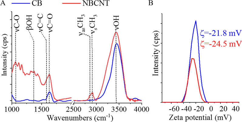
FTIR spectrum (A) and Zeta potential distribution (B) of the prepared and applied CB and N-BCNT samples.
The unusual bamboo-like structure of N-BCNT builds up from semi-fullerene-like caps so that the CNTs are divided by graphene lattices (Fig. 5 A and B). The graphene edges along the axis of the nanotube are visible at high magnification on the HRTEM image (Fig. 5 B). The above-mentioned oxygen-containing functional groups, mainly OH and COOH, which can be deprotonated, leading to a negative electrokinetic potential of the N-BCNT, are located at these edges. The negatively charged surface increases the electrostatic repulsion between the particles and improves the stability of the dispersion. In addition, these edges and the functional groups on the surface promotes to create a stronger interaction between the nanotubes and the PU matrix. The aggregated structure of CB is composed of smaller carbon particles (Fig. 5 C and D). This secondary structure can be broken down into smaller segments which are easily dispersible in the aqueous phase. The presence of hydroxyl and carboxyl functional groups on their surface contributes to their efficient dispersibility, also due to their negative surface charge, as in the case of N-BCNT.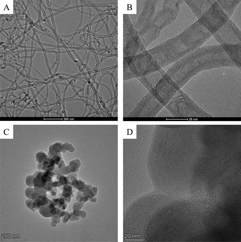
HRTEM images of the prepared and applied N-BCNT (A and B) and CB (C and D).
4.2 Electrical and piezoresistive properties
The electrical and piezoresistive properties of the prepared N-BCNT:CB/PU-SR hybrid composites were measured. The samples contained a fixed weight ratio of N-BCNT and CB (0.4 wt%) within each composite, but the mixing ratio of the nanotube and CB was different in each case (N-BCNT:CB 5:5, 6:4, 7:3, 8:2, and 9:1). The initial electrical resistance of the samples with 5:5, 6:4, 7:3, 8:2, and 9:1, N-BCNT:CB ratios were 446, 442, 308, 435, and 449 kΩ, respectively (Fig. 6). As one can see, the electrical resistance decreases when the compressive pressure is applied to the N-BCNT:CB/PU-SR samples (Fig. 6 A). In the case of the 5:5 N-BCNT:CB/PU-SR sensor, the resistance drops from 150 kΩ to 100 Ω when pressure is increased from 66 kPa to 75 kPa. Such phenomena could happen because the distance between the nanofillers becomes smaller, resulting in more conductive paths, giving the sensor higher electrical conductivity. The electrical behavior is almost identical for the samples with 5:5, 6:4, 8:2, and 9:1 N-BCNT:CB ratios. However, in case of the sensor with 7:3 N-BCNT:CB ratio, a drastic decrease in electrical resistance is observed. Thus, this mixing ratio is optimal, because the electrical conductivity is achieved its maximum due to the synergistic effect of the nanofillers. By increasing the N-BCNT:CB ratio beyond 7:3 makes it more difficult for the N-BCNT to align and expand, and also decreases the relative amount of CB, resulting in minimal contact between the fillers. On the other hand, decreasing the amount of N-BCNT reduces the ability of electrical charge transport over long distances along the aligned and extended nanotubes (Wen et al., 2012). Despite the high aspect ratio of N-BCNT, it is possible that the structure of the conductive networks is not perfect. Therefore, CB can fill the gaps between the N-BCNT to improve the electrical conductivity. This leads to a decrease in the electrical resistance of the nanocomposite. Moreover, this proves that the nanotubes are primarily involved in creating conductive networks. Thus, the N-BCNT form the backbone of the electrical conductivity of the hybrid nanofillers. The CB then fills the gaps between the N-BCNT to further improve the electrical conductivity (Wen et al., 2012).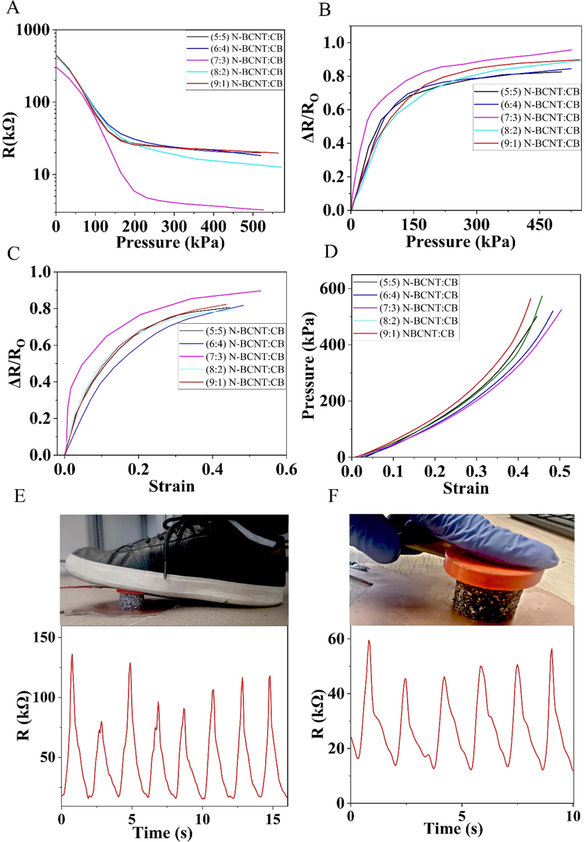
The resistance vs pressure (A), pressure sensitivity (B), gauge factor (C), and strain–stress curve (D) of the developed N-BCNT:CB/PU-SR pressure sensors with different N-BCNT:CB ratios of 5:5, 6:4, 7:3, 8:2, and 9:1. The 7:3 N-BCNT:CB/PU-SR sensor was tested in motion and finger touch detection as well (E,F).
The pressure sensitivity (S) of the sensor can be defined as the change in relative electrical resistance as a function of applied pressure. The S of the developed pressure sensors was measured (Fig. 6 B and Table 3) in different pressure ranges, and it was calculated according to following equation:
N-BCNT:CB
mixing ratio
S in the
range of 0–75 kPa−1
S in the
range of 179–525 kPa−1
GF in strain
range of
0.000–0.018
GF in strain
range of 0.14–0.43
5:5
7.8*10−3
2.9*10−4
5.00
0.59
6:4
7.1*10−3
2.9*10−4
4.00
0.40
7:3
1.3*10−2
4.0*10−4
25.00
0.69
8:2
5.4*10−3
3.6*10−4
4.67
0.49
9:1
5.7*10−3
3.0*10−4
4.70
0.60
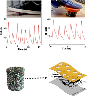
The pressure vs strain results show that the behavior of all samples is similar and the compressive pressure for all samples is in the range of 495–573 kPa under the applied strain (Fig. 6 D). The compressive strength depends on the percentage of the nanofiller, and non-silicone rubber filled area as measured by micro-CT. The sensor with the optimal 7:3 N-BCNT:CB nanofiller ratio was tested in various applications. Due to the good repeatability and sensitivity of the sensors, monitoring of human activity is also possible (Fig. 6 E, F). It can successfully record different pressure levels for various activities, such as motion detection, and finger touch detection. To measure the movement (or step-counter) and detect finger touch, the pressure sensor was placed between two electrodes and the resistance was recorded during the pressure sequence of loading and unloading. The resistance changes of the sensor were due to the tunneling of the resistance between the nanofillers and the loss of the connections between them. The peak amplitudes are indicated by the amount of pressure applied to the sensor during each movement with the finger or foot. Overall, this flexible pressure sensors have the potential to enable various touch and motion detection applications in a wide range of fields, from consumer electronics to healthcare.
4.3 Morphological characterization of the N-BCNT:CB/PU-SR system
The morphology of pressure sensor and dispersion state of nanofiller was evaluated by SEM for 7:3 N-BCNT:CB samples as shown in Fig. 7. The PU skeleton shows a wrinkled surface due to the incorporation of N-BCNT and CB (Fig. 7 A). Indicating that the N-BCNT and CB were bonded to the foam by the dip coating process. At higher magnification, the nanofiller coating on the PU structure is visible, and the CBs are close to the N-BCNT which is leading to the formation of a synergistic conductive network (Fig. 7 B). This hybrid nanofiller can efficiently improve the piezoresistive performance of nanocomposites (Ke et al., 2016), by creating a grape-cluster-like between N-BCNT and CB (Fig. 7 C, D) (Wen et al., 2012). CB acts as a bridging point between N-BCNTs and would improve the electrical conductivity and pressure sensitivity. As it is shown on the cross section of 7:3 N-BCNT:CB/ PU-SR sensor, the SR fills the pores of PU (Fig. 7 E). In addition, the SR and the N-BCNT:CB/PU can be clearly distinguished into two layers on the elemental mapping of the nanocomposite (Fig. 7 F). The green color represents N-BCNT and CB, which were deposited onto the surface of PU, while the purple color represents silicone. All in all, good adhesion was observed between the components of the nanocomposite, which is clearly reflected in the performance of the sensor.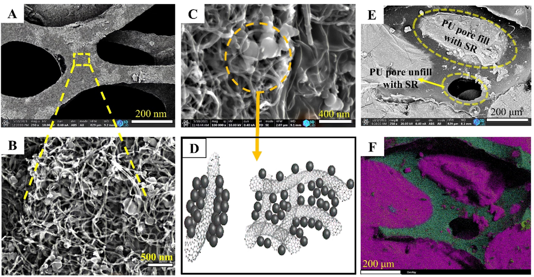
SEM image of the dispersed N-BCNT:CB on the PU skeleton (A,B), nanofiller coating of PU and the grape-cluster-like model of the hybrid N-BCNT:CB nanofiller (C,D), cross section and elemental mapping of the N-BCNT:CB/PU-SR sensor (E,F).
4.4 Structural analysis of the PU and the N-BCNT:CB/PU-SR pressure sensor
A micro-CT was used to map and characterize the cell structure of the pure PU foam and the N-BCNT:CB/PU-SR nanocomposites (Fig. 8). The pure PU had a significant amount of open porosity; these pores will later be filled with silicone rubber. The size of 90% of the total pores ranged from 50 to 1000 µm, and the average cell diameter was 620 ± 329 µm. This pore size indicates that SR can easily penetrate into the PU foam. The volume of pressure sensors which is not filled with SR was also determined (Fig. 8 C-J and Table 4). The white areas refer to the PU foam filled with SR and the blue areas refer to PU, which is not filled with silicone rubber. In general, only a small portion of the total volume is not filled with SR which is not affect the applicability of the sensors. By using better vacuum during the preparation, the volume without SR could be further decreased. If pressure is applied to the N-BCNT:CB/PU system in the absence of SR, the nanofiller may be unintentionally removed. This is because only van der Waals forces hold the system together. However, by applying SR, the position of the nanofiller is fixed and the structural integrity of the sensor is maintained.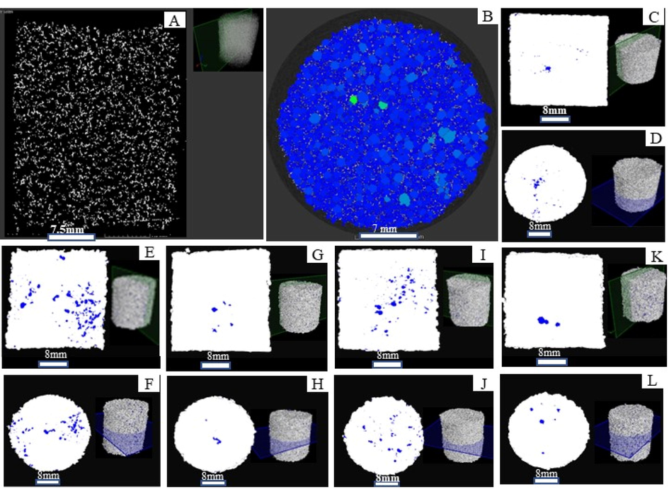
Horizontal and vertical mapping of CT plane position of pure PU (A,B), and the developed N-BCNT:CB/PU-SR pressure sensors with different N-BCNT:CB ratios of 5:5 (C,D), 6:4 (E,F), 7:3 (G,H), 8:2 (I,J), and 9:1 (K,L).
Pressure sensors
vol%
5:5 N-BCNT:CB/PU-SR
1.0
6:4 N-BCNT:CB/PU-SR
3.2
7:3 N-BCNT:CB/PU-SR
1.7
8:2 N-BCNT:CB/PU-SR
2.2
9:1 N-BCNT:CB/PU-SR
1.2
4.5 Cyclic load
The repeatability under compressive loading and unloading were investigated (Fig. 9). The strain ramped from 10% to 30%, with a hold time of two minutes after each cycle. The samples are tested in twenty compression cycles. The electrical resistance decreased with increasing pressure and returned to baseline after the pressure was removed. The signal drift may be related to that the CB and N-BCNT layers are significantly damaged at high pressure due to the increasing distance between the adjacent carbon nanofillers. These defects can disrupt the electrical conductivity of the composite, leading to a drift in the signals. The presence of microcracks may be more likely to occur during cyclic loading, as the repeated stressing of the material can lead to the formation of cracks. With the addition of CB particles, the N-BCNT network becomes more compact and forms a more stable hybrid conductive network. During compression, the CB nanoparticles can repair the damaged N-BCNT pathways by filling the gaps between the nanotubes, which is due to their greater mobility in the polymer matrix (Slobodian et al., 2018). In general, the excellent recoverability and repeatability of the pressure sensors is due to the extreme flexibility of SR and the ability of the hybrid nanofillers to establish conductive networks. Peak shoulder phenomena for all samples during cyclic load was also experienced. As shown in Fig. 10 the peak shoulder is occurred due to destruction, reconstruction, and reformation of the conductive network during cyclic load (Mersch et al., 2020). There are many factors that increase the height of the shoulder, such as the viscoelastic properties of the polymer, an unstable conductive network, and a poor dispersion state of the nanofiller (Azizkhani et al., 2019). For a sensor with a well-dispersed nanofiller, the conductive network is easier to connect, therefore, the sensor retain stability faster when pressure is applied. In contrast, the poor dispersion state of the nanofiller leads to a high peak shoulder due to the separation of the nanofiller networks. In addition, when the electrical conductivity of the sensor is much higher than the percolation threshold, a smaller peak shoulder is formed. This is because the conductive networks become more stable. The peak shoulder was lowest for the 7:3 N-BCNT:CB sensor compared to other samples (Fig. 10 H). This further verify that the synergistic effect of N-BCNT:CB is optimal at a mixing ratio of 7:3. The sensor showed a monotonically stable resistivity behavior and an almost synchronous change in electrical resistance and pressure which is due to the fact that the nanofiller forms a more uniform conductive network at this mixing ratio.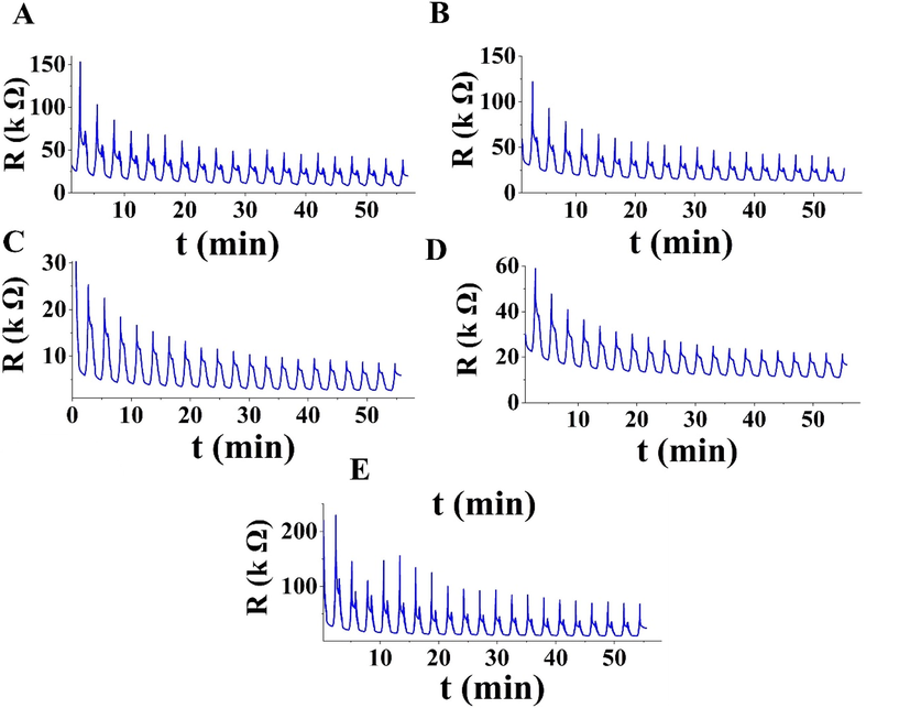
Cyclic load tests of the developed N-BCNT:CB/PU-SR pressure sensors with different N-BCNT:CB ratios of 5:5 (A), 6:4 (B), 7:3 (C), 8:2 (D), and 9:1 (E).
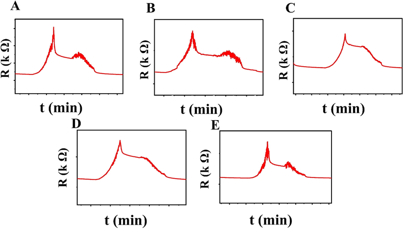
Peak shoulders of N-BCNT:CB/PU-SR pressure sensors with different N-BCNT:CB ratios of 5:5 (A), 6:4 (B), 7:3 (C), 8:2 (D), and 9:1 (E).
5 Conclusion
Pressure sensors based on N-BCNT and CB as nanofillers, PU foam as support material, and SR as a matrix were developed successfully by using a novel technology to create a prefabricated conductive network and then, impregnating it with silicone rubber. This process creates the shortest paths for electron transport through SR. The SR fabricated in this study was not subjected to any mixing process, such as ultrasonication or mixing under high shear, to achieve mixing of the nanofiller with the polymer. It is known that such mixing processes can change the physical and chemical properties of the produced polymer. The effect of using a hybrid N-BCNT:CB nanofiller was tested. The initial resistance of the N-BCNT:CB/PU-SR sensors is almost the same for the 5:5, 6:4, 8:2, and 9:1 nanotube and CB mixing ratios. However, a drastic decrease in electrical resistance is observed for the 7:3 N-BCNT:CB sample. These results indicate that the synergistic effect of the hybrid nanofiller is more pronounced in case of the 7:3 ratio. The results show excellent strain sensitivity and durability, as well as excellent recovery performance. The 7:3 sample was also successfully tested in the monitoring of human activity such as motion and finger touch detection. Thus, the preparation of the novel hybrid nanofiller and its SR nanocomposites enabled a new technology to successfully create flexible pressure sensors with excellent flexibility and good resilience. The flexible pressure sensor has demonstrated utility in motion detection and finger touch detection, making it suitable for a wide range of applications including wearable devices, prosthetics, robotic devices, and medical devices.
CRediT authorship contribution statement
Mohammed Nabeel: Investigation, Methodology, Formal analysis, Visualization, Writing – original draft, Writing – review & editing. László Kuzsella: Formal analysis, Writing – review & editing. Béla Viskolcz: Funding acquisition, Writing – review & editing. Mariann Kollar: Conceptualization, Supervision. Béla Fiser: Formal analysis, Writing – review & editing. László Vanyorek: Conceptualization, Methodology, Formal analysis, Supervision, Writing – original draft, Writing – review & editing.
Acknowledgments
This research was supported by the European Union and the Hungarian State, co‐financed by the European Regional Development Fund in the framework of the GINOP‐2.3.4‐15‐2016‐00004 project aimed at promoting the cooperation between higher education and industry. Further support was provided by the National Research, Development, and Innovation Fund (Hungary), within the TKP2021‐NVA‐14 project. The help of the members of the Polyurethane Research Laboratory (University of Miskolc) is highly appreciated.
Declaration of Competing Interest
The authors declare that they have no known competing financial interests or personal relationships that could have appeared to influence the work reported in this paper.
References
- Facile fabrication of 3d porous sponges coated with synergistic carbon black/multiwalled carbon nanotubes for tactile sensing applications. Nanomaterials. 2020;10:1-19.
- [CrossRef] [Google Scholar]
- Rheological behavior of polymer/carbon nanotube composites: An overview. Materials (Basel). 2020;13:1-27.
- [CrossRef] [Google Scholar]
- Highly sensitive, stretchable chopped carbon fiber/silicon rubber based sensors for human joint motion detection. Fibers Polym.. 2019;20:35-44.
- [Google Scholar]
- Enhanced Strain Sensing Performance of Polymer/Carbon Nanotube-Coated Spandex Fibers via Noncovalent Interactions. Macromol. Mater. Eng.. 2020;305:1900525.
- [Google Scholar]
- Facile fabrication and performance of robust polymer/carbon nanotube coated spandex fibers for strain sensing. Compos. A Appl. Sci. Manuf.. 2018;112:186-196.
- [Google Scholar]
- Identification of electron donor states in N-doped carbon nanotubes. Nano Lett.. 2001;1:457-460.
- [Google Scholar]
- Highly stretchable printed strain sensors using multi-walled carbon nanotube/silicone rubber composites. Sens. Actuators, A. 2017;259:44-49.
- [CrossRef] [Google Scholar]
- High resolution screen-printing of carbon black/carbon nanotube composite for stretchable and wearable strain sensor with controllable sensitivity. Sens. Actuators, A. 2021;332:113098
- [CrossRef] [Google Scholar]
- Structure, transport and field-emission properties of compound nanotubes: CNx vs. BNCx (x< 0.1) Appl. Phys. A. 2003;76:499-507.
- [Google Scholar]
- Crack-Across-Pore Enabled High-Performance Flexible Pressure Sensors for Deep Neural Network Enhanced Sensing and Human Action Recognition. ACS Nano 2022
- [Google Scholar]
- Three-dimensional light-weight piezoresistive sensors based on conductive polyurethane sponges coated with hybrid CNT/CB nanoparticles. Appl. Surf. Sci.. 2021;548:149268
- [CrossRef] [Google Scholar]
- A multilayered flexible piezoresistive sensor for wide-ranged pressure measurement based on CNTs/CB/SR composite. J. Mater. Res.. 2015;30:1869-1875.
- [CrossRef] [Google Scholar]
- Tuning the Network Structure in Poly(vinylidene fluoride)/Carbon Nanotube Nanocomposites Using Carbon Black: Toward Improvements of Conductivity and Piezoresistive Sensitivity. ACS Appl. Mater. Interfaces. 2016;8:14190-14199.
- [CrossRef] [Google Scholar]
- Wearable, ultrawide-range, and bending-insensitive pressure sensor based on carbon nanotube network-coated porous elastomer sponges for human interface and healthcare devices. ACS Appl. Mater. Interfaces. 2019;11:23639-23648.
- [Google Scholar]
- Highly efficient vertical growth of wall-number-selected, N-doped carbon nanotube arrays. Nano Lett.. 2009;9:1427-1432.
- [CrossRef] [Google Scholar]
- Synergy of porous structure and microstructure in piezoresistive material for high-performance and flexible pressure sensors. ACS Appl. Mater. Interfaces. 2021;13:19211-19220.
- [Google Scholar]
- Highly sensitive and stable 3D flexible pressure sensor based on carbon black and multi-walled carbon nanotubes prepared by hydrothermal method. Compos. Commun.. 2022;32:101178
- [Google Scholar]
- Highly sensitive flexible strain sensor based on carbon nanotube/styrene butadiene styrene@ thermoplastic polyurethane fiber with a double percolated structure. Polym. Eng. Sci. 2022
- [Google Scholar]
- Highly stretchable, sensitive and wide linear responsive fabric-based strain sensors with a self-segregated carbon nanotube (CNT)/Polydimethylsiloxane (PDMS) coating. Prog. Nat. Sci.: Mater. Int.. 2022;32:34-42.
- [CrossRef] [Google Scholar]
- Hierarchical carbon nanotube/carbon black scaffolds as short-and long-range electron pathways with superior Li-ion storage performance. ACS Sustain. Chem. Eng.. 2014;2:200-206.
- [Google Scholar]
- Experimental Investigation and Modeling of the Dynamic Resistance Response of Carbon Particle-Filled Polymers. Macromol. Mater. Eng.. 2020;305:2000361.
- [Google Scholar]
- Preparation of bamboo-like carbon nanotube loaded piezoresistive polyurethane-silicone rubber composite. Polymers (Basel). 2021;13
- [CrossRef] [Google Scholar]
- The Effect of Pore Volume on the Behavior of Polyurethane-Foam-Based Pressure Sensors. Polymers (Basel). 2022;14:3652.
- [Google Scholar]
- Fabrication and characterization of silicone rubber/multiwalled carbon nanotubes nanocomposite sensors under impact force. Sens. Actuators, A. 2019;297:111479
- [CrossRef] [Google Scholar]
- Multiscale Hierarchical Design of a Flexible Piezoresistive Pressure Sensor with High Sensitivity and Wide Linearity Range. Small. 2018;14:1-7.
- [CrossRef] [Google Scholar]
- Poisson effect enhances compression force sensing with oxidized carbon nanotube network/polyurethane sensor. Sens. Actuators, A. 2018;271:76-82.
- [CrossRef] [Google Scholar]
- Stretchable conductor based on carbon nanotube/carbon black silicone rubber nanocomposites with highly mechanical, electrical properties and strain sensitivity. Compos. B Eng.. 2020;191:107979
- [CrossRef] [Google Scholar]
- Comparison of rheological and electrical percolation phenomena in carbon black and carbon nanotube filled epoxy polymers. J. Mater. Sci.. 2011;46:659-669.
- [Google Scholar]
- Effect of CNTs dispersion on electrical, mechanical and strain sensing properties of CNT/epoxy nanocomposites. Results Phys.. 2019;12:486-503.
- [CrossRef] [Google Scholar]
- 3D printing of highly sensitive and large-measurement-range flexible pressure sensors with a positive piezoresistive effect. ACS Appl. Mater. Interfaces. 2020;12:28669-28680.
- [Google Scholar]
- Synthetic routes to nanoscale BxCyNz architectures. Carbon N. Y.. 2002;40:1665-1684.
- [CrossRef] [Google Scholar]
- Drastic modification of the piezoresistive behavior of polymer nanocomposites by using conductive polymer coatings. Compos. Sci. Technol.. 2015;117:342-350.
- [Google Scholar]
- Synthesis and characterization of long strands of nitrogen-doped single-walled carbon nanotubes. Chem. Phys. Lett.. 2006;424:345-352.
- [Google Scholar]
- Pressure sensing material based on piezoresistivity of graphite sheet filled silicone rubber composite. Sens. Actuators, A. 2016;252:89-95.
- [CrossRef] [Google Scholar]
- Thin flexible pressure sensor array based on carbon black/silicone rubber nanocomposite. IEEE Sens. J.. 2009;9:1130-1135.
- [CrossRef] [Google Scholar]
- Relation between repeated uniaxial compressive pressure and electrical resistance of carbon nanotube filled silicone rubber composite. Compos. A Appl. Sci. Manuf.. 2012;43:268-274.
- [CrossRef] [Google Scholar]
- Development of wireless compressive/relaxation-stress measurement system integrated with pressure-sensitive carbon black-filled silicone rubber-based sensors. Sens. Actuators, A. 2010;157:36-41.
- [CrossRef] [Google Scholar]
- Flexible and high-performance piezoresistive strain sensors based on multi-walled carbon nanotubes@ polyurethane foam. RSC Adv.. 2022;12:14190-14196.
- [Google Scholar]
- A highly flexible tactile sensor with an interlocked truncated sawtooth structure based on stretchable graphene/silver/silicone rubber composites. J. Mater. Chem. C. 2019;7:8669-8679.
- [CrossRef] [Google Scholar]
- The electrical conductivity of carbon nanotube/carbon black/polypropylene composites prepared through multistage stretching extrusion. Polymer (Guildf). 2012;53:1602-1610.
- [CrossRef] [Google Scholar]
- Effect of nitrogen concentration on capacitance, density of states, electronic conductivity, and morphology of N-doped carbon nanotube electrodes. J. Phys. Chem. C. 2009;113:19082-19090.
- [CrossRef] [Google Scholar]
- High-performance fiber strain sensor of carbon nanotube/thermoplastic polyurethane@ styrene butadiene styrene with a double percolated structure. Front. Mater. Sci.. 2022;16:1-12.
- [Google Scholar]
- Highly Sensitive Flexible Strain Sensor Based on a Double-percolation Structured Elastic Fiber of Carbon Nanotube (CNT)/Styrene Butadiene Styrene (SBS)@ Thermoplastic Polyurethane (TPU) for Human Motion and Tactile Recognition. Appl. Compos. Mater. 2022:1-16.
- [Google Scholar]
- Enhanced performance of 3D printed highly elastic strain sensors of carbon nanotube/thermoplastic polyurethane nanocomposites via non-covalent interactions. Compos. B Eng.. 2019;176:107250
- [Google Scholar]
- Multifunctional Soft Robotic Finger Based on a Nanoscale Flexible Temperature-Pressure Tactile Sensor for Material Recognition. ACS Appl. Mater. Interfaces. 2021;13:55756-55765.
- [Google Scholar]
- Comparison of Pressure Sensing Properties of Carbon Nanotubes and Carbon Black Polymer Composites. Materials (Basel). 2022;15:1213.
- [Google Scholar]
- Yuan, J., Li, Q., Ding, L., Shi, C., Wang, Q., Niu, Y., Xu, C., 2022. Carbon Black/Multi-Walled Carbon Nanotube-Based, Highly Sensitive, Flexible Pressure Sensor. ACS Omega.
- A wearable and sensitive carbon black-porous polydimethylsiloxane based pressure sensor for human physiological signals monitoring. J. Mater. Sci. Mater. Electron.. 2021;32:27656-27665.
- [Google Scholar]
- Erratum: A flexible strain sensor based on the porous structure of a carbon black/carbon nanotube conducting network for human motion detection (Sensors, (2020) 20, 1154, 10.3390/s20041154) Sensors (Switzerland) 2020
- [CrossRef] [Google Scholar]
- A flexible strain sensor based on the porous structure of a carbon black/carbon nanotube conducting network for human motion detection. Sensors. 2020;20:1154.
- [Google Scholar]
- Sensitive and wearable carbon nanotubes/carbon black strain sensors with wide linear ranges for human motion monitoring. J. Mater. Sci. Mater. Electron.. 2018;29:5589-5596.
- [Google Scholar]
- High-performance flexible strain sensors based on biaxially stretched conductive polymer composites with carbon nanotubes immobilized on reduced graphene oxide. Compos. A Appl. Sci. Manuf.. 2021;151:106665
- [Google Scholar]
- Flexible and high-performance piezoresistive strain sensors based on carbon nanoparticles@ polyurethane sponges. Compos. Sci. Technol.. 2020;200:108437
- [Google Scholar]
- Highly sensitive flexible piezoresistive pressure sensor developed using biomimetically textured porous materials. ACS Appl. Mater. Interfaces. 2019;11:29466-29473.
- [Google Scholar]


