

Translate this page into:
Electrochemical dissolution behavior of 07Cr16Ni6 alloy in sodium nitrate solution
⁎Corresponding author. wangjingtao@ujs.edu.cn (Jingtao Wang)
-
Received: ,
Accepted: ,
This article was originally published by Elsevier and was migrated to Scientific Scholar after the change of Publisher.
Abstract
07Cr16Ni6 alloy is a kind of martensitic-austenitic duplex stainless steel that is widely used in aviation and aerospace. Electrochemical machining (ECM) is an ideal manufacturing process for 07Cr16Ni6 alloy because of its high machining accuracy and good final surface quality. Studying the electrochemical dissolution behavior is pre-requisite and key to optimizing the ECM process; however, few studies have focused on the electrochemical dissolution behavior of 07Cr16Ni6 alloy. In this work, the corrosion behavior, passivation characteristics, efficiency curves, and material-removal process of 07Cr16Ni6 alloy in NaNO3 solution were comprehensively investigated. Based on the curves of potentiodynamic polarization and conductivity curve, it was found that both of them have significant passive and transpassive characteristics. The results of X-ray photoelectron spectroscopy and electrochemical impedance spectroscopy indicated that the passive film was mainly composed of Fe3O4, α-Fe2O3, γ-Fe2O3, Cr2O3, NiO, SiO, and SiO2, and its structure was composed of a dense inner-layer film and a loose outer-layer film. A schematic model was proposed to characterize the interface structure between the 07Cr16Ni6 alloy, the passive film and electrolyte. ECM tests were performed at different current densities and for different corrosion times. The current-efficiency results indicate that the material-removal rate can be divided into three regions. The current efficiency first rises gently, then rises steeply once the current density exceeds 26 A cm−2; it finally remains stable at current densities greater than 45 A cm−2. The corrosion morphology exhibits loose, blocky bulges at low current density, while the surface exhibits lath-type martensite structures when the current density j > 15 A cm−2. The material-dissolution process of the 07Cr16Ni6 alloy in NaNO3 solution at 20 A cm−2 was presented. Finally, a model of dissolution was established to characterize the electrochemical dissolution of the 07Cr16Ni6 alloy in NaNO3 solution.
Keywords
Electrochemical dissolution behavior
07Cr16Ni6 alloy
Passive film
XPS
EIS

1 Introduction
07Cr16Ni6 alloy is a type of martensitic-austenitic duplex stainless steel, has some inherent advantages, such as high strength and toughness, good ductility, a low notch sensitivity, excellent low temperature performance, good weldability, and corrosion resistance in various aggressive environments (Tian et al., 2017). 07Cr16Ni6 alloy is key materials for heavy load components and transmission components in the chemical, nuclear, aerospace, and aviation industries. 07Cr16Ni6 alloy is typical difficult-to-cut materials. However, manufacturing process of the 07Cr16Ni6 alloy via mechanical cutting techniques has many problems because of their high specific strength and hardness, such as microcracks, chipping edges and high processing costs.
Electrochemical machining (ECM) is classified as a typical nontraditional manufacturing method that removes anode materials via electrochemical anodic dissolution reaction (Xu and Wang, 2021; Painuly et al., 2023). It has some inherent advantages, such as independence on the physical properties of the material itself, the absence of tool wear, no residual stress, no recast layer and microcrack, high efficiency, and low-cost for mass production of components. These advantages make it a preferred method for use in critical parts made of the difficult-to-cut conductive materials in aviation and aerospace industry. It has successfully manufactured blades (Ren et al., 2023); blisks (Wang et al., 2023), gearbox (Cao et al., 2022), and other components (Meng et al., 2017). Considering the advantages of ECM, it is the preferred processing method for 07Cr16Ni6 alloy parts.
The electrochemical dissolution behavior is a pre-requisite and key to ECM process, which is helpful to select processing parameters and grasp the forming law of components, as this influences the processing accuracy and surface quality. The electrochemical dissolution behavior of the stainless steel has been frequently studied in recent years. Give an example, Wang et al. (Wang et al., 2015) analyzed the electrochemical dissolution property of 304 stainless steel in NaNO3 solution at low current densities, and found that machined surface presented a complete surface protected by a compact passive film. Pradhan et al. (Pradhan et al., 2021) conducted the influence of various microstructural attributes (i.e, grain size, residual strain) as well as the implication of sensitization on the electrochemical response and passive film behavior of 304 stainless steel. They reported that the defects induced via straining depreciated the protectiveness of passive film. Shi et al. (Shi et al., 2020) reported the chloride-induced corrosion behavior and the pitting corrosion resistance of 2304 duplex stainless steel in carbonated solutions, and the results showed that the passive film properties and chloride-induced corrosion was remarkably affected by carbonation. Wang et al. (Wang and Qu, 2020) focused on the electrochemical dissolution behavior of S-04 high-strength stainless steel in NaNO3 solution. They reported that the machined surface was covered with black matter, and the black surface was mainly due to the presence of Fe3O4. An et al. (An et al., 2022) conducted a study on the electrochemical tests including current efficiency, open circuit potential, and polarization behavior of the 316L stainless steel fabricated by laser powder bed fusion in NaNO3 solution, and found that electrochemical dissolution of the transverse section is more difficult than the longitudinal section. Lodhi et al. (Lodhi et al., 2018) and Al-Mamun et al. (Al-Mamun et al., 2020) observed the chemical composition and corrosion response of the passive film of the 316L stainless steel in acidic regime (pH ≤ 3), and found that the formation of mono layered and bi layered passive film in pH 1 and 3 electrolytes, respectively. In addition, Kishore et al. (Kishore et al., 2022) investigated the effect of strain-rate in conjunction with pre-strain during forming of 304L stainless steel on electrochemical corrosion. They reported that the corrosion behavior of 304L stainless steel is a stronger function of strain-rate, and corrosion resistance was improved at a high strain-rate.
The above research provides a sound understanding of the electrochemical dissolution behavior of stainless steel. However, the reference value of these studies for 07Cr16Ni6 alloy is limited. Moreover, little is known about the dissolution properties and corrosion response of the passive film on 07Cr16Ni6 alloy in NaNO3 solution. Therefore, in this work, the electrochemical dissolution behavior of 07Cr16Ni6 alloy in NaNO3 solution was systematically investigated.
First, the phase composition of the 07Cr16Ni6 alloy was analyzed by X-ray diffraction (XRD). Second, the passive–transpassive transition behaviors were determined by potentiodynamic polarization and measurement of the open-circuit potential (EOCP). It was found that the 07Cr16Ni6 alloy exhibits significant passive and transpassive characteristics. Third, the chemical composition and the interface structure of the passive film of the 07Cr16Ni6 alloy in NaNO3 solution were examined by X-ray photoelectron spectroscopy (XPS) and electrochemical impedance spectroscopy (EIS). The results show that the chemical composition of the passive film includes mainly Fe3O4, α-Fe2O3, γ-Fe2O3, Cr2O3, NiO, SiO, and SiO2, and its structure is composed of a dense inner-layer film and a loose outer-layer film. The current efficiency of the 07Cr16Ni6 alloy in NaNO3 solution was measured, and ECM-based dissolution tests were subsequently performed at different current densities and for different corrosion times to investigate the process of material removal. The surface quality, surface morphology, and composition of the dissolved surfaces were observed using a confocal laser scanning microscope, a scanning electron microscope (SEM), and energy-dispersive X-ray spectroscopy (EDX). It was found that the surface roughness first decreases rapidly and then remains basically constant. The corrosion morphology exhibits loose, blocky bulges at low current density, while it exhibits lath-type martensite structures when the current density j > 15 A cm−2. Finally, a corresponding model of the electrochemical dissolution of 07Cr16Ni6 alloy in NaNO3 solution was established.
2 Experimental details
2.1 Specimens
The workpiece material was 07Cr16Ni6 alloy, and specimens with edges ∼ 10 mm were machined by wire electrical discharge machining to conduct electrochemical measurements and perform ECM experiments. To eliminate the effects of the recasting layer, the surfaces of the specimens were sanded using a metallographic pre-grinder machine and then mechanically polished using a metallographic polishing machine. Finally, the 07Cr16Ni6 specimens were ultrasonically cleaned sequentially with deionized water and ethanol, and they were subsequently dried in air. To better indicate the dissolved morphology of the 07Cr16Ni6 specimens, an original SEM micrograph before electrochemical treatment is provided in Fig. 1. In SEM measurements, secondary electron image (SEI) model was selected to carry out SEM observations. The acceleration voltage and the working distance were set to 20.0 kV and 11 mm, respectively. The magnification of SEM images was set to 400 ×.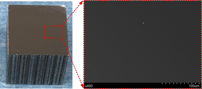
Micrographs of 07Cr16Ni6 alloy before ECM.
The chemical composition of the 07Cr16Ni6 specimens was measured via EDX (XFlash 5010, Bruker, Germany), and the results are listed in Table 1. These results show that in addition to Fe, Cr, and Ni, the 07Cr16Ni6 alloy also contains Si, Mn, and Ti. To better understand the dissolution mechanism of the 07Cr16Ni6 alloy in NaNO3 solution, phase composition was investigated via XRD (DS Advance, Bruker, Germany) with Cu K-alpha radiation (λ = 1.5406 Å) at 40 kV and 40 mA, and the 2θ scanning range was from 30° to 80° with a scanning rate of 5 deg./min. As illustrated in Fig. 2, it can be seen that the peaks of the α phase, which has a body-centered cubic structure, are presented at 2θ = 44.69° and 64.81° in the 07Cr16Ni6 sample (Saeidi et al., 2019). In addition, peaks from the γ phase, which can be considered as retained austenite, are also present at 2θ = 43.78°, 50.93°, and 74.92° (Ravi et al., 2013). The austenite content was measured using a Feritscope (Fischer Instrumentation), and its volume fraction was found to be approximately 12 wt%; the balance was martensite.
Species
Cr
Ni
Si
C
Mn
Ti
Fe
Content
16.4
6.75
0.62
0.06
0.45
0.03
Bal.
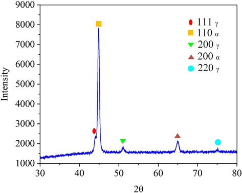
XRD spectrum of the 07Cr16Ni6 alloy.
2.2 Electrochemical measurements
Electrochemical polarization behavior was evaluated using a standard three-electrode system on an electrochemical workstation (CHI660E, Chenhua, China), as shown in Fig. 3. A platinum electrode (20 × 20 × 0.2 mm) was used as the counter electrode (CE). A calomel electrode was used as reference electrode (RE), and the reference solution was saturated KCl solution. The 07Cr16Ni6 specimen was used as the working electrode (WE), and this was embedded into epoxy resin to mask five of its faces, leaving an exposed surface area of 100 mm2. NaNO3 electrolyte has some inherent advantages, such as inexpensive, non-toxicity, non-corrosiveness, good maintainability, etc. In the meantime, NaNO3 is the blunt nonlinear electrolyte, which can enhance the localization effect and improve performance of the ECM process (Thangamani et al., 2021). These advantages make NaNO3 electrolyte a better and more economical alternative for use in ECM process. The solution was prepared with deionized water and analytically pure NaNO3 electrolyte. The electrolyte concentrations are 1 wt%, 5 wt%, 10 wt%, 15 wt%, 20 wt% at 35 ℃; and the electrolyte temperatures are 5 ℃, 15 ℃, 25 ℃, 35 ℃, 45 ℃, 55 ℃ at 15 wt%. The detailed electrochemical measurements were performed in a 15 wt% NaNO3 solution at 25 °C. All the experiments were placed in an electric constant-temperature water bath, the temperature of which could be adjusted in real time.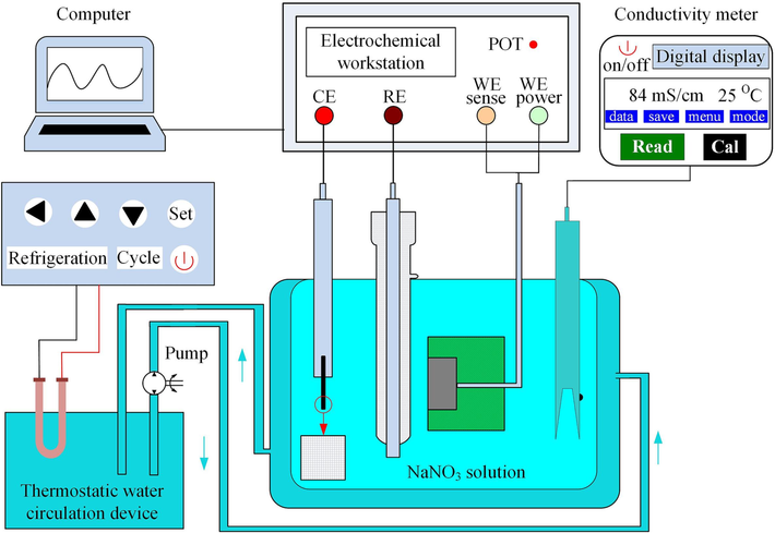
Schematic diagram of polarization behavior measuring device.
First, the EOCP of the 07Cr16Ni6 alloy was measured for 7500 s in NaNO3 solution. Next, its electrochemical polarization behavior was examined in a potential range of −2 to +4 V in NaNO3 solution at different concentrations and temperatures, and two scan rates, 5 and 1 mV/s, were used. Meanwhile, the variation of the electrolyte conductivity was also measured using conductivity meter (S230, SevenCompact, Mettler Toledo, Switzerland) during the electrochemical measurements. In addition, EIS was then performed by frequency sweeping the range from 100 kHz to 10 MHz with a 5-mV sinusoidal signal to characterize the physical structure of the passive film. Finally, XPS (K-Alpha, Thermo Scientific, USA) was carried out with a monochromatic Al Ka (1486.6 eV) radiation source by AXIS SUPRA + spectrometer (AXIS Supra™, Kratos, Japan) to analyze the chemical composition of the passive film formed on the 07Cr16Ni6 surface in NaNO3 solution. The lens mode and the analyser mode were set to standard and constant analyzer energy, respectively. Meanwhile, the pass energy was set to 30.0 eV. The C 1 s peak from adventitious carbon at 284.8 eV was used as a reference to correct the charge shifts. Before each EIS and XPS measurement, 07Cr16Ni6 specimens were subjected to potentiostatic polarization under the passivation potential in NaNO3 solution to ensure that the 07Cr16Ni6 surface was stable and so that a stable passive film could form.
2.3 ECM measurements
ECM experiments were performed with the 07Cr16Ni6 alloy in NaNO3 solution to reveal the material-removal process. A self-designed ECM system (see Fig. 4) was used; this consists primarily of an electrolyte circulation–filtration module, a temperature-control unit, a power supply, a motion-control module, and a machining cell. The 07Cr16Ni6 specimens were again embedded in epoxy resin to mask five of their faces, leaving an exposed processing surface of 100 mm2 in the NaNO3 solution. The material of the tool electrode is 1Cr18Ni9Ti, and the chemical composition (in wt.%) is C-0.112, Si-0.676, Mn-1.335, S-0.028, P-0.032, Cr-17.605, Ni-9.331, Ti-0.302, and Fe-balance. The machining gap between the 07Cr16Ni6 workpiece and cathode was adjusted by operating the motion-control module, and the initial machining gap was 0.5 mm. The electrolyte circulation–filtration module was used to move the electrolyte at a certain temperature and pressure through the machining area, and this also filtered out the dirty electrolyte over time. After ECM preparation, the surface roughness, surface morphology, and composition of the corrosion surfaces formed at different current densities and over different time periods were investigated using confocal laser scanning microscopy (OLS4100; Olympus, Japan), SEM (S-3400 N, Hitachi, Japan), and EDX.
Schematic diagram of the ECM experimental system.
3 Characteristics of electrochemical dissolution
3.1 Potentiodynamic polarization curves
The effects of temperature and the concentration of the NaNO3 solution on the characteristics of electrochemical dissolution of the 07Cr16Ni6 alloy were determined using polarization curves. The polarization curves were measured between −1 and +3 V with a scan rate of 5 mV/s through linear-sweep voltammetry. Fig. 5(a) and 5(b) show the effects of the electrolyte temperature and concentration on the characteristics of electrochemical dissolution, respectively. It can be observed that the polarization behavior of the 07Cr16Ni6 alloy at different electrolyte temperatures and concentrations exhibits obvious passive–transpassive characteristics due to the formation of a corrosion-resistant passive film during polarization. The transpassive potential (Etrans) was defined as the breakdown potential, at which the passive film starts to rupture. Note that increasing the electrolyte temperature and the concentration of the NaNO3 solution cause slight decreases in the Etrans values. This is because the higher the concentration of the NaNO3 solution, the greater the number of reactive ions, the faster their exchange rate, and the higher the electrolyte conductivity (Duan et al., 2023). Furthermore, a higher NaNO3 solution temperature favors the kinetics of the corrosion reaction, and especially the exchange rate of the reactive ions; this is because the anodic current density increases with increasing temperature. In addition, it was clearly observed that the slopes of the polarization curves become ohmic when the voltage exceeds Etrans. This reveals that the passive film has ruptured completely at this stage. The slopes of the polarization curves also increase with increasing electrolyte temperature and concentration when the voltage exceeds Etrans; this reveals that the ohmic resistance decreases with increasing electrolyte temperature and concentration.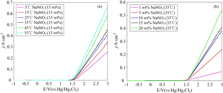
Polarization curves of the 07Cr16Ni6 alloy at different NaNO3 solution (a) temperatures and (b) concentrations.
To better characterize the passive and transpassive properties of the 07Cr16Ni6 alloy in NaNO3 solution, the detailed polarization behavior was studied under polarization potentials from −2 to +4 V with a scan rate of 1 mV/s. Fig. 6 shows the potentiodynamic polarization curves of the 07Cr16Ni6 alloy in 15 wt% NaNO3 solution at 25 °C, demonstrating an active–passive–transpassive transition. It should be noted that the polarization curve of the 07Cr16Ni6 alloy is characterized by a distinct potential domain of passivity. The current density remains close to zero when the polarization potential is between the corrosion potential (Epp, −642 mV) and Etrans (1272 mV) in 15 wt% NaNO3 solution at 25 °C, and the potential range of passivation (ΔE) is about 1914 mV. This implies good protection efficiency of the 07Cr16Ni6 alloy in NaNO3 solution and that one or more layers of passive film were formed on the 07Cr16Ni6 surface due to the passivation effect of NaNO3 solution. In this case, the current density hardly changes.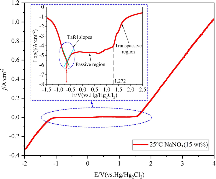
07Cr16Ni6 polarization curves in 15 wt% NaNO3 solution at 25 °C.
After reaching Etrans, the current density increases exponentially with increasing polarization potential, resulting in a pronounced anodic metal-dissolution process. This clearly indicates that the passive film begins to rupture, and a larger of the 07Cr16Ni6 matrix material is exposed to the NaNO3 solution. After that, the process enters the transpassive region, the dissolution becomes violent, and the relationship between the polarization potential and the current density is approximately linear.
In addition, to further evaluate the corrosion characteristics of the 07Cr16Ni6 alloy in 15 wt% NaNO3 solution at 25 °C, electrochemical parameters such as the corrosion current density (icorr) and corrosion potential (Ecorr) were obtained from the polarization curves. The polarization resistance (Rp) value was estimated based on the Stern–Geary equation (Wang et al., 2022; Sherif et al., 2019):
The corresponding data are summarized in Table 2. Generally, the polarization resistance can be used to characterize the corrosion resistance of the anode material. The calculated Rp value of the 07Cr16Ni6 alloy in 15 wt% NaNO3 solution at 25 °C is 2.42 × 10⁵ Ω/cm2, implying that the corrosion-resistance effect of 07Cr16Ni6 alloy is high; this high Rp is attributed to the existence of a stable passive film with incorporated oxides.
Specimen
icorr (μA/cm2)
Ecorr
(mV)
βa (V/decade)
βc (V/decade)
Rp
(Ω/cm2)
Value
9.41
−642
0.127
−0.124
2.42 × 10⁵
To better characterize the polarization behavior of the 07Cr16Ni6 alloy, the variation of the electrical conductivity of 15 wt% NaNO3 solution at 25 °C was measured during electrochemical measurements under polarization potentials from −2 to +4 V with a scan interval of 0.5 V. Fig. 7 shows the transition of the electrolyte electrical conductivity from steady to steep behavior. This phenomenon is also in accord with the polarization curves. It can be observed that the slope of the electrolyte electrical conductivity become steeper when the polarization potential exceeds 1.17 V. This is because when the polarization potential exceeds Etrans (i.e. the breakdown potential), the passive film begins to rupture, the matrix material begins to dissolve, the concentration of reactive ions in the free state increases, and the exchange rate of the reactive ions becomes faster. As a result, the electrolyte electrical conductivity begins to increase.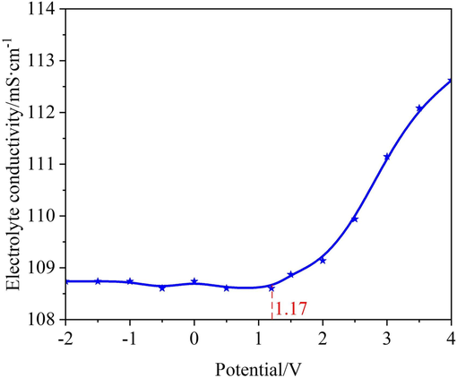
Dependence of electrolyte electrical conductivity on the polarization potential of the 07Cr16Ni6 alloy during electrochemical measurements.
3.2 Open-circuit potentials
Representative plots of EOCP versus time for the 07Cr16Ni6 alloy in 15 wt% NaNO3 solution at 25 °C were obtained after a reverse voltage was applied at −1 V to eliminate the initial oxide film formed in the air. Fig. 8 presents the time dependence of the EOCP value for the 07Cr16Ni6 alloy in NaNO3 solution. It can be seen that EOCP decreases gradually with time. One possible explanation for this is that the residual oxide film begins to rupture by reverse polarization. The value of EOCP reaches a minimum at 669 s, which is approximately −0.11 V in 15 wt% NaNO3 solution at 25 °C; the EOCP value then tends to be stable. This is because the 07Cr16Ni6 alloy contains 16.4 % chromium, which is a passivable element. Thus, during the EOCP test, a passive film containing Cr2O3 grew on the 07Cr16Ni6 alloy surface, shifting the EOCP value to a stable potential. These phenomena are nearly consistent with those observed by Al-Mamun et al. (Al-Mamun et al., 2020).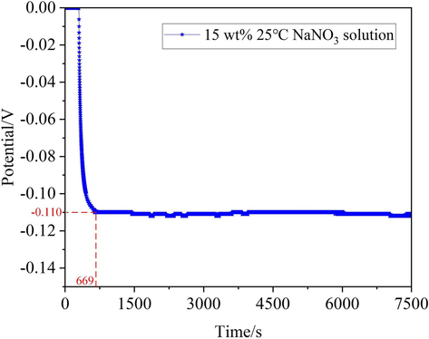
Plot of EOCP of the 07Cr16Ni6 alloy over time in 15 wt% NaNO3 solution at 25 °C.
3.3 Chemical composition of passive film
To better understanding of passive film formed on the 07Cr16Ni6 surface in 15 wt% NaNO3 solution at 25 °C, the 07Cr16Ni6 specimens were tested by using potentiostatic polarization at passivation potential of 1.0 V for 1800 s, and so that a passive film could form. To further explore the chemical properties of this passive film, XPS analysis was used. The test mainly focused on the metallic elements in the passive film (such as Fe, Cr, Ni, and Si). The wide XPS spectrum of the passive film is shown in Fig. 9(a). C 1 s, O 1 s, Fe 2p, Cr 2p, Ni 2p, and Si 2p peaks were detected. Fig. 9(b) shows high-resolution spectra of Fe 2p, which is decomposed into five components. The three peaks at binding energies of 709.7, 706.3, and 719.4 eV represent Fe3O4, Fe, and γ-Fe3O4, respectively. In addition, the two peaks at binding energies of 711.1 and 724.1 eV represent α-Fe2O3 (Wang and Qu, 2020; Wang et al., 2022). The Cr 2p spectrum contains peaks at binding energies of 575.6 and 587.0 eV (Fig. 9(c)), which represent Cr2O3 (Wang et al., 2021). The binding energy of 583.3 eV is consistent with that of Cr. The spectrum of Ni 2p is decomposed into three peaks (see Fig. 9(d)). The peaks at binding energies of 855.8, 860.6, and 873.6 eV correspond to NiO. Fig. 9(e) indicates that Si 2p is decomposed into two peaks at binding energies of 101.9 and 103.2 eV, corresponding to SiO and SiO2, respectively (Filatova et al., 2023). These results show that Fe3O4, α-Fe2O3, γ-Fe2O3, Cr2O3, NiO, SiO, and SiO2 are the main components of the passive film of the 07Cr16Ni6 alloy in 15 wt% NaNO3 solution at 25 °C. In addition, some oxides of Ti and Mn may also exist in the passive film, but these are hardly detected due to their small quantities.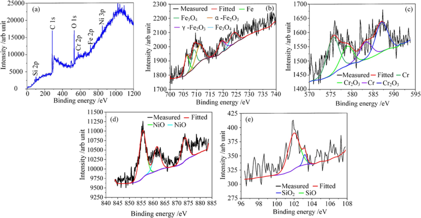
XPS spectra of the passive film formed on the 07Cr16Ni6 surface in NaNO3 solution: (a) survey-scan peaks; (b) high-resolution Fe 2p spectra; (c) high-resolution Cr 2p spectra; (d) high-resolution Ni 2p spectra; (e) high-resolution Si 2P spectra.
Table 3 summarizes the compositions of the passive film as determined from integration of the XPS data. The results show that the percentage content of Cr2O3 (29.9 %) is very high in the passive film, which reflects a dense, stable, and protective structure. It is worth noting that the passive film also contains 20.5 % NiO, which reflects a loose and porous structure. Previous studies have shown that a passive film rich in Cr2O3 is compact, stable, and highly protective (Wang et al., 2022). Conversely, a film rich in NiO has a loose structure and low protective capability (Wang et al., 2021; Zhang et al., 2022). Therefore, it can be assumed that the passive film can be classified as a bi-layer film, and high percentage contents of Cr2O3 will cause a dense inner-layer film, and high percentage content of NiO will cause a loose outer-layer film. We further verified the characteristics of the bi-layer film via EIS.
Species
Fe3O4
α-Fe2O3
γ-Fe2O3
Cr2O3
NiO
SiO
SiO2
Content
10.3
25.2
10.1
29.9
20.5
3.7
0.3
3.4 Bi-layer structure of passive film
The electrochemical properties of the passive film for the 07Cr16Ni6 alloy in NaNO3 solution were clarified based on EIS response. EIS tests were analyzed using the ZView software package (CS Studio, version 5.2). Fig. 10 shows EIS plots for the 07Cr16Ni6 alloy in NaNO3 solution, including Nyquist and Bode plots. The Nyquist plot (see Fig. 10(a)) exhibits a typical capacitive semi-loop shape, which is related to charge-transfer processes at the electrolyte/electrode interface (Xiao et al., 2013). This behavior suggests that the electrochemical dissolution mechanism of the 07Cr16Ni6 alloy in NaNO3 solution is dominated by the passive film. For the Bode impedance spectrum (blue line) in Fig. 10(b), the value of impedance represents the polarization resistance of the 07Cr16Ni6 alloy. The results show that the impedance modulus of the 07Cr16Ni6 alloy increases rapidly from high to low frequencies. The Bode impedance in the low-frequency region is used to assess the corrosion resistance of the material (Chen et al., 2014). The low-frequency Bode impedance for the 07Cr16Ni6 alloy in NaNO3 solution is relatively high. This is attributed to the passive film formed on the 07Cr16Ni6 surface, which acts as a physical barrier between the matrix material and the electrolyte. This can also be verified from the Bode phase spectrum (red line) in Fig. 10(b), in which the phase angles are very close to 0° around 100 kHz, indicating that the impedance in the high-frequency region was mainly determined by local surface defects and electrolytic resistance. This can also be seen from the multiple peak phase angles in the Bode phase spectrum, which indicate the presence of multiple time constants (Tang and Xu, 2018). The multiple peak phase angles suggest that a non‐ideal passivating system is present in the mid-frequency region, since the largest phase angle of the 07Cr16Ni6 alloy remained very close to −80° over a wide range of frequency. This can be attributed to the formation of a more stable passivation layer on the 07Cr16Ni6 surface.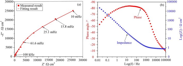
EIS plots for 07Cr16Ni6 alloy in NaNO3 solution: (a) Nyquist plot, (b) Bode plot including phase and impedance.
Based on this EIS analysis, the passive film of the 07Cr16Ni6 alloy in NaNO3 solution can be considered to be composed of an inner-layer film and an outer-layer film. Many scholars have reported that the passive film of duplex stainless steel has a two-layer structure (Pan et al., 1998; Pugal and Raiendran, 2017; Freire et al., 2011). For further insights into the physical structure of the passive film, an electrical equivalent circuit (EEC) model with multiple time constants was used to fit the EIS data. A constant-phase element (CPE) was used to describe the non-ideal capacitive behavior. In the EEC model: CPEf1 and CPEf2 represent the capacitances of the inner- and outer-layer films, respectively; Rs represents the solution resistance between the WE and RE; Rct and Qdl represent the charge-transfer resistance and the capacitance of the electrode/solution interface, respectively; Qf1 and Qf2 represent the diffusion capabilities of ionic species in the inner- and outer-layer films, respectively; Rf1 and Rf2 represent the protective properties of the inner- and outer-layer films, respectively. Normally, a high Rct and small Qdl indicates that the 07Cr16Ni6 surface is very stable and in an equilibrium state, and its corresponding ionic activity is very slow, which means that the 07Cr16Ni6 alloy in NaNO3 solution has high corrosion resistance.
The EEC fitting parameters are listed in Table 4. The goodness of fit, estimated from the chi-squared (χ2) values, was found to be of the order of 10−3. This indicates that this model is compatible with the electrode system in our current study. There are significant differences between Rf and Qf for the 07Cr16Ni6 alloy as measured in the NaNO3 solution. It can be observed that the values of Rf2 and nf2 are much larger than the values of Rf1 and nf1; furthermore, the value of Qf2 is smaller than that of Qf1. This implies that the outer-layer film is looser than the inner-layer film, and it offers weaker protection and higher diffusion capabilities. The Rp values of the 07Cr16Ni6 alloy in NaNO3 solution can be obtained by the addition of Rct, Rf1, and Rf2 (Rp = Rf1 + Rf2 + Rct). From this, the value of Rp obtained from EIS was found to be 2.42 × 10⁵ Ω/cm2, which is in good agreement with the Rp value from the extrapolated Tafel plot (see Section 3.1). Based on the XPS and EIS analysis, a schematic model containing both the dense inner-layer film and the loose outer-layer film is proposed to observe the interface structure of the 07Cr16Ni6 alloy in NaNO3 solution (see Fig. 11).
Specimen
Rs
Ω/cm2
Qf1
μF/cm−2
nf1
Rf1
Ω/cm2
Qf2
μF/cm−2
nf2
Rf2
Ω/cm2
Qdl
μF/cm−2
ndl
Rct
Ω/cm2
χ2
Value
2.345
84
0.69
29,663
55.6
0.88
147,630
79.6
0.94
64,821
2.61 × 10⁻³
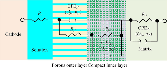
Proposed interface structure for the 07Cr16Ni6 alloy in NaNO3 solution.
4 Analysis of ECM results
4.1 Curves of current efficiency
The current efficiency is a key processing parameter of ECM. The current efficiency of the 07Cr16Ni6 alloy was investigated for current densities in the range from 1 to 80 A cm−2 in 15 wt% NaNO3 solution at 25 °C. Before each electrochemical test, the 07Cr16Ni6 specimens were ultrasonically cleaned, and then dried. Finally, they were carefully weighed using a high-precision balance (ME204E, Mettler Toledo, Switzerland) with a precision of 10−4 g. All weighing tests were repeated at least three times to ensure repeatability. During the tests, the dissolution time was fixed, and the current efficiency was calculated as follows:
As the 07Cr16Ni6 alloy is composed of multiple metal elements, the value of k can be described by the following equation:
Fig. 12 shows the current-efficiency curve of the 07Cr16Ni6 alloy in 15 wt% NaNO3 solution at 25 °C based on Eq. (2). It can be clearly observed that the current efficiency of the 07Cr16Ni6 alloy can be divided into three regions. To be more specific, the current efficiency first rises gently, then rises steeply once the current density exceeds about 26 A cm−2; it finally remains stable at current densities greater than about 45 A cm−2. In region I, the current efficiency rises gently with increasing current density. This is attributed mainly to oxygen evolution, and this period consumes the most power (Wang and Qu, 2020). With increasing current density, the predominant electrochemical reaction quickly changes from oxygen evolution to matrix-material dissolution. Thus, the current efficiency increases quickly. As the current density enters region Ⅲ, the current efficiency becomes stable. One possible explanation for this is that a large current density results in increases in the rupture rate of the passive film and the dissolution rate of the matrix material. The current efficiency of the 07Cr16Ni6 alloy in 15 wt% NaNO3 solution was approximately 0.84, which indicates that ECM is indeed a method with high processing efficiency for manufacturing 07Cr16Ni6 alloy components.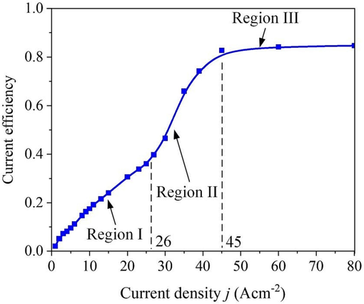
Current efficiency of the 07Cr16Ni6 alloy in 15 wt% NaNO3 solution at 25 °C.
4.2 Surface microstructure at different current densities
To further investigate the characteristics of electrochemical dissolution of the 07Cr16Ni6 alloy in 15 wt% NaNO3 solution at 25 °C, ECM experiments with different current densities and corrosion times were carried out. After electrochemical corrosion, the surface roughness, surface morphology, and composition of the corrosion surface were analyzed. Fig. 13 shows the machined surfaces of the 07Cr16Ni6 alloy samples at current densities of 5, 15, 35, and 55 A cm−2. It can be seen that 07Cr16Ni6 surface at current densities of 5 and 15 A cm−2 in NaNO3 solution exhibits seriously selective corrosion. A closer inspection shows that many loose, blocky bulges and grain-boundary corrosion appear on the corrosion surface, leaving an uneven dissolved surface. One problem with these blocky bulges is that they mean that the surface roughness of the 07Cr16Ni6 alloy is poor, Ra = 1.475 µm. This implies that the material dissolves very unevenly when j ≤ 15 A cm−2.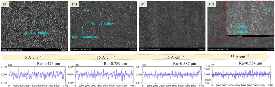
SEM images of the 07Cr16Ni6 at different current densities in 15 wt% NaNO3 solution (a) 5 A cm−2, (b) 15 A cm−2, (c) 35 A cm−2, and (d) 55 A cm−2.
With increasing current density, the blocky bulges decrease gradually, almost disappearing, leaving a patterned smooth surface with lath-type martensite structures. When the current density is 55 A cm−2, the surface roughness Ra = 0.534 µm. This indicates that the dissolution surface of the 07Cr16Ni6 alloy becomes uniform, and its surface quality is greatly improved. The SEM results thus show that a reduction in the number of blocky bulges on the surface can improve the surface quality. In addition, the chemical compositions of the blocky bulges and the lath-type martensite structures were determined by EDX. Fig. 14 shows the measurement results from the areas marked “A” and “B”, representing blocky bulges and lath-type martensite structures, respectively. The results reveal that some Cr, Fe, and Ni oxide precipitates form at the loose blocky bulges and the lath-type martensite after the corrosion experiments.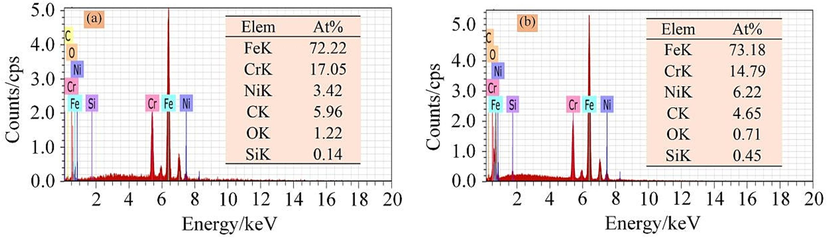
EDX results: (a) blocky bulges and (b) lath-type martensite structures.
The internal relationship between the surface roughness of the 07Cr16Ni6 alloy and the current density was analyzed in 15 wt% NaNO3 solution at 25 °C. Fig. 15 shows the variation of the surface roughness of the 07Cr16Ni6 alloy with current density in 15 wt% NaNO3 solution. The curve shows that the roughness decreases sharply when j < 20 A cm−2. This indicates that the surface quality obtained through the electrochemical dissolution of the 07Cr16Ni6 alloy is highly dependent on current density in ECM process. Above this value, the surface roughness only changes slightly, and comparisons showed that the machined surface became smoother. It is thus further verified that ECM at a high current density is indeed the preferred method for processing 07Cr16Ni6 alloy components with high current efficiency and good surface quality.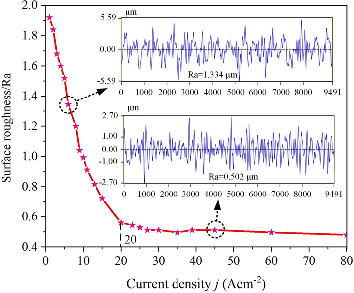
Surface roughness of the 07Cr16Ni6 alloy under various current densities.
4.3 Material-removal process
In this section, the material-removal process of the 07Cr16Ni6 alloy was examined with a current density of 20 A cm−2 in 15 wt% NaNO3 solution at 25 °C. As can be seen from Fig. 16, when the corrosion time is 5 s, the passive film is dissolved, and the 07Cr16Ni6 exhibits serious pitting corrosion. In this state, electrochemical dissolution of the 07Cr16Ni6 surface is quite weak, and scratches appear clearly. As the dissolution time was increased, grain-boundary corrosion occurred rapidly due to the higher energy state, surface scratches were mostly removed, and the lath-type martensite structures became more prominent. A longer dissolution time of 80 s gives a flat corrosion surface with many lath-type martensite structures and trace austenite structures, leading to an improved surface. For a machining time of 320 s, the corrosion surface undergoes no further changes. It is important to note that no significant improvements in surface quality occur upon increasing the machining time.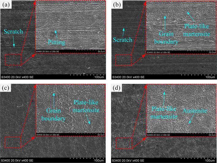
SEM images of the 07Cr16Ni6 after different corrosion times at 20 A cm−2: (a) 5 s, (b) 20 s, (c) 80 s, and (d) 320 s.
Based on the above results and analyses, a schematic diagram of the electrochemical dissolution of the 07Cr16Ni6 alloy in NaNO3 solution was constructed and was shown in Fig. 17. First, based on the polarization characteristics, it can be seen that a stable passive layer grows and covers the 07Cr16Ni6 surface. According to the XPS results, the chemical composition of the passive layer includes Fe3O4, α-Fe2O3, γ-Fe2O3, Cr2O3, NiO, SiO, and SiO2. According to the EIS results, this has a double-layer structure, containing a dense inner-layer film and a loose outer-layer film, as shown in Fig. 17(a). The passive layer can act as a barrier and prevent direct contact between the 07Cr16Ni6 alloy and the NaNO3 solution. At the beginning of ECM, the passive film dissolves due to the chemical reaction; consequently, some Cr3+, Fe2+, Fe3+, and O2− ions exist in the NaNO3 solution (see Fig. 17(b)). Meanwhile, some electrolytic products are generated. Subsequently, with increasing corrosion time, the passive film dissolves completely and the 07Cr16Ni6 surface is exposed to the NaNO3 solution. The Cr3+, Fe2+ and Fe3+ from the 07Cr16Ni6 alloy dissolve into the NaNO3 solution, further inducing corrosion of the matrix materials (Williams et al., 2006/12, 2006.) and accelerating electrochemical dissolution of the 07Cr16Ni6 alloy. Due to the higher energy state of the grain boundaries, they are preferentially dissolved (Qiu et al., 2021); the samples thus exhibit severe grain-boundary corrosion. As the matrix material continues to dissolve, the lath-type martensite is gradually exposed to the electrolyte, as shown in Fig. 17(c). As dissolution continues further, the areas of corrosion gradually expand, and the matrix material dissolves everywhere on the 07Cr16Ni6 surface. The electrolytic products are subsequently washed away from the machining area by the high-speed flowing electrolyte, and a smooth surface with many lath-type martensite areas is finally obtained.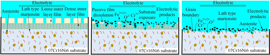
Schematic diagram of the electrochemical dissolution of 07Cr16Ni6 alloy in NaNO3 solution.
5 Conclusions
In this paper, the electrochemical dissolution behavior and surface passive film of the 07Cr16Ni6 alloy in NaNO3 solution were comprehensively studied. Firstly, the phase composition of the 07Cr16Ni6 alloy was characterized by XRD. Secondly, electrochemical measurements of the 07Cr16Ni6 alloy were performed to investigate the characteristics of the passive film and anodic dissolution behavior. The composition and structure of the passive film were obtained via XPS and EIS. Furthermore, the current efficiency of 07Cr16Ni6 alloys was measured. Finally, the microstructures, surface roughnesses, and constituents of the machined surface were examined via SEM, confocal laser scanning microscopy, and EDX. The conclusions can be summarized as follows:
(1) The potentiodynamic polarization, electrolyte conductivity, and EOCP curves show that the 07Cr16Ni6 alloy exhibits typical passive and transpassive behaviors, and its breakdown potential is about 1.272 V.
(2) The XPS and EIS analysis results show that the passive film of the 07Cr16Ni6 alloy in NaNO3 solution mainly consists of Fe3O4, α-Fe2O3, γ-Fe2O3, Cr2O3, NiO, SiO, and SiO2, and its structure is composed of a dense inner-layer film and a loose outer-layer film. A schematic model of the interface structure of the 07Cr16Ni6 alloy in NaNO3 solution was proposed.
(3) The current efficiency of the 07Cr16Ni6 alloy in NaNO3 solution first rises gently, and it then rises steeply once the current density exceeds about 26 A cm−2; subsequently, it remains stable when the current density is greater than about 45 A cm−2.
(4) 07Cr16Ni6 alloy exhibits different surface microstructures at low and high current densities. As the current density is increased, the number of blocky bulges on the machined surface decreases, improving the surface quality. Under low current density, the machined surface exhibits a morphology with loose, blocky bulges; conversely, there is a lath-type martensite morphology at high current density. Finally, a model of electrochemical dissolution of the 07Cr16Ni6 alloy in NaNO3 solution was established.
Funding
This work was supported by the National Natural Science Foundation of China (No. 52205468), Natural Science Foundation of Zhejiang Province (No. LD22E050001).
CRediT authorship contribution statement
Jingtao Wang: Conceptualization, Data curation, Methodology, Writing – original draft, Funding acquisition, Resources. Zhaoyang Zhang: Funding acquisition, Resources, Writing – review & editing. Wei Xue: Formal analysis, Funding acquisition, Resources, Writing – review & editing. Hao Zhu: Formal analysis, Resources, Writing – review & editing. Kun Xu: Formal analysis, Resources, Writing – review & editing. Yang Liu: Funding acquisition, Resources, Writing – review & editing.
Declaration of competing interest
The authors declare that they have no known competing financial interests or personal relationships that could have appeared to influence the work reported in this paper.
References
- Corrosion behavior biocompatibility of additively manufactured 316 L stainless steel in a physiological environment: the effect of citrate ions. Addit. Manuf. 2020;34:101237
- [Google Scholar]
- Improvement on surface quality of 316L stainless steel fabricated by laser powder bed fusion via electrochemical polishing in NaNO3 solution. J. Manuf. Process. 2022;83:325-338.
- [Google Scholar]
- Anodic dissolution mechanism of TA15 titanium alloy during counter-rotating electrochemical machining. Sci. China. Technol. Sci.. 2022;65:1253-1262.
- [Google Scholar]
- Liu X.B., Influence of surface modifications on pitting corrosion behavior of nickel-base alloy 718. Part 2: effect of aging treatment. Corros. Sci. 2014;78:151-161.
- [Google Scholar]
- Anodic electrochemical behaviors of Inconel 718 and Rene 65 alloys in NaNO3 solution. J. Mater. Res. Technol.. 2023;26:7312-7328.
- [Google Scholar]
- Refined thermal stability of Cr/Sc multilayers with Si(Be) barrier layers. Appl. Surf. Sci.. 2023;611:155743
- [Google Scholar]
- The electrochemical behaviour of stainless steel AISI 304 in alkaline solutions with different pH in the presence of chlorides. Electrochim. Acta. 2011;56(14):5280-5289.
- [Google Scholar]
- Novel observation of dominant role of strain rate over strain during pre-straining on corrosion behaviour of 304L austenitic stainless steel. Mater. Chem. Phys.. 2022;277:125522
- [Google Scholar]
- Corrosion behavior of additively manufactured 316L stainless steel in acidic media. Materialia. 2018;2(7)
- [CrossRef] [Google Scholar]
- Micropatterning of Ni-based metallic glass by pulsed wire electrochemical micro machining. Intermetallics. 2017;81:16-25.
- [Google Scholar]
- Electrochemical machining and allied processes: a comprehensive review. J. Solid. State. Electrochem. 2023
- [CrossRef] [Google Scholar]
- Characterization of high-temperature oxide films on stainless steels by electrochemical-impedance spectroscopy. Oxid. Met.. 1998;50:431-455.
- [Google Scholar]
- Comprehending the role of individual microstructural features on electrochemical response and passive film behaviour in type 304 austenitic stainless steel. Corros. Sci. 2021;180:109187
- [Google Scholar]
- Corrosion and interfacial contact resistance behavior of electrochemically nitrided 316L SS bipolar plates for proton exchange membrane fuel cells. Energy 2017
- [CrossRef] [Google Scholar]
- Electrochemical study of the dissolution of oxide films grown on type 316L stainless steel in molten fluoride salt. Corros. Sci. 2021;186:109457
- [Google Scholar]
- Structure and microstructure evolution of a ternary Fe–Cr–Ni alloy akin to super martensitic stainless steel. Mater. Des.. 2013;50:392-398.
- [Google Scholar]
- Electrochemical dissolution behavior of phosphorus and boron doped Inconel 718 alloy in NaNO3 solution. J. Alloys. Compd.. 2023;94:169140
- [Google Scholar]
- Ultra-high strength martensitic 420 stainless steel with high ductility. Addit. Manuf. 2019;29:100803
- [Google Scholar]
- Electrochemical and spectroscopic study on the corrosion of Ti–5Al and Ti–5Al–5Cu in chloride solutions. Metals and Materials International. 2019;25:1511-1520.
- [Google Scholar]
- Degradation effect of carbonation on electrochemical behavior of 2304 duplex stainless steel in simulated concrete pore solutions. Corros. Sci. 2020;177:109006
- [Google Scholar]
- The electrochemical dissolution characteristics of Inconel 718 nickel base super alloy in the condition of electrochemical machining. Int. J. Electrochem. Sci.. 2018;13:1115-1119.
- [Google Scholar]
- Performance analysis of electrochemical micro machining of titanium (Ti-6Al-4V) alloy under different electrolytes concentrations. Metals. 2021;11(2):247.
- [Google Scholar]
- A new maraging stainless steel with excellent strength–toughness–corrosion synergy. Materials. 2017;10:1293.
- [Google Scholar]
- Electrochemical dissolution behavior of S-04 high-strength stainless steel in NaNO3 aqueous solution. J. Appl. Electrochem. 2020;50:1149-1163.
- [Google Scholar]
- Anodic dissolution characteristics of Inconel 718 in C6H5K3O7 and NaNO3 solutions by pulse electrochemical machining. Corros. Sci. 2021;183:109335
- [Google Scholar]
- Dependency of the pulsed electrochemical machining characteristics of Inconel 718 in NaNO3 solution on the pulse current. Sci. China. Technol. Sci.. 2022;65:2485-2502.
- [Google Scholar]
- Improving the profile accuracy and surface quality of blisk by electrochemical machining with a micro inter-electrode gap. Chin. J. Aeronaut.. 2023;36:523-537.
- [Google Scholar]
- Investigation of the electrochemical dissolution behavior of Inconel 718 and 304 stainless steel at low current density in NaNO3 solution. Electrochim. Acta. 2015;156:301-307.
- [Google Scholar]
- Assessment of candidate molten salt coolants for the advanced high temperature reactor (AHTR) ORNL/TM 2006
- [Google Scholar]
- Surface characterization and corrosion behavior of a novel gold-imitation copper alloy with high tarnish resistance in salt spray environment. Corros. Sci. 2013;76:42-51.
- [Google Scholar]
- Electrochemical machining of complex components of aeroengines: developments, trends, and technological advances. Chin. J. Aeronaut.. 2021;34(2):28-53.
- [Google Scholar]
- Study of the influence of the preparation method on the electrochemical dissolution behavior of Inconel 718. J. Appl. Electrochem. 2022;52:1149-1162.
- [Google Scholar]


