

Translate this page into:
Fabrication of magnesium bentonite hollow fibre ceramic membrane for oil-water separation
⁎Corresponding author. hafiz@petroleum.utm.my (Mohd Hafiz Dzarfan Othman)
-
Received: ,
Accepted: ,
This article was originally published by Elsevier and was migrated to Scientific Scholar after the change of Publisher.
Peer review under responsibility of King Saud University.
Abstract
Abstract
In this study, low-cost magnesium bentonite (MB) was used for the fabrication of bentonite hollow fibre (BHF) membrane with high pure water flux. MB powder was initially characterized by X-ray diffraction (XRD), X-ray fluorescence (XRF), particle size distribution (PSD) analyser, Brunnauer -Emmett- Teller (BET) method, and field emission scanning electron microscope (FESEM). The BHF membrane obtained was then fabricated through dope suspension mixing, phase inversion and sintering process. The dope suspension was prepared by mixing MB, dispersant, polymer binder, and solvent using a planetary ball mill. While the spinning process was carried out at the extrusion rate of 8 mL/min, a fluid bore rate of 10 mL/min and air gap of 5 cm, and this was followed by sintering operation at 950 °C, 1000 °C, 1050 °C, and 1100 °C. The resulting BHF membrane was characterized by scanning electron microscopy (SEM) and XRD; the porosity test, water flux and oil rejection were also examined. The SEM surface morphology of BHF at sintering temperature of 950 °C showed spongy-like and nested macrovoids structure; the porosity was 49.09% with a mean pore size of 3.9 µm. The performance test on the bentonite-based hollow fibre membrane showed that the membrane prepared at 20 wt% and sintering temperature of 1000 °C, which induced high and stable permeate water flux and oil rejection of BHFC membrane were 544 L/m2 h and 97%, respectively. The results have shown that the presence of magnesium in bentonite can enhance and promote the needed support material for the fabrication of hollow fibre ceramic membrane.
Keywords
Magnesium bentonite
Phase inversion
Sintering technique
Hollow fibre
Oil-water separation

1 Introduction
The use of organic membrane such as polymer membrane has been commercially available for the separation and filtration processes of wastewater. The polymeric membrane tends to have challenges associated with its durability, chemical and thermal stability as compared with the inorganic membrane, such as a ceramic membrane (Dong et al., 2012). In contrast, ceramic membrane possesses more advantages over the polymeric membrane in terms of the comparatively thin pore size distribution and higher porosity, resulting in permeate-selectivity and high flux, higher mechanical strength allows good resistance to pressure. Its chemical stability promotes longevity of the membrane and excellent hydrophilicity attributes to lower membrane fouling, and ceramic materials are not too expensive (Hofs et al., 2011), thus the utter need to develop low-cost ceramic membrane.
Bentonite as a low-cost ceramic material has a characteristic of swelling when in- contact with solvent and can exchange ions with a vast range of metals and other minerals, low firing temperature and also showed good thixotropy (Jackson, 2014). For instance, the aluminium phyllosilicate of bentonite contains aluminium ion in the octahedral position, which can be easily displaced with cations of lower valences such as magnesium, calcium or sodium. On the other hand, bentonite with magnesium as cation at the octahedral position can be better off to replace calcium and sodium because of its less solvent adsorption and its insignificance in separation into a separate sheet of alumina-silicate (Jackson, 2014). These low-cost ceramic materials over the years have metamorphosed into various areas of application because of overwhelming excellent thermal, chemical and microbiological stabilities, long time operability, high hydrophilicity and low hydrophobicity (Petrović et al., 2014).
The use of bentonite-based ceramic membrane has gained much interest from many researchers (Bouazizi et al., 2017; Chihi et al., 2019; Del Colle et al., 2011; Eom et al., 2014; Eom et al., 2015; Fang et al., 2013; Harabi et al., 2014; Jana et al., 2010; Li et al., 2017; Nandi et al., 2008; Sahnoun and Baklouti, 2013; Yeom et al., 2016; Kurada et al., 2020) and offers overwhelming performance over an extended service period which gives rise into a lower operating cost. Eom et al. (2015), fabricated microfiltration (MF) ceramic membranes from a silicate and clay mineral textures of diatomite, kaolin, bentonite, talc, sodium borate, barium carbonate for oily wastewater; with a mean pore size obtained at 0.4 µm. The performance showed that water flux and oil rejection were 0.09 L/m2h.bar, and 92.9% respectively. In a similar work, Bakalár et al., 2013 studied the influence of an internal configuration of MF membrane of bentonite (montmorillonite) suspensions with supported αAl2O3 and ZrO2 in the fabrication of tubular ceramic membrane microfilter, and the results revealed a mean pore of 0.120 µm and water flux of 160 L/m2h.bar were obtained. In contrast, Bouazizi et al., 2016 carried out an elaborated work on the application of flat disk MF membrane for industrial wastewater treatment from natural Moroccan bentonite clay using uniaxial pressing to fabricate a flat sheet membrane and sintering method. The elaborated findings indicated that wastewater removal efficiency was 99%, and water flux was also 520 L/m2h.bar. Chihi et al., 2019 examined the use of low-cost Tunisian bentonite clay for wastewater treatment from tubular ceramic MF membrane while applying the extrusion and sintering technique for the fabrication. The water flux was obtained at 525 L/m2h.bar and mean pore size of 1.7 µm was observed. Eom et al. (2014), investigated the combined kaolin, talc and bentonite mixtures for the MF ceramic membrane in the treatment of oily wastewater emulsion, where the oil rejection was 96.7%, and the flux was 226.8 L/m2h.bar.
The limitation on the application of a tubular, flat and disc-shaped membrane is the nature of their low surface area-volume ratios, and the thick membrane walls, which makes them have the disadvantage of low production in an industrial application (Bukhari et al., 2017; Govindan et al., 2019; Yuanfa et al., 2017; Mohammadi et al., 2018; Park and Chung, 2017; Wang and Wu, 2018). The retention capabilities usually lost as a result of low surface area per unit volume of the membrane, which is more pronounced in the flat membrane as compared to other configurations during long-time operation as expected, as a result of specific affinity rather than steric factor (Achiou et al., 2016a, 2016b; Elomari et al., 2016; Issaoui et al., 2016, Bouazizi et al., 2017; Criscuoli, 2019; El Qacimi et al., 2019). Meanwhile, the fabrication of bentonite hollow fibre membrane is yet to be explored as most of the researchers from earlier discussed studies mainly developed flat sheet and tubular membrane modules from this low-cost material using uniaxial pressing and extrusion techniques. Fabrication of hollow fibre ceramic membrane possesses more advantages such as higher surface area, higher water flux, lower pressure drops across the module, and easy backwashing (Hubadillah et al., 2018). To the best of our knowledge, there is no study that has successfully used bentonite as a sole starting material for the fabrication of hollow fibre ceramic membrane.
This study aims to develop the ceramic hollow fiber membrane derived from magnesium bentonite. The characterization of magnesium bentonite and properties such as the water flux and water permeability of the membrane were systematically investigated. The oily/water separation performance of magnesium bentonite ceramic hollow fiber membrane was also determined in the final part of this study.
2 Experimental
2.1 Materials and methods
Bentonite powder was purchased as a commercial starting material from Aladdin Industrial Corporation Shanghai, China and other additives such as polyethylene glycol 30- dipolyhydroxystreate (Arlacel P135, CRODA), N-methyl-2-pyrrolidone (NMP) (HPLC grade, Rathbone), polyethersulfone (PESf) (Radel A-300, Ameco Performance) were used as a dispersant, solvent, and a binder respectively. All materials were used as received.
2.2 Preparation of bentonite suspensions
The bentonite content loading in the dope suspension was varied at 18 wt% and 20 wt% to obtain dope suspension viscosity. The choice of 18 wt% and 20 wt% bentonite loading were considered because at loading below 18 wt%; the dope suspension becomes less viscous. Whereas at above 20 wt% the dope becomes highly viscous to be spun. This can be attributed to the characteristic behaviour of swelling when in-contact with solvent. Arlacel P135 (1% wt) was weighed and dissolved in NMP solvent (74 wt% and 76% wt). After oven-drying for 12 h, the dried bentonite powder was added slowly into the mixture of Arlacel P135 and NMP and followed by mechanically stirring. NQM-4 planetary ball mill at 194 rpm for 48 h was used to mill the dope suspension to ensure proper distribution of bentonite powder. The PESf (5 wt%) was added to the mixture after 48 h to achieve proper dispersion and binding of the mixture for another 48 h. The prepared bentonite dope was degassed on a gentle stirring for 30 min to ensure that air bubble trapped is purged from the dope.
2.3 Fabrication of bentonite ceramic hollow fibre membrane
After degassing was complete, the prepared bentonite dope suspension was loaded into 200 mL stainless steel syringes. The dope suspension and the deionised water (the internal coagulant from the bore fluid machine) were extruded by the syringe pump (PHD2000, Harvard Apparatus) via the spinneret at a constant flow rate of 10 mL/min at room temperature and an air gap of 5 cm. The membrane precursor was then immersed in water for 12 h to ensure a complete phase inversion, followed by thorough washing with water. Fig. 1, illustrated the spinning process of the bentonite hollow fibre ceramic membrane. Furthermore, the precursor fibres were cut into 20 cm in length and dried at room temperature for 24 h. The sintering process was carried out using a tubular furnace (Model: XL-1700, Magna value) with the precondition to allow the initial thermal decomposition of organic solvent and other additives. Then, the sintering temperature was programmed to 650 °C at the rate of 3 °C/min for a period of 2 h and followed by a heating rate of 5 °C/min for another period of 5 h to the targeted temperature. Four different targeted temperatures of 950 °C, 1000 °C, 1050 °C, and 1100 °C were used in this work. Then a gradual drop in the temperature was set from the targeted temperature to room temperature at the rate of 5 °C/min.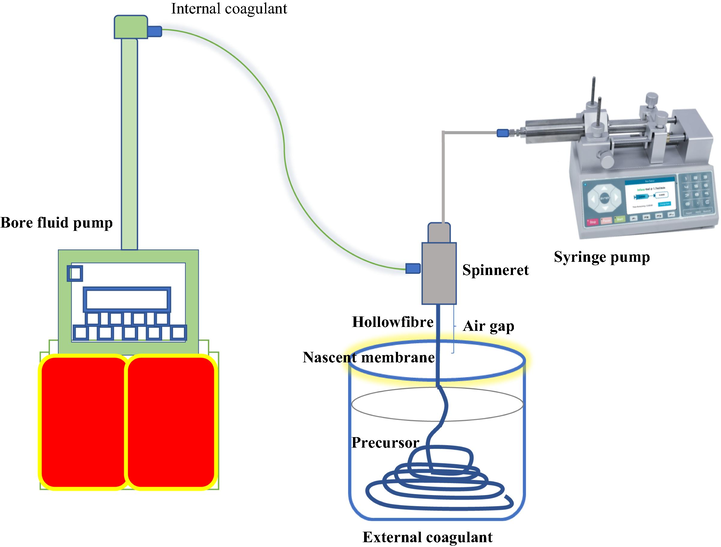
Schematic representation of spinning process of bentonite hollow fibre membrane.
2.4 Characterization of bentonite powder
Bentonite powder surface structure was investigated by field emission scanning electron microscopy (FESEM). The structures of bentonite powder were observed using FESEM at 2 kV with a varied magnification range from 10,000 to 70,000 on HITACHI: SU8020. The particle size and distribution of porous particles are one of the important characterizations in establishing the quality and performance of porous particles, which may influence some properties such as, permeability, mechanical, compaction and thixotropy of material. Bentonite particle size distribution was performed using a Malvern instrument (MAL 1098100) zeta sizer ver.7.11 using water as a dispersant while it was conditioned at an ambient temperature of 25 °C for 70 s at a count rate of 136 kcps. Zeta potential analysis was used to evaluate the surface potential or charges of a material. The zeta potential potential was evaluated at pH 7 and measured using a zetasizer (Malvern Zetasizer Version 7.11, United Kingdom). While the XRF was used to determine the chemical composition of bentonite powder and the X-ray diffraction was used to measure bentonite powder crystalline microstructure and its transformation phase behaviour. XRD patterns works based on diffraction angle, which ranges from 0° to 100° 2θ with a step size of 0.02° and step time of 60 s, operated at 40 kV and 30 mA with a fixed 2/3° incident slit on the X-ray diffractometer (D/max B 12 KW Rigaku @ D5000 Siemens with an attachment of ASC robot- reflection) via Cu Kα radiation, and Ni filter with a wavelength of 1.5406 nm. However, the BET was used to establish the specific surface area of bentonite powder on N2 adsorption/desorption isotherms (with a relative pressure range from 0 to 0.99) of which the classic relative pressure ranges from (P/Po) 0.05–0.30. While the particle size distribution such as total pore volume, surface area and average pore diameter of the bentonite powder was calculated based on the Gurvitch method.
2.5 Characterization of bentonite ceramic hollow fibre membrane
BHF membrane surface structure was examined using a scanning electron microscopy (SEM) with a varied magnification range from 100 to 8000 on HITACHI: TM3000. SEM examines the cross-section as well as the macrostructure surface of the membrane. In order to study the effect of loading and sintering temperature on the morphology of BHF membrane, the overall morphology and cross-section of bentonite membrane (18 wt% and 20 wt% loadings) at sintered at 950 °C, 1000 °C, 1050 °C and 1100 °C was observed by SEM. The porosity and pore size distribution were investigated on the BHF membrane at different temperature using mercury extrusion porosimetry (MEP, Autopore IV, micrometric, USA). A piece from BHF membrane was placed unto 5 cc penetrator sample holder (micrometric, USA), which was then pressurized from 38.6 to 4,200,000 Mbar for the mercury intrusion. Eq. (1) was used to calculate the relationship between and the diameter of the capillary of the penetrometer.
2.6 Performance evaluation
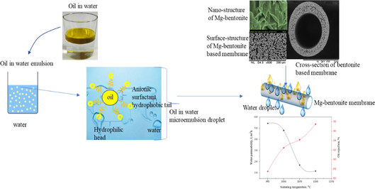
Water flux was conducted via a cross-flow filtration step up. The water flux, denoted by Jw (L/ h.m2) at 1 bar. The pure water flux was determined using Eq. (2). The oil rejection performance evaluation of bentonite-based membrane was carried out using prepared oily water concentration at 0.5 g/L, 1 g/L, and 1.5 g/L. The oil-water emulsion was prepared using edible oil (Carotino red palm oil) and sodium dodecyl sulfate was added as an anionic surfactant at the ratio of 1:5 for each of the concentration. The oil rejection tests were conducted at a room temperature by using microfiltration set-up for 90 min under the pressure of 3.5 bar, and Eq. (5) was applied to calculate the oil rejection. Oil feed at different absorbance concentrations in the solution was measured using UV–vis spectrophotometer (DR500, Hach) at the wavelength of 272 nm of oil in water before and after filtration.
The oil rejection, R was determined using Equation (5).
3 Results and discussions
3.1 Properties of bentonite powder
FESEM images of bentonite powder indicated in Fig. 2 provides topographical information with a clear and less distorted images at variant magnifications between 10, 000 and 70, 000 resolutions, the images revealed flake-like (Fig. 2a and 2c) structures of abundant silicates interlayers with a compacted interlayer order of heterogeneous surface morphology (Olalekan et al., 2010; Pawar et al., 2016). It was also clearly observed in Fig. 2b, and Fig. 2d, a lamellar curly surface of bentonite (Yi et al., 2014; Xiong et al., 2019). Several lamellar-flake particles with diameters more than 0.5 μm were observed as indicated in Fig. 2a–d. In addition, several interlayer cation radii were compared and found to increase in the following order: Mg2+ < Ca2+ < Li+ < Na+< K+. The interlayer cations of bentonite were determined as Mg2+ and Ca2+ (Table 1). Due to small radius and high hydration energy of Mg2+, more water molecules could easily be adsorbed on the surface of bentonite particles. The electrostatic attraction of particle lamellae could be overcome by repulsive forces, causing swelling and flakes formation as bentonite sheets (Callaghan and Ottewill, 1974), this is presented in Fig. 2.
FESEM of bentonite powder images at different magnifications (a–d).
Bentonite
SiO2
MgO
CaO
Al2O3
Fe2O3
K2O
P2O5
TiO2
%
55.8
20.5
3.7
1.6
1.1
0.5
0.3
0.1
The particle size distribution of bentonite, as shown in Fig. 3. 0.3% of the particles size present a diameter <0.255 μm, while 0.2% presents >0.825 μm particle size, and with an average particle size of 0.531 μm. Hence, with the actual size distribution within the range of 0.342–0.825 μm dominated; this accounted for 99.5% of the cumulative volume.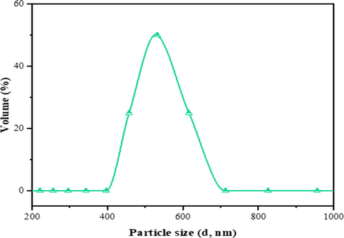
Particle size distribution of bentonite powder.
This result indicates that the bentonite powder is composed of small aggregations and monodispersed particles (0.531 µm), which is consistent with reported works (Balnois et al., 2003; Nicolai and Cocard, 2000). The latter was mainly related to the swelling capacity of smectite, which depended on the interlayer cation radius and cationic hydration energy (Anderson et al., 2010; Laird, 1996). This concept further showed the significance of interlayer cation exchange of hydration variances flanked by the bulk aqueous phase and the smectite interlayer phase. Hence, the assertion is that small aggregates and monodisperses such as the Mg2+, Ca2+, and Na+ in the bentonite would become more and strongly attracted by the surface. That is cation exchange occurs because less strongly held ions wander too far from the surface, giving chances for more strongly bounds to take their places near charged sites (Teppen and Miller, 2006). Thus, the small aggregations and monodispersions favour clay-cation interactions, as indicated in Fig. 3 and Table 1.
Chemical composition of bentonite powder by XRF as indicated in Table 1, the results show that bentonite powder contained a large proportion of silica with other metal oxides formed the remaining compositions such as magnesia, calcium oxide, alumina, iron, and other components in trace amount. The presence of highly rich silica and magnesia attested to the fact that bentonite powder with other additives can be used for the fabrication of hollow fiber ceramic membrane. Both the silica and magnesia account for over 70% of the composition. Besides, Bouazizi et al. (2016) findings showed that silica and alumina were above 70% in bentonite composition with less than 2% magnesia. While Chihi et al. (2019) reported above 80% of silica and alumina with less than 3% magnesia. The disparities can be explained further with respect to interlayer cation exchange of hydration variances.
The adsorption–desorption isotherm obtained for bentonite powder was of type V with H3 hysteresis loop, according to the IUPAC classification, as shown in Fig. 4. The hysteresis loop confirmed the bentonite particles possess slit-shaped (flakes) pores at low pressure. This indicates that the bentonite powder does have rigid interlayer during the adsorption process. Therefore, the capillary adsorption (condensation) of the bentonite powder remained filled to the larger pore radius and the equilibrium was established until the vapour pressure of the smaller pore radius was reached gain (Callaghan and Ottewill, 1974). The significance of this is that the capillary adsorption tends to minimize the effect of sintering at a higher temperature. More so, the three layers (2:1) of the platelets are held together by the interlayer cations, which compensate for the negative charge of faces of the layer. The shape of the isotherms exhibits a hysteresis, which reveals the presence of mesopores. The uniform distribution of points on the graph (Fig. 4) is an indication of desorption, and the dispersive points on the plot are isotherm adsorption. The mode radius pore of the bentonite powder lies in the mesoporous range (Table 2). In contrast, the average radius of the sample is in the microporous range (Fig. 3). This revealed that the bentonite sample possesses a wide range of pore size distribution. In addition, the zeta potential of bentonite was evaluated to investigate the surface energy. The zeta potential analysis (Fig. 5) showed a negative charge (−12.4 mV) attained at pH 7 indicate that the charge at −12.4 mV would to increase the affinity of the hollow fibre ceramic to attract and adsorb the free moving positive ions in the feed solution. However, the negatively charged surface can impact the driving force for the electrostatic interaction with the positively charged adsorbate (Adam et al., 2020).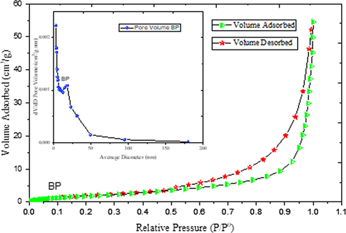
N2 adsorption–desorption isotherm, inset BJH pore size distribution derived from the N2 sorption isotherms for bentonite powder.
Parameter, units
Results
Test methods
Bentonite
BET specific surface area (m2/g)
8.37
ASTM D3663-03
BJH average pore diameter, µm
0.035
ASTM D4222-03
BET pore specific volume (cm3/g)
0.063
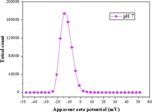
Zeta potential of bentonite powder at pH 7.
Furthermore, the average pore diameter, specific surface area and pore volume are quantitatively indicated in Table 2, the bentonite powder specific surface area and average pore diameter were 8.37 m2/g and 0.035 μm from the B.E.T analysis, respectively. The B.J.H method was used to determine the pore volume as 0.063 cm3/g. The t- plot method was also used to find the mesopores specific area and the micropores volume, which are 36.656 m2/g and −0.014 cm3/g, respectively (Bouazizi et al., 2016).
3.2 Rheological behaviour of dope suspension
The viscosity of bentonite suspensions at the relative shear rates ranges from 0.5 to 100 s−1 as contained in 18 wt% and 20 wt% in the dope suspension. Fig. 6, shows a tremendous increase in the viscosity with increase in bentonite loadings. Also, the trends can be attributed to the shear-thinning behaviour as the shear rates increase with a decline in the bentonite viscosity with the two loadings. Similar viscosity behaviours can be noted from the works of (Hubadillah et al., 2018; Kingsbury and Li, 2009). Furthermore, the effect of bentonite loading plays a significant role in the macrovoids structure on the membrane formation, just like other air gaps and extrusion rates influence membrane macrovoids structure. The macrovoids structure diminishes as the bentonite loading increases these can be confirmed on the SEM images (Fig. 7). It was found that the viscosity threshold was attained at 594.2 cP for 20 wt% and 322.7 cP for 18 wt% at 30 s−1.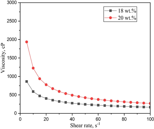
Viscosity of ceramic suspension at different bentonite content.
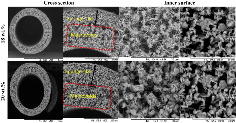
SEM images of bentonite hollow fiber (BHF) membrane prepared at different bentonite loadings.
3.3 Effect of bentonite content on membrane morphology
Fig. 6 shows the surface morphological view of the two membranes BHF18 and BHF20. The figure depicts the cross-section and inner surface view of the membranes that were sintered at 950 °C. As it can be seen, the BHF with the loading of 18 wt% happens to possess an asymmetric structure of nested macrovoids which originates from the inner portion of the membrane surface and also occupies about 70% of the membrane structure while the remaining 30% of the membrane thickness was occupied by sponge-like layer.
This is in line with the previous studies by Kingsbury and Li (2009) that the higher viscosity of the ceramic suspension lowers the formation of macrovoids in the hollow fibre structure. Therefore, macrovoids will tend to be entirely diminished if the ceramic dope suspension viscosity reached a certain threshold as reported in the works of (Husain and Koros, 2009; Othman et al., 2010). In this case, the asymmetric feature for macrovoids structure tend to disappear due to low dope suspension viscosity of BHF20, as shown in Fig. 7. The BHF20 with the loading of 20 wt% also possessed an asymmetric structure of nested macrovoids which originates from the inner portion of the membrane surface and also occupies about 50% of the membrane macrovoids structure while the remaining 50% of the membrane thickness was occupied by sponge-like layer. The inner surfaces of the BHF18 and BHF20 revealed a nested macrovoids structure. This can be attributed to an interlayer structure of bentonite, as indicated in Fig. 2.
3.4 Effect of sintering temperature on membrane properties
Fig. 8 shows the surface morphological view of the four different sintered membranes, BHF18 and BHF20. The surface morphology depicted from the cross-section and inner surface of membranes were sintered at 950 °C, 1000 °C, 1050 °C, and 1100 °C. As can be seen in Fig. 8, the BHF with the loading of 18 wt% showed that as the sintering temperature increases, the asymmetry structure of sponge-like voids tends to become dense and compact; meanwhile, the nested macrovoids seem to be a standstill and become partly and gradually melted with an increase in sintering temperature. It can also be seen that the membrane sintered at 950 °C has the most porous structure as compared to the one sintered at 1100 °C, which possess a less dense structure. Therefore, with a gradual increase in sintering temperature from 950 °C to 1100 °C, the pore size of the sponge-like voids in the cross-sectional view of the membranes tend to reduce, and the pore size becomes isolated on the surface of the membrane. On the further increase in sintered temperature 1050–1100 °C, the nested macrovoids region becomes also melted and the pores become densely isolated. While both the external and internal diameters decrease from 1.10 mm to 0.991 and 0.746 mm to 0.667 mm, respectively as the sintering temperature also increases from 950 °C to 1100 °C. Similarly, the same can be explained by the sintering temperature effect on the BHF20. The cross-section showed an increase in sintering temperature from 950 °C to 1100 °C. At 1050 °C and 1100 °C many closed pores were attained, the structure became dense and compacted at 1100 °C. This structural changes can be attributed to bentonite particles transformation through neck formation, growth, and final fusion (Abdullah et al., 2016; Hubadillah et al., 2018; Kurada et al., 2020).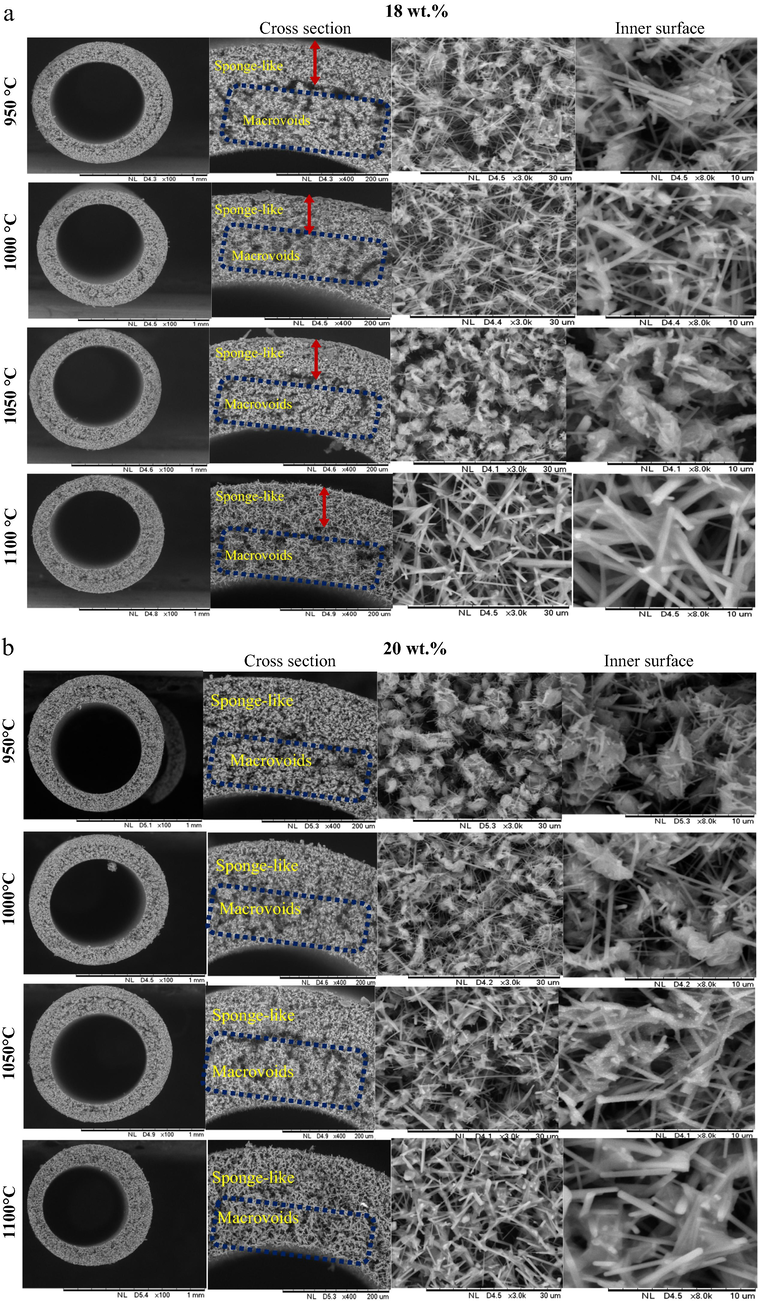
SEM images of bentonite hollow fiber ceramic membrane (BHF) prepared at different sintering temperatures and bentonite loadings (a) 18 wt%, (b) 20 wt%.
The changes observed in the porosity (Fig. 9) with the increasing sintering temperature was very clear and apparent. Different particle sizes have affected the pore size distribution of the membrane. The porosity value decreased from 49.09% at the initial sintering temperature of 950 °C to 27.22% at the final sintering temperature of 1100 °C. This can, therefore, be attributed to the formation of small pores, which conversed with Fig. 7 at the same sintering temperature. While the porosity values also decreased from 43.56% to 39.74% for the bentonite hollow fibre membranes sintered at 1000 °C and 1050 °C respectively.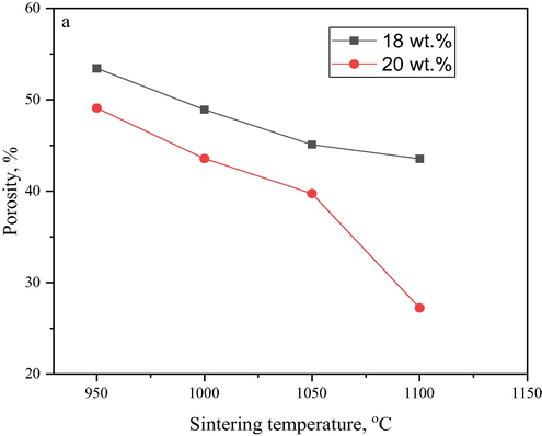
Porosity bentonite hollow fibre ceramic at different contents.
The X-RD pattern in Fig. 10 represents primarily, the raw bentonite powder and fabricated membranes at different sintering temperatures. The characterization peaks and planes were indicative of the main involvement of interlayers between tetrahedral and octahedral (2:1) of the enstatite mineral family and confirm the presence of magnesium montmorillonite (bentonite) as shown in Table 1. Hence, the characteristic peaks and planes (as indicated in Fig. 10) for MgM are as follows: 19.5° (2 0 0), 29.3° (4 0 0), and 60.9° (2 2 0), respectively (Ingole et al., 2017). All the peaks pattern shows a continuous amorphous phase and the presence of MgM. The presence of MgM was confirmed with a series of intense peaks as reported by Bouazizi et al. (2016). Other phases present were in lower quantities such as quartz, feldspar, illite and calcite in the bentonite powder and membrane pristine. There were still noticeable crystalline peaks and planes, and a shift to the right, which was defined as 25.8° (2 2 1), 26.29° (4 2 0), 26.92° (6 1 0), 28.189° (3 2 1), 30.361° (4 2 1) and 31.05° (1 3 1). Also, other phases such as the carbonates, feldspars, and cristobalite appeared due to the thermal treatment and disappeared at an increased temperature and later shift in phase, which were considered as impurities.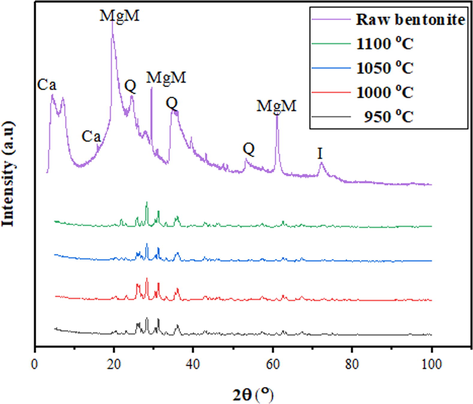
XRD analysis for bentonite powder and bentonite hollow fibre membrane at sintering temperature of 950 °C, 1000 °C, 1050 °C and 1100 °C. Where MgM: Magnesium montmorillonite, Ca: Calcite, Q: Quartz, I: Illite.
Fig. 11 revealed a significant peak above 10 µm, which has been attributed to the macro voids where another modal peak occurred at lower pore size region of 4.35 µm which represents the sponge-like pore as presented in SEM images (Fig. 8). The porosity declined at sintering temperature of 1050 °C and 1100 °C due to the pristine pores densification (Bouazizi et al., 2017). These behaviours can also be supported with the lower water flux and partial melting of the nested-finger structure of BHF, as indicated in Fig. 11. Largely, the porosity depends on the pore size of the membrane voids. However, the results from MIP showed the pore size distribution of the bentonite membrane at 950 °C was characterized by the macrovoids structures at 4.77 µm and a smaller peak less than 9.7 µm represents sponge-like structure as stated by Hubadillah et al., 2016. While bentonite membrane sintered at 1000 °C shows a similar behaviour with pore size range from 4.40 µm to 9.7 µm as revealed in Fig. 8 representing the less of macrovoids and more sponge-like structure (Fig. 10). However, as the sintering temperature increases from 1050 °C to 1100 °C, both sintered membranes indicated only one distinctive peak at 4.35 µm and 4.30 µm but showed less macrovoids and sponges-like voids due to the membrane densification of the pores.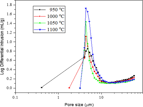
Pore size distribution of bentonite hollow fiber membrane at different sintering temperatures.
3.5 Pure water flux of membrane
Permeation performance of bentonite hollow fibre membrane was examined based on pure water flux test. The results revealed that the pure water flux largely relied on the pore size and porosity. Fig. 12 illustrates the water flux of the bentonite hollow fibre membranes prepared at different sintering temperatures. Two trends were observed, where the pure water flux declined with permeation time, and the flux decreased when the sintering temperature increased from 950 °C to 1100 °C. Fig. 12a and b revealed a similar decline in water flux for the three sintering temperatures at 950 °C, 1000 °C, and 1050 °C within 40 min permeation. This can be attributed to the instability in the flux, although the fluxes were quite high. The significance of the unstable flux can be due to its highly porous structures as there are less water molecule resistance during the filtration process (Hubadillah et al., 2016). In addition, further decline was observed in all the four sintering temperatures between 40 min and 60 min. Therefore, the trend can be attributed to the saturation of the pores and increase in resistance as a result of interaction between the bentonite membrane and water molecule at the membrane surface. Hence, the water permeability of bentonite membrane at the transmembrane pressure of 1 bar showed a decline with the ascending order of sintering temperature of 950 °C (∼544 L/h.m2),> 1000 °C (∼481 L/h.m2) > 1050 °C (∼224 L/h.m2) > 1100 °C (∼25 L/h.m2). Ideally, the separation mechanism of the ceramic membrane is based on the pore size of the ceramic membrane. The results of water flux against permeation time, as shown in Fig. 12, the membrane sintered at 950 °C and prepared at 18 wt% bentonite loading possesses the highest flux due to its sponge-like structure. The structure became densified and melted at 1050 °C and 1100 °C; resulted in low flux during the permeation process. The behaviour was expected as the SEM displayed the morphological changes due to the heat treatment, which can be attributed to pore size, porosity, and tortuosity in accordance with the findings of Abdulhameed et al. (2017). Also, FESEM analysis provides the flaky nature of bentonite particles, and the voids formed between particles due to their irregular shapes (Abdulhameed et al., 2017).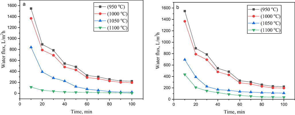
Variation of water permeate flux of support BHF sintered at 950 °C, 1000 °C, 1050 °C, and 1100 °C (a) at 18 wt% bentonite content, (b) at 20 wt% bentonite content.
3.6 Oil-water separation performance
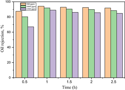
Fig. 13 shows the oil size distribution of the feed samples were characterized by particle size analyzer (PSA, Litesizer, 500). The oil size distribution in the emulsion indicates that some oil droplet evenly distributed with the diameter more than the bentonite membrane pore size (Fig. 10). This shows that the membrane pore size to a large extent would be able to reject the oil at the surface. Hydrophilicity is very desirable in oil-water separation as it is believed the hydrophilic surface will allow the water to penetrate the membrane surface due to water-induced molecular rearrangement such that the hydrophilic moieties locate at the interface while rejecting the oil molecules, as well as effectively mitigating membrane fouling. Fig. 14 illustrates the oil rejection performance of BHFM using prepared oil-water emulsion at 20 wt% bentonite content and 1000 °C sintering temperature based on the evaluation in Figs. 8 and 12. The permeate concentration of oil increased with increase in the feed concentration. The increase in oil concentration led to a gradual decrease in the rejection percentage at different rejection times. Initially, the oil rejection percentage decrease was observed when the oil concentration increased from 500 ppm to 1500 ppm with respect to the initial time of 30 min. After further increase in the rejection time, a similar trend was observed with an increase in the oil concentration. The rejection concentration was expected to increase with increasing time as the system was operated under cross-flow filtration step-up. More so, the pressure was kept at 3.5 bar, which was quite high. This can be attributed to the presence of high emulsified oil particles in the oily water, which builds up oil cakes on the membrane surface. With the increase in the viscosity of the feed solution, which subsequently lowers the flux performance by posing high water transport resistance on the membrane surface (Al-Alawy and Al-Musawi, 2013). The denser pore structure with lower porosity and pore size enhanced the sieving mechanism of the large oil particles, which were refrained from entering the smaller membrane pores and kept at the feed side (Hubadillah et al., 2017; Tai et al., 2019). It can be observed that the high oil rejection performance 97.2% was obtained at 500 ppm oil concentration, suggesting that BHFM can be an excellent alternative membrane for the oil-water separation.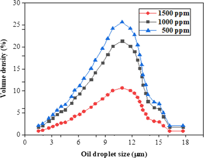
Oil droplet size of oil-water emulsion at different concentrations.
Oil rejection of bentonite hollow fibre ceramic membrane of feed concentrations.
Fig. 15, also illustrates the variation of the permeate flux and rejection as a function of sintering temperature for separating oil-water emulsion. It was revealed that the permeation decreased with increase in sintering temperatures of bentonite hollow fibre ceramic membrane. In addition, the densification of membrane pores, especially the outer-layer structure (sponge-like voids) as indicated in Fig. 7, revealed that higher sintering temperatures led to the formation of dense bentonite hollow fibre ceramic membrane and a decline in the permeation performance. Meanwhile, there was an increase in sintering temperatures in oil rejection. This can be due to the densified macro-voids, as shown in Fig. 9, and thus allows for the sieving mechanism towards the oil-water separation. It can be observed that oil rejection and best sintering temperature were attained at ∼97% and 1000 °C, respectively. This indicates that bentonite hollow fibre membrane can be effectively used for oil removal from the oily wastewater.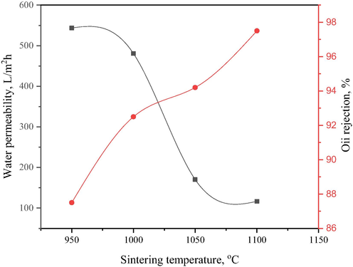
Variation of permeate flux and oil rejection with sintering temperature for bentonite hollow fibre ceramic membranes.
3.7 Comparison with other bentonite-based membranes
The oil rejection performance of bentonite hollow fibre ceramic membrane was evaluated and compared with other bentonite-based membranes, as indicated in Table 3. The results suggest that fabrication of bentonite-based ceramic membranes were based on the other configurations such as flat sheets and tubular as reported by Kurada et al. (2020), Chihi et al. (2019), Bouazizi et al. (2016), Vinoth Kumar et al. (2015) and Eom et al. (2014). The techniques such as uniaxial pressing and extrusion were used during the preparation of the membrane as compared with phase inversion technique. More so, the results revealed that the permeation system was operated at a lower pressure. It can be observed that bentonite at lower material loading possesses high oil rejection and as well as water flux at 1.5 g/L concentration of feed oil. Bentonite membrane possesses high efficiency with both the oil rejection and water flux, thus were better of as compared to other membranes with different configurations. Therefore, bentonite hollow fibre ceramic membrane promises a better alternative in terms of preparation technique, configuration and performance.
Membrane material
Preparation technique
Membrane configuration
Pressure, bar
Oil concentration, g/L
Permeate flux, L/m2h
Oil rejection, %
Reference
Bentonite
Phase inversion
Hollow fibre
3.5
1.5
543.7
97.2
This work
Bentonite
Casting by Phase inversion
Flat sheet
3.5
–
0.000011
–
Kurada et al., 2020
Bentonite clay (smectite)
Extrusion
Tubular
–
–
525
–
Chihi et al., 2019
Bentonite clay
Compaction
Flat disk
–
–
520
99
Bouazizi et al., 2016
Kaolin, bentonite, talc
Uniaxial pressing-compaction
Flat disk
1.01
10
226.8
96.7
Eom et al., 2014
Mixed clay
Extrusion
Tubular
0.69
100
85.0
99.98
(Vinoth Kumar et al., 2015)
Mixed clay
Compaction
Circular disk
1.65
50
75.9
96.97
Nandi et al., 2009
4 Conclusions
Magnesium bentonite hollow fibre ceramic membrane was successfully fabricated using a phase inversion technique and sintering. Bentonite powder was effectively characterized by XRD, XRF, PSA, BET, and FESEM. The chemical compositions from XRF showed that silica (SiO2) and Magnesia (MgO) were the most abundant materials in bentonite. The optimal sintering temperature condition of the HFC membrane was obtained at 950 °C. The SEM surface morphology of BHF at sintering temperature of 950 °C showed spongy-like and macrovoids structure; the porosity was 49.09% with a mean pore size of 3.9 µm. The water permeability and oil rejection of BHFC membrane were 544 L/m2 h and 97% respectively. However, the results confirm that the BHF could be used as an MF in the application of wastewater treatment. Hence, in future work, the surface functionalization of HFC will be done to improve the mechanical strength and reduce the fouling in the membrane.
Acknowledgements
The authors gratefully thank the financial support from the Ministry of Education Malaysia under the Higher Institution Centre of Excellence Scheme (Project no. R.J090301.7809.4J430) and Universiti Teknologi Malaysia under the Transdisciplinary Research University (TDR) (Project no. Q.J130000.3509.05G75) and Malaysia Research University Network (MRUN) Grant (Project no. RJ130000.7809.4L867). The authors would also like to thank the Research Management Centre, Universiti Teknologi Malaysia for technical support. The authors gratefully acknowledge the financial support from the Tertiary Education Trust Fund (TETFund), Nigeria.
Declaration of Competing Interest
The authors declare that they have no known competing for financial interests or personal relationships that could have appeared to influence the work reported in this paper.
References
- Fabrication and characterization of affordable hydrophobic ceramic hollow fibre membrane for contacting processes. J. Adv. Ceram. 2017
- [CrossRef] [Google Scholar]
- Preparation and characterization of dual layer thin layer lanthanum strontium cobalt ferrite /alumina hollow fiber membrane using dip-coating and brush-coating techniques. Sains Malaysiana 2016
- [Google Scholar]
- Impact of sintering temperature and pH of feed solution on adsorptive removal of ammonia from wastewater using clinoptilolite based hollow fibre ceramic membrane. J. Water Process Eng.. 2020;33:101063
- [CrossRef] [Google Scholar]
- Microfiltration membranes for separating oil / water emulsion. Iraqi J. Chem. Petrol. Eng.. 2013;14(4):53-70.
- [Google Scholar]
- Clay swelling - A challenge in the oilfield. Earth Sci. Rev.. 2010;98:201-216.
- [CrossRef] [Google Scholar]
- Influence of inner configuration of membrane on microfiltration of suspensions. Adv. Mater. Res.. 2013;781–784:2305-2310.
- [CrossRef] [Google Scholar]
- Probing the morphology of laponite clay colloids by atomic force microscopy. Langmuir. 2003;19(17):6633-6637.
- [CrossRef] [Google Scholar]
- Development of a new TiO2 ultrafiltration membrane on flat ceramic support made from natural bentonite and micronized phosphate and applied for dye removal. Ceram. Int.. 2017;43(1):1479-1487.
- [CrossRef] [Google Scholar]
- Elaboration and characterization of a new flat ceramic MF membrane made from natural Moroccan bentonite. Application to treatment of industrial wastewater. Appl. Clay Sci. 2016
- [CrossRef] [Google Scholar]
- Fabrication and optimization of a clay-bonded SiC flat tubular membrane support for microfiltration applications. Ceram. Int. 2017
- [CrossRef] [Google Scholar]
- Interparticle forces in montmorillonite gels. Faraday Discuss. Chem. Soc.. 1974;57:110-118.
- [CrossRef] [Google Scholar]
- Elaboration and characterization of a low-cost porous ceramic support from natural Tunisian bentonite clay. C. R. Chim.. 2019;22(2–3):188-197.
- [CrossRef] [Google Scholar]
- Experimental investigation of the thermal performance of new flat membrane module designs for membrane distillation. Int. Commun. Heat Mass Transfer 2019
- [CrossRef] [Google Scholar]
- Manufacture and characterization of ultra and microfiltration ceramic membranes by isostatic pressing. Ceram. Int.. 2011;37(4):1161-1168.
- [CrossRef] [Google Scholar]
- Improvement of catalytic activity and stability of lipase by immobilization on organobentonite. Chem. Eng. J.. 2012;181–182:590-596.
- [CrossRef] [Google Scholar]
- Preparation and characterization of flat membrane support based on Sahara Moroccan clay: application to the filtration of textile effluents. Desalin. Water Treat. 2019
- [CrossRef] [Google Scholar]
- Elaboration and characterization of flat membrane supports from Moroccan clays. Application for the treatment of wastewater. Desalin. Water Treat. 2016
- [CrossRef] [Google Scholar]
- Low-cost clay-based membranes for oily wastewater treatment. J. Ceram. Soc. Jpn.. 2014;122(1429):788-794.
- [CrossRef] [Google Scholar]
- Ceramic membranes prepared from a silicate and clay-mineral mixture for treatment of oily wastewater. Clays Clay Miner.. 2015;63(3):222-234.
- [CrossRef] [Google Scholar]
- Elaboration of new ceramic membrane from spherical fly ash for microfiltration of rigid particle suspension and oil-in-water emulsion. Desalination. 2013;311:113-126.
- [CrossRef] [Google Scholar]
- Prototype membrane electrolysis using a MFI-zeolite-coated ceramic tubular membrane provides in-line generation of two active electron mediators by eliminating active species crossover. J. Membr. Sci. 2019
- [CrossRef] [Google Scholar]
- A new and economic approach to fabricate resistant porous membrane supports using kaolin and CaCO3. J. Eur. Ceram. Soc.. 2014;34(5):1329-1340.
- [CrossRef] [Google Scholar]
- Comparison of ceramic and polymeric membrane permeability and fouling using surface water. Sep. Purif. Technol.. 2011;79(3):365-374.
- [CrossRef] [Google Scholar]
- Preparation and characterization of low cost porous ceramic membrane support from kaolin using phase inversion/sintering technique for gas separation: effect of kaolin content and non-solvent coagulant bath. Chem. Eng. Res. Des. 2016
- [CrossRef] [Google Scholar]
- The feasibility of kaolin as main material for low cost porous ceramic hollow fibre membrane prepared using combined phase inversion and sintering technique. Jurnal Teknologi. 2017;79(1–2)
- [Google Scholar]
- Preparation and characterization of inexpensive kaolin hollow fibre membrane (KHFM) prepared using phase inversion/sintering technique for the efficient separation of real oily wastewater. Arabian J. Chem.. 2018;13(1):2349-2367.
- [CrossRef] [Google Scholar]
- Macrovoids in hybrid organic/inorganic hollow fiber membranes. Ind. Eng. Chem. Res.. 2009;48(5):2372-2379.
- [CrossRef] [Google Scholar]
- Thin film nanocomposite (TFN) hollow fiber membranes incorporated with functionalized acid-activated bentonite (ABn-NH) clay: towards enhancement of water vapor permeance and selectivity. J. Mater. Chem. A. 2017;5(39):20947-20958.
- [CrossRef] [Google Scholar]
- Design and characterization of flat membrane supports elaborated from kaolin and aluminum powders. C. R. Chim.. 2016;19(4):496-504.
- [CrossRef] [Google Scholar]
- Jackson, R.S., 2014. Post-fermentation treatments and related topics. In: Wine Science, pp. 535–676. https://doi.org/10.1016/b978-0-12-381468-5.00008-7.
- Preparation and characterization of low-cost ceramic microfiltration membranes for the removal of chromate from aqueous solutions. Appl. Clay Sci.. 2010;47(3–4):317-324.
- [CrossRef] [Google Scholar]
- A morphological study of ceramic hollow fibre membranes. J. Membr. Sci. 2009
- [CrossRef] [Google Scholar]
- Solubility parameter estimation and phase inversion modeling of bentonite-doped polymeric membrane systems. J. Appl. Polym. Sci.. 2020;137(10):48450.
- [CrossRef] [Google Scholar]
- Model for crystalline swelling of 2:1 phyllosilicates. Clays Clay Miner.. 1996;44(4):553-559.
- [CrossRef] [Google Scholar]
- Enhanced removal of azo dye using modified PAN nanofibrous membrane Fe complexes with adsorption/visible-driven photocatalysis bifunctional roles. Appl. Surf. Sci.. 2017;404(404):206-215.
- [CrossRef] [Google Scholar]
- Nanofibrous tubular membrane for blood hemodialysis. Appl. Biochem. Biotechnol. 2018
- [CrossRef] [Google Scholar]
- Treatment of oily wastewater using low cost ceramic membrane: comparative assessment of pore blocking and artificial neural network models. Chem. Eng. Res. Des.. 2009;88(7):881-892.
- [CrossRef] [Google Scholar]
- Preparation and characterization of low cost ceramic membranes for micro-filtration applications. Appl. Clay Sci.. 2008;42(1–2):102-110.
- [CrossRef] [Google Scholar]
- Light scattering study of the dispersion of laponite. Langmuir. 2000;16(21):8189-8193.
- [CrossRef] [Google Scholar]
- Effect of modification on the physicochemical and thermal properties of organophilic clay modified with octadecylamine. Int. J. Eng. Technol.. 2010;10(01):27-35.
- [Google Scholar]
- Morphological studies of macrostructure of Ni–CGO anode hollow fibres for intermediate temperature solid oxide fuel cells. J. Membr. Sci.. 2010;360(1–2):410-417.
- [CrossRef] [Google Scholar]
- Permeation characteristics of the tubular membrane module equipped with the air injection nozzle tube. Membr. J. 2017
- [CrossRef] [Google Scholar]
- Activated bentonite as a low-cost adsorbent for the removal of Cu(II) and Pb(II) from aqueous solutions: Batch and column studies. J. Ind. Eng. Chem.. 2016;34:213-223.
- [CrossRef] [Google Scholar]
- Composition, structure and textural characterisitcs of domestic acid and activated bentonite. Contemp. Mater.. 2014;1(5):133-139.
- [CrossRef] [Google Scholar]
- Characterization of flat ceramic membrane supports prepared with kaolin-phosphoric acid-starch. Appl. Clay Sci.. 2013;83–84:399-404.
- [CrossRef] [Google Scholar]
- Influence of pre-treatment temperature of palm oil fuel ash on the properties and performance of green ceramic hollow fiber membranes towards oil/water separation application. Sep. Purif. Technol.. 2019;222(April):264-277.
- [CrossRef] [Google Scholar]
- Hydration energy determines isovalent cation exchange selectivity by clay minerals. Soil Sci. Soc. Am. J.. 2006;70(1):31-40.
- [CrossRef] [Google Scholar]
- Elaboration of novel tubular ceramic membrane from inexpensive raw materials by extrusion method and its performance in microfiltration of synthetic oily wastewater treatment. J. Membr. Sci.. 2015;490:92-102.
- [CrossRef] [Google Scholar]
- Experimental and simulation of a novel hydrocyclone-tubular membrane as overflow pipe. Sep. Purif. Technol. 2018
- [CrossRef] [Google Scholar]
- Performance evaluation of laponite as a mud-making material for drilling fluids. Pet. Sci. 2019
- [CrossRef] [Google Scholar]
- Processing of alumina-coated clay-diatomite composite membranes for oily wastewater treatment. Ceram. Int.. 2016;42(4):5024-5035.
- [CrossRef] [Google Scholar]


