

Translate this page into:
Electrodeposition of polyaniline on high electroactive indium tin oxide nanoparticles-modified fluorine doped tin oxide electrode for fabrication of high-performance hybrid supercapacitor
⁎Corresponding author. maziz@kfupm.edu.sa (Md. Abdul Aziz)
-
Received: ,
Accepted: ,
This article was originally published by Elsevier and was migrated to Scientific Scholar after the change of Publisher.
Peer review under responsibility of King Saud University.
Abstract
Abstract
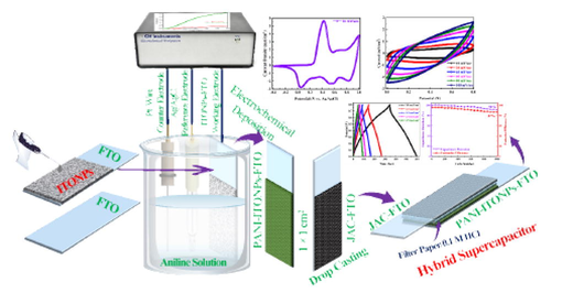
In this study, hierarchical polyaniline (PANI) nanosheets were electrochemically deposited on indium tin oxide nanoparticles coated fluorine-doped tin oxide glass (ITONPs-FTO) substrate from an aqueous solution containing 0.5 M aniline and 1 M H2SO4. The ITONPs provide efficient support with high electroactive surface area in the electrochemical deposition of PANI and produce excellent PANI films. The developed PANI film deposited on the ITONPs-FTO electrode was characterized via field-emission scanning-electron microscopy, energy-dispersive X-ray spectroscopy, X-ray diffraction, and X-ray photoelectron spectroscopy. A hybrid supercapacitor (HSC) was fabricated using the developed PANI deposited ITONPs-FTO as a positrode and the jute sticks derived activated carbon nanosheets coated FTO (JAC-FTO) as a negatrode. Because of its high capacitive performance, unique structures of electrode materials, and optimum operating potential window, the fabricated PANI-ITONPs-FTO//JAC-FTO HSC performed excellently in 0.1 M HCl aqueous electrolyte, delivering a high areal capacitance of 318 mF/cm2 at a 1.0 mA/cm2 current density and exhibit a high energy density of 28 µWh/cm2 at a high power density of 400 µW/cm2. Moreover, the HSC exhibits excellent cyclic stability with ∼ 87% Coulombic efficiency and ∼ 91% capacitance retention after 1000 charge–discharge cycles.
Keywords
Polyaniline
ITO nanoparticles
Electrochemical deposition
Jute sticks derived activated carbon
Asymmetric hybrid supercapacitor

1 Introduction
Due to their long cycle life, high power density, and fast charge/discharge activities, supercapacitors will be critical in meeting future energy storage requirements in memory backup systems, hybrid electric vehicles, and industrial energy management (Miller and Simon 2008, Simon and Gogotsi 2008, Shah et al., 2022a, 2022b, 2022c). However, their low energy density than their counterparts (batteries) makes them appropriate for a limited range of applications (Zhu et al., 2011, Yaseen et al., 2021). To overcome energy density limitations, hierarchical nanostructured or nanoporous materials that stimulate the specific capacitance of electrodes are being developed. Another effective way to overcome the energy density (E = 1/2CV2) limitations is to develop hybrid supercapacitors (HSCs), which integrate electrodes' different capacitive and pseudocapacitive behavior to increase the capacitance and ultimately the energy density (Zhu et al., 2011, Wei et al., 2019, Shah et al., 2022a, 2022b, 2022c).
According to their charge storage mechanisms, supercapacitors are typically categorized into three major classes: (i) electrochemical double-layer supercapacitors (EDLCs), (ii) pseudocapacitors, and (iii) HSCs. EDLCs use carbonaceous materials (such as activated carbon) (Mohamedkhair et al., 2020, Shah et al., 2021a, 2021b, 2021c, 2022a, 2022b, 2022c) as positrode and negatrode for electrochemical energy storage by adsorbing or desorbing electrolyte ions and produce a double layer at the electrode electrolyte interface. Whereas, pseudocapacitors use redox active materials (such as conducting polymers and transition metal oxides) (Zhou and Xu 2016, Shakil et al., 2021, Hasan et al., 2022, Islam et al., 2022, Shah et al., 2022a, 2022b, 2022c) to store charges via fast reversible redox reactions. Whereas HSCs combine the overall performance of EDLCs and pseudocapacitors by using carbonaceous and redox-active materials and enhance the energy density, power density, and specific capacitance (Muzaffar et al., 2019, Zhang et al., 2022).
Because of its easy synthetic protocol, low cost, electrochemical reversibility, mechanical flexibility, fast switching, low toxicity, and comparatively high electrical conductivity, polyaniline (PANI) is a promising positrode material for HSCs (Wang et al., 2006, Ma et al., 2015, Shah et al., 2020, 2022a, 2022b, 2022c). However, PANI has a low-rate capability, narrow operating potential window (OPW), and poor cyclic stability. A homogeneous, well ordered, and nanometer sized structure be required to improve the PANI-based electrodes electrochemical performance. Various synthesis protocols have been used to prepare PANI; however, the electrochemical deposition of PANI could be considered as an efficient technique for developing highly efficient and stable PANI electrodes for supercapacitors (Shah et al., 2020, 2022a, 2022b, 2022c). Along with the various electrochemical deposition parameters, i.e., deposition time, deposition potential, and deposition medium, the substrate has a more pronounced effect on the electrochemical properties of prepared PANI films (Dinh and Birss, 2000). Particularly, the substrate modification with conductive nanometals before electrodeposition of PANI has a considerable effect as a nanomaterials-modified substrate provides a large electroactive surface area. This large electroactive surface area allows to deposit of large amounts of PANI easily, i.e., ultimately, a large surface area of PANI. The advancements made in recent years have demonstrated the importance of a sustained effort focused on various nanomaterials for electrochemical applications (Kang et al., 2010, Shaikh et al., 2015, Alshalalfeh et al., 2016, Kawde et al., 2017, Abu Nayem et al., 2021a, 2021b, Islam et al., 2021, Usman et al., 2021). Recently, we have shown that conductive indium tin oxide nanoparticles (ITONPs) could be deposited on substrate electrodes to increase their electroactive surface and electrocatalytic properties toward sulfide electrooxidation (Aziz et al., 2017, 2018, Shah et al., 2021a, 2021b, 2021c). The ITONPs-modified electrode showed much better electrochemical properties compared to that of counter bulk electrodes (Aziz et al., 2017, 2018, Akanda et al., 2020, Shah et al., 2021a, 2021b, 2021c). We also selected the different methods for homogeneous deposition of ITONPs for the different substrates. As an example, we homogeneously deposited the ITONPs by drop-drying of the aqueous solution of ITONPs on a glassy carbon electrode (Aziz et al., 2018), whereas we used linker molecules to homogeneously deposit of ITONPs on bulk ITO electrode by a similar drop-drying method (Aziz et al., 2017). Other researchers have also prepared ITONPs films using spin coating, electrospinning, inkjet printing, and thermal decomposition (Liu et al., 2014, Mierzwa et al., 2018, Gilshtein et al., 2021, Shah et al., 2021a, 2021b, 2021c). The aqueous solution-based drop-drying method is the simplest one as this is straightforward and has no requirements for any expensive and toxic chemicals and sophisticated instrumentations. However, successfully homogeneous deposition by the drop-drying method partially depends on the properties of the substrate. It is noted that fluorine-doped tin oxide coated glass (FTO) substrate is crystalline in nature and has a zig-zag surface which could be suitable for homogeneous deposition of ITONPs by drop-drying method to provide high surface area (Aziz et al., 2015). As a result, this ITONPs-modified FTO could be counted as a promising electrode material to electrodeposition of PANI with high specific surface area (SSA) and ultimately a high-performance electrode of supercapacitor. Similarly, a suitable negatrode is required to accomplish a good performance rate at a high energy density of HSCs (Gao et al., 2012, Xu et al., 2020a, 2020b, Li et al., 2021). Due of their large SSA, high electrical conductivity, and superior mechanical properties, biomass-derived carbon materials have been identified as ideal candidate materials for supercapacitors (Chang et al., 2018, Ahammad et al., 2019, Aziz et al., 2020, Roy et al., 2021, Shah et al., 2021a, 2021b, 2021c). As an example, we fabricated symmetric EDLC supercapacitor using highly porous jute sticks derived activated carbon nanosheets (JAC) which possess proper combination of and macro-, meso-, and micro- pores (Shah et al., 2021a, 2021b, 2021c). This carbon could be used as cathode materials to fabricate HSCs.
In this study, we have used ITONPs-coated on FTO (ITONPs-FTO) prepared by drop-drying as a substrate for electrochemical deposition of PANI from an aqueous solution containing 1 M H2SO4 and 0.5 M aniline. The ITONPs provide efficient support in the electrochemical deposition of PANI and produce excellent PANI films. The developed PANI deposited on ITONPs-FTO was used as a positrode, and the JAC coated FTO (JAC-FTO) as a negatrode of the HSC. The fabricated PANI-ITONPs-FTO//JAC-FTO HSC performed excellently in 0.1 M HCl electrolyte and delivered a high energy density at a high power density of 28 µWh/cm2 and 400 µW/cm2, respectively.
2 Experimental
2.1 Materials
In the present study, aniline (ACS reagent ≥ 99.5%), sulfuric acid (H2SO4; ACS reagent 99.999%), sodium bicarbonate (NaHCO3), N-Methyl-2-pyrrolidone (NMP), hydrochloric acid (HCl; ACS reagent 37%), Whatman filter papers (grade 201), polyvinylidene fluoride (PVDF; average Mw ∼ 534000), fluorine doped tin oxide coated glass (FTO; surface resistivity ∼ 7 Ω/sq), and indium tin oxide nanoparticles (ITONPs; particle size 18 nm, 20 wt% in H2O) were purchased from Sigma Aldrich (https://www.sigmaaldrich.com). The Specialty Gases Company Limited, Jubail, Kingdom of Saudi Arabia supplied high purity nitrogen (N2) gas. Jute sticks were collected from Mominpur-Keshabpur, Jessore, Bangladesh. A water purification system (Barnstead Nanopure, Thermo Scientific, USA) was used to acquire deionized (DI) water.
2.2 Fabrication of ITONPs modified FTO electrode
Initially, the sigma Aldrich ITONPs solution (20 wt% in H2O) was diluted with DI water sonicated for 30 min to get 1 mg/ml solution. 100 µl from the prepared ITONPs solution was dropped onto the FTO substrate (geometrical working area 1 × 1 cm2) and dried under ambient conditions for 12 h. Fig. 1a and Fig. 1b shows the digital photographs of bare FTO and ITONPs-FTO, respectively. The digital photograph of the bare FTO and ITONPs-FTO clearly demonstrated the homogeneous film formation of ITONPs on FTO by this drop-drying method.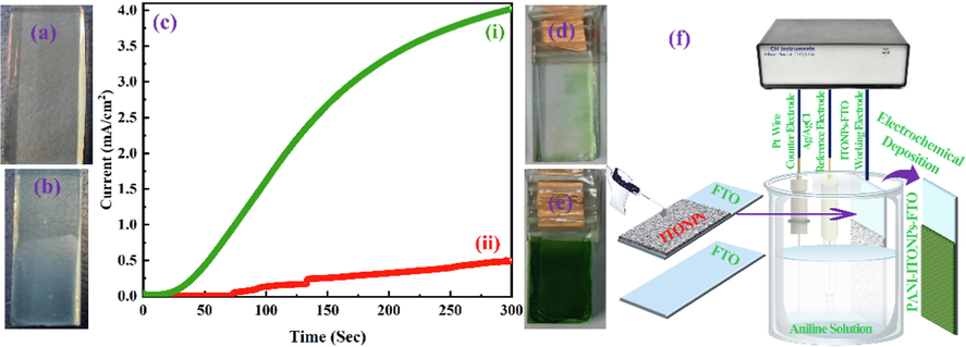
Digital photographs of the (a) bare FTO and (b) ITONPs-FTO substrates. (c) Chronoamperometric curves for electrochemical deposition of PANI on (i) ITONPs-FTO and (ii) bare FTO at + 0.85 V vs. Ag/AgCl using amperometric i-t technique. Digital photographs of (d) PANI-FTO and (e) PANI-ITONPs-FTO electrodes. (f) Schematic representation for the step-by-step fabrication of PANI-ITONPs-FTO electrode.
2.3 Effect of ITONPs in the electrochemical deposition of PANI
For studying the effect of ITONPs in the electrochemical deposition of PANI, PANI was electrochemically deposited on bare FTO and ITONPs-FTO by an amperometric (current–time transient) technique using a similar procedure as reported by our group (Shah et al., 2020, 2022a, 2022b, 2022c). The operational parameters were selected to be + 0.85 V vs. Ag/AgCl as the deposition potential and 300 s as the deposition time. The electro-polymerization solution consisted of 1.0 M H2SO4 and 0.5 M aniline. The working area for the deposition of PANI on the substrates was selected to be 1 × 1 cm2 for efficient growth to be employed as a positrode in the HSC. Amperometric experiments were performed to deposit PANI on FTO and ITONPs-FTO substrates. The developed electrodes were gently rinsed with DI water and allowed to dry overnight under an ambient atmosphere. As shown in Fig. 1c, the deposition of PANI on ITONPs-FTO exhibited a high current density and produced a smooth, homogeneous, and compact two-dimensional PANI film. The produced PANI film was green in color and strongly adhered to the ITONPs-FTO substrate. This developed electrode will be termed as PANI-ITONPs-FTO in the rest of the paper for simple presentation. A similar experiment was performed on a bare FTO substrate, which exhibited a very low amperometric current, and the deposition was not good. This developed electrode will be termed as PANI-FTO in the rest of the paper for simple presentation. The digital photographs of PANI-FTO (Fig. 1d) and PANI-ITONPs-FTO electrodes (Fig. 1e) also demonstrated that the PANI films are homogeneous and adequately adhered to the ITONPs-FTO as compared to bare FTO. Various reports are also available by the direct deposition of PANI on a bare ITO coated glass substrate (Mohd et al., 2012, Mitchell et al., 2015, Aziz et al., 2017, Shah et al., 2020). However, zigzag like surface of FTO provides a high surface area for the tremendous deposition of ITONPs, which further provide an efficient pathway excellent deposition of PANI. The schematic representation for the step-by-step fabrication of the PANI-ITONPs-FTO electrode is illustrated in Fig. 1f.
2.4 Preparation of JAC
In a similar manner to our previous study (Shah et al., 2021a, 2021b, 2021c), the JAC were synthesized from jute sticks. The jute sticks (biomass) were washed with DI water and dried in an electric vacuum oven at 100 °C for 24 h. The dried jute sticks were cut into small pieces and grinded, with a normal kitchen grinder, to a fine powder. The obtained jute sticks powder was passed through a 100 µm mesh and mixed at a 1:4 ratio with the activating agent (NaHCO3). The mixture was then added to an alumina boat crucible, placed in a tube furnace, and carbonized at 850 °C for 5 h under a N2 environment. In the carbonization process, the heating rate was fixed at 10 °C/min and the cooling rate was fixed at 5 °C/min. The resultant carbonized jute powder was washed with 0.5 M HCl, rinsed twice using DI water, and then filtered to remove additional contaminants from pyrolyzed jute powder that may be produced owing to activation. The filtered carbonized powder was then placed in an electric vacuum oven and dried at 80 °C for 24 h, yielding JAC.
2.5 Fabrication of negatrode and the HSC cell
For the fabrication of negatrode (JAC-FTO), 85 wt% JAC and 15 wt% PVDF were dispersed in NMP solvent and stirred at 60 °C for 5 h to get homogenous slurry. The resulting slurry was cast on bare FTO (1 × 1 cm2) and heated at 80 °C in an electric vacuum oven for 12 h. The HSC cell was assembled using the PANI-ITONPs-FTO as a positrode, the JAC-FTO as a negatrode, and fitted with the separator soaked in 0.1 M HCl electrolyte into a sandwich-type cell's construction (i.e., electrode/separator-electrolyte/electrode). In the rest of the paper, the assembled HSC will be termed as PANI-ITONPs-FTO//JAC-FTO HSC.
2.6 Instrumentations
The electrode materials' phase purity and crystalline structure were investigated using the X-ray diffraction (XRD) technique on a Rigaku Miniflex-II diffractometer with Cu-K-Alpha radiations (=0.15416 nm) operating at 40 kV constant voltage and a 30 mA constant current. It was discovered that the morphology of the electrodes produced could be studied using a high-resolution field-emission scanning electron microscope (FESEM, Quattro S). With the help of an Oxford instruments Xmass detector equipped with the FESEM, we performed energy dispersive X-Ray spectroscopy (EDS). A monochromatic Al-K-alpha monochromatic X-ray source was used to determine the electrode's oxidation states using X-ray photoelectron spectroscopy (XPS; Thermo-Scientific, ESCALAB-250Xi XPS-Microprobe, USA). The electrochemical measurements were carried out on a computer-controlled electrochemical workstation (CH Instrument 760E), which was used for the entire experiment.
2.7 Electrochemical measurements
Galvanostatic charge/discharge (GCD), cyclic voltammetry (CV), and electrochemical impedance spectroscopy (EIS) measurements were carried out on the PANI-ITONPs-FTO//JAC-FTO HSC in two-electrode configurations using a CHI-760E electrochemical workstation. The areal capacitances (in F/cm2) of the PANI-ITONPs-FTO electrode and PANI-ITONPs-FTO//JAC-FTO HSC were measured from CV curves and GCD profiles by using eq. (1) and eq. (2), respectively (Shah et al., 2021a, 2021b, 2021c, Shah et al., 2022a, 2022b, 2022c).
The energy density (E, Wh/cm2) and power density (P, W/cm2) of the PANI-ITONPs-FTO//JAC-FTO HSC were calculated by using eq. (3) and eq. (4), respectively (Shah et al., 2021a, 2021b, 2021c, Aziz et al., 2022).
3 Results and discussion
3.1 Structural and morphological investigations
3.1.1 FESEM
The surface morphologies of the PANI-ITONPs-FTO, ITONPs-FTO, and bare FTO were characterized via FESEM, and the findings are presented in Fig. 2. Fig. 2a-c presents the FESEM micrographs at different magnifications of the bare FTO substrate, showing faceted grains with sizes in a wide range from ∼ 200 to ∼ 500 nm. Whereas the surface morphology of the ITONPs-FTO substrate is presented in Fig. 2d-f, clearly showing that the zig-zag surface of the FTO surface is covered with ITONPs and form a highly porous ITONPs film. Such homogenously ITONPs film can provide a high surface area for the proper deposition of PANI. As shown in Fig. 2g-i, the ultrathin hierarchical PANI nanosheets with smooth surfaces cover the ITONPs-FTO substrate uniformly and densely. This demonstrates that the electrochemical deposition produced a homogeneous PANI film of hierarchical nanosheet-type nanostructure on the ITONPs-FTO surface. The PANI film on ITO-FTO possesses a lot of nanometer sizes channels which is helpful for easy diffusion of the electrolyte. The morphology of PANI-ITONPs-FTO is quite different from the morphology of PANI-plane ITO. The sheet size of electrodeposited PANI on plane ITO was in micrometer in ranges, i.e., low supercapacitance performance (Shah et al., 2020). Furthermore, because PANI is directly deposited on the ITONPs-FTO, the electrodes can be constructed without a binder. As a result, the electrochemically prepared PANI-ITONPs-FTO could be an effective electrode for supercapacitor applications.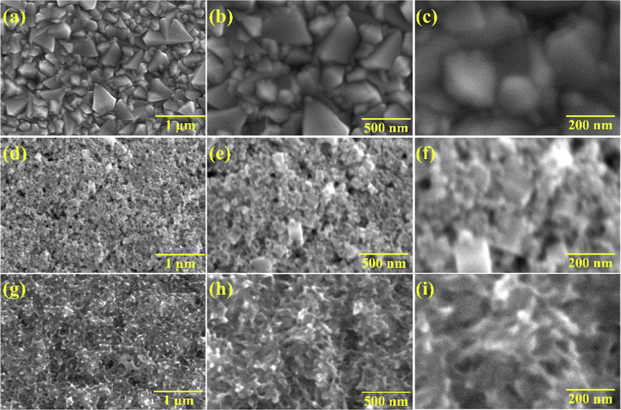
FESEM images of (a-c) bare FTO, (d-f) ITONPs-FTO, (g-i) PANI-ITONPs-FTO electrode at different magnifications.
3.1.2 EDS
The EDS analysis and elemental mapping confirmed the chemical composition of PANI and ITONPs on the FTO surface. The EDS spectrum (Fig. 3a) represents the relevant peaks corresponding to the elements carbon (C), nitrogen (N), indium (In), tin (Sn), and oxygen (O), demonstrating the existence of PANI and ITONPs. Similarly, the fluorine (F) peak along with the Sn and O peaks confirmed the effect of the FTO substrate. Whereas no extra elemental peaks were identified, confirming no contaminants in the produced PANI-ITONPs-FTO electrode. The elemental mapping images, displayed in Fig. 3b, illustrate the uniform distribution of the corresponding elements, i.e., C, O, Sn, In, F, and N on the PANI-ITONPs-FTO electrode surface.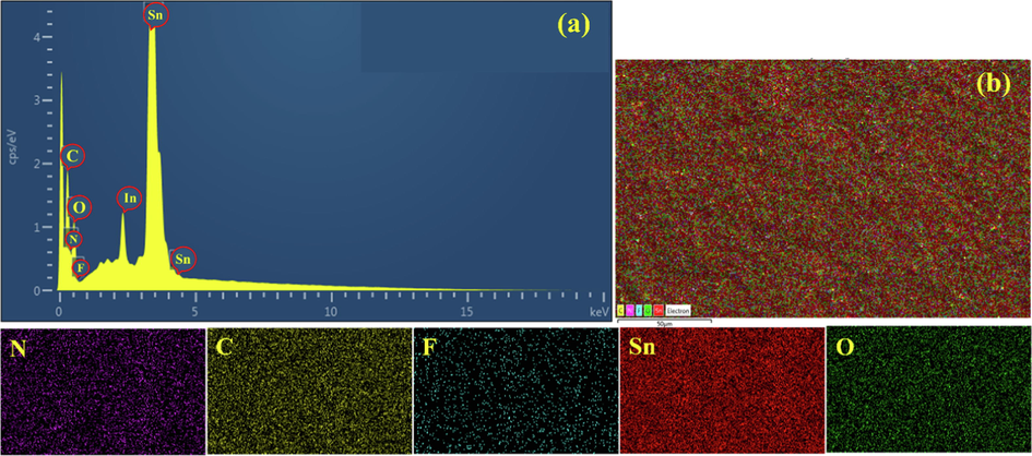
(a) EDS spectrum of PANI-ITONPs modified FTO, (b) EDS overall elemental mapping and the corresponding elemental distributions of PANI-ITONPs-FTO electrode.
3.1.3 XRD
The purity, phase, and crystallinity of the electrochemical deposited PANI on ITONPs-FTO substrate were determined using XRD measurements. Fig. 4 demonstrates the XRD patterns of bare FTO, ITONPs-FTO, and PANI-ITONPs-FTO. The XRD pattern of the FTO substrate represents the typical diffraction peaks at around 2θ = 27°, 35°, 39°, 52°, 55°, 62°, 67°, and 79° of the FTO conductive glass substrate, which are assigned to tetragonal SnO2 (JCPDS card no. 41–1445) (Peng et al., 2011, Kong et al., 2017). Similarly, the XRD pattern ITONPs-FTO consisted of two sets of peaks for FTO used as a substrate and the ITONPs. All the characteristic diffraction peaks of ITONPs at around 2θ = 23°, 31°, 32°, 36°, 38°, 46°, 57°, 61°, and 72° are ascribed to the In2O3 (JCPDS card no. 71–2195) (Liu et al., 2018). Finally, the XRD pattern of the PANI-ITONPs-FTO electrode consisted of the three sets of peaks occurring from the FTO, ITONPs, and PANI. PANI-ITONPs-FTO displayed two sharp peaks between 2θ = 10° to 20°, corresponding to (1 2 1) and (1 0 0) diffraction planes of the PANI due to their highly crystalline nature. The intense peak at around 2θ = 18° could be ascribed to the (1 0 0) diffraction plan of PANI and is ascribed to the perpendicular and parallel polymer chain periodicity of the PANI in its emeraldine base form (Zhou et al., 2014, Wang et al., 2017, Padmapriya et al., 2018). Such high crystalline PANI could provide an efficient pathway for the electrolyte ion diffusion and increase the possibility to prepare high-performance supercapacitor electrode materials (Wang et al., 2017, Chen et al., 2021). The PANI with high crystallinity provide more active sites for electrolyte ion diffusion and Faradaic redox reactions, thus, the prepared PANI-ITONPs-FTO exhibit excellent rate capability and high specific capacitance (Pang et al., 2017). As a reference, the XRD data of commercial PANI powder was recorded (inset of Fig. 4), which shows the major peaks at 2θ < 20°. This further confirm that the diffraction peaks at 2θ = 10° to 20° in the XRD pattern of PANI-ITONPs-FTO are related to the electrochemically deposited PANI over the ITONPs-FTO substrate.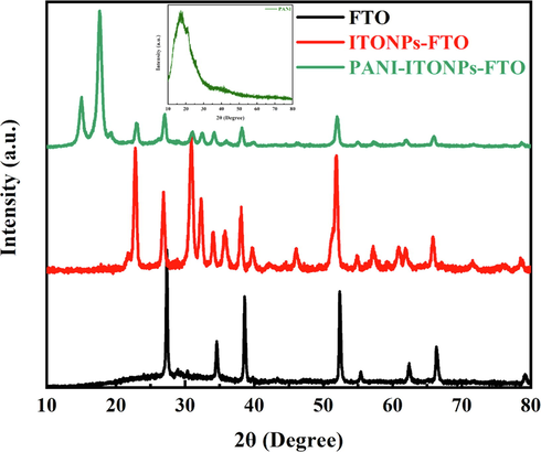
XRD patterns of bare FTO, ITONPs-FTO, and PANI-ITONPs-FTO. The inset shows the XRD pattern of commercial PANI powder.
3.1.4 XPS
XPS is a sophisticated technique used to determine the oxidation states existing in a sample and determine functionalities for faradaic/non-faradaic reactions during the charging and discharging of supercapacitors (Peng et al., 2015, Xu et al., 2020a, 2020b, He et al., 2022). The XPS analysis was carried out to confirm the chemical states of the PANI-ITONPs-FTO. The wide range of XPS survey spectrum is shown in Fig. 5a, which clearly shows C1s, N1s, O1s, In3d, and Sn3d as the major elements and S2p as the minor trace element. The high resolution deconvoluted C1s spectra in Fig. 5b shows three major peaks at binding energies of 284.6, 286.1, and 287.8 eV, which corresponds to the existence of C – C, C – N, and C – O/C = O bonds in PANI (Peng et al., 2015, Shah et al., 2022a, 2022b, 2022c). The high resolution deconvoluted N1s spectrum (Fig. 5c) exhibits two major peaks centered at around binding energies of 402.3 and 398.7 eV, indicating the presence of N+ and = N- groups, respectively. The high resolution deconvoluted In3d spectrum (Fig. 5d) shows two asymmetric In3d5/2 and In3d3/2 peaks of ITONPs positioned at around 445.6 eV and 453 eV, respectively (Pujilaksono et al., 2005). The high resolution deconvoluted Sn3d spectrum (Fig. 5e) shows the Sn3d5/2 and Sn3d3/2 peaks of ITO at around 485.8 and 495.4 eV, respectively (Pujilaksono et al., 2005). The high resolution deconvoluted O1s spectrum (Fig. 5f) shows peaks at 531.2 eV and 532.9 eV, indicating the C = O bond and C – OH/C – O – C bonds, respectively. The incorporation of SO42– ions during the electrochemical deposition of PANI in the H2SO4 acid bath was defined by the existence of the S2p state (Fig. 5g) in the PANI-ITONPs-FTO electrode.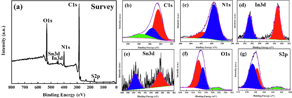
XPS spectra of the PANI-ITONPs-FTO electrode; (a) survey spectrum and high resolution deconvoluted spectra of (b) C1s, (cN1s, (d) In3d, (e) Sn3d, (f) O1s, and (g) S2p.
3.2 Electrochemical investigations
The electrochemical performances of the ITONPs-FTO and bare FTO substrates were investigated in a three-electrode electrochemical cell. The investigated substrate, Ag/AgCl (sat. KCl), and platinum wire were used as working, reference, and counter electrodes, respectively. Fig. 6a compares the CV curves of ITONPs-FTO and bare FTO, demonstrating the high electrochemical double layer charging current of ITONPs-FTO compared with bare FTO in a wide OPW from −0.1 V to 1.0 V vs. Ag/AgCl in 0.1 M HCl aqueous electrolyte at the same scan rate of 50 mV/s. The CV curves of the ITONPs-FTO substrate in Fig. 6a demonstrate a stable electrochemical performance in a wide OPW. The ITONPs-FTO substrate reveals excellent capacitive behavior with an areal capacitance of ∼ 18 mF/cm2. Therefore, ITONPs-FTO could be considered an efficient substrate material for producing high-performance supercapacitor electrodes. Whereas the CV curves of bare FTO (Fig. 6b) also show the unstable electrochemical behavior of the FTO substrate in the applied potential range and can deliver a very low areal capacitance (∼0.2 mF/cm2).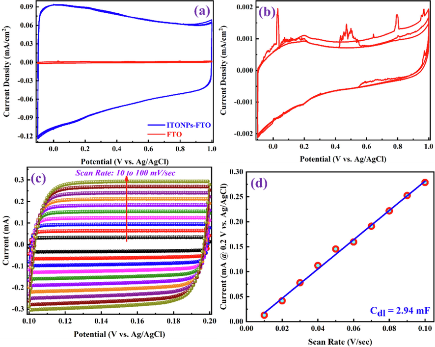
CV curves for (a) comparison of ITONPs-FTO and bare FTO and (b) bare FTO in 0.1 M HCl aqueous electrolyte, recorded at the same scan rate of 0.05 V/s. (c) CV curves of ITONPs-FTO in the non-faradaic region with different scan rates and (d) the corresponding plot of anodic charging current vs. scan rate at a potential of + 0.2 V vs. Ag/AgCl.
Electrochemical surface area (ECSA) is an important parameter representing the electrode materials area reachable to the electrolyte used for charge transfer and/or storage (Dupont et al., 2013, Browne et al., 2016). The ECSA of ITONPs-FTO was estimated by determining the double-layer capacitance (Cdl) from the CV curves using eq. (5) (Deb Nath et al., 2019, Han et al., 2019, Mohamedkhair et al., 2020).
The electrochemical supercapacitor performance of the PANI-ITONPs-FTO electrode was first analyzed in 0.1 M HCl electrolyte using a three-electrode electrochemical cell. PANI-ITONPs-FTO, platinum wire, and Ag/AgCl (sat. KCl) were employed as working, counter, and reference electrodes, respectively. The electrochemical performance of the as-prepared PANI-ITONPs-FTO electrode is shown in Fig. 7. The CV analysis in Fig. 7a was performed to analyze the redox-active pseudocapacitance behavior of the PANI-ITONPs-FTO electrode within the OPW from −0.4 to + 1.0 V (vs. Ag/AgCl) at a scan rate of 10 mV/s. It is well known that PANI exists in three well-defined oxidation states, i.e., pernigraniline, emeraldine, and leucoemeraldine (Jamadade et al., 2010, Yoon et al., 2011, Shah et al., 2020); therefore, the CV curve of the PANI-ITONPs-FTO electrode exhibit three sets of redox peaks. The redox couple that occurred between 0 and 0.4 V (vs. Ag/AgCl) is attributed to the transformation of PANI from the reduced leucoemeraldine state to the partly oxidized emeraldine state (Iram et al., 2012). Whereas the redox couple between + 0.75 V and + 1.0 V (vs. Ag/AgCl) corresponds to the transition of the PANI from leucoemeraldine state to pernigraniline state (Rajendra Prasad and Munichandraiah 2001, Iram et al., 2012). Similarly, the small redox couple between + 0.4 V and + 0.7 V (vs. Ag/AgCl) could be attributed to the faradic conversion of emeraldine to pernigraniline redox states of PANI (Grover et al., 2016). Moreover, Fig. 7b shows the detailed CV curves of the PANI-ITONPs-FTO electrode at different scan rates from 10 to 100 mV/s. It can be seen that the cathodic peaks are shifting to high potentials, and the anodic peaks are shifting to the low potentials with the increase in scan rates. Such a slight shift in peak potentials with the increase in scan rate indicates the contribution from electrochemical polarization and kinetics constraints of PANI (Cong et al., 2013). Similarly, the current densities also increase with the increase in scan rates but the areal capacitance (measured using eq. (1)) of the PANI-ITONPs-FTO electrode decreased from 605 to 262 mF/cm2 with the increase in scan rate from 10 to 100 mV/s. This is due to the fact that at slower scan rates, electrolyte ions are completely diffused into the electrode materials. As a result, the entire active surface of the electrode material can be used to store charge (Liu et al., 2019). At higher scan rates, however, diffusion restricts the movement of electrolyte ions, and only the exterior active surface is used for charge storage (Shah et al., 2021a, 2021b, 2021c). The areal capacitance of PANI-ITONPs-FTO electrode (262 mF/cm2 at a scan rate of 100 mV/s) is even better than the PANI/ITO electrode (70 mF/cm2 at a scan rate of 100 mV/s) reported in the literature (Shah et al., 2020). GCD measurements were performed at different current densities ranging from 1.0 to 5.0 mA/cm2 to reveal the precise electrochemical capacitive performances of the PANI-ITONPs-FTO electrode. All of the GCD profiles in Fig. 7c have non-linear quasi-triangular shapes with severe polarization, indicating that the PANI-ITONPs-FTO electrode is pseudocapacitive in nature (Cong et al., 2013, Grover et al., 2016). The areal capacitances of the PANI-ITONPs-FTO electrode were measured according to eq. (2) which demonstrated that the specific capacitance decrease from 512 to 267 mF/cm2 with the increase in current densities from 1.0 mA/cm2 to 5.0 mA/cm2. This decreasing capacitance behavior with increase in current density could be supported by the fact that electrolyte ions have the greatest chance of reaching the overall effective electroactive area of the electrode material at low current densities (Xu et al., 2022). At higher current densities, the diffusion of electrolyte ions slows down. This reduces the effective electroactive area and, as a result, the number of ions that can penetrate into the active material. As a result, at high current densities, the areal capacitance decreases. The areal capacitances calculated from the CV curves at different scan rates and GCD profiles at different current densities of the PANI-ITONPs-FTO electrode are shown in Fig. 7d.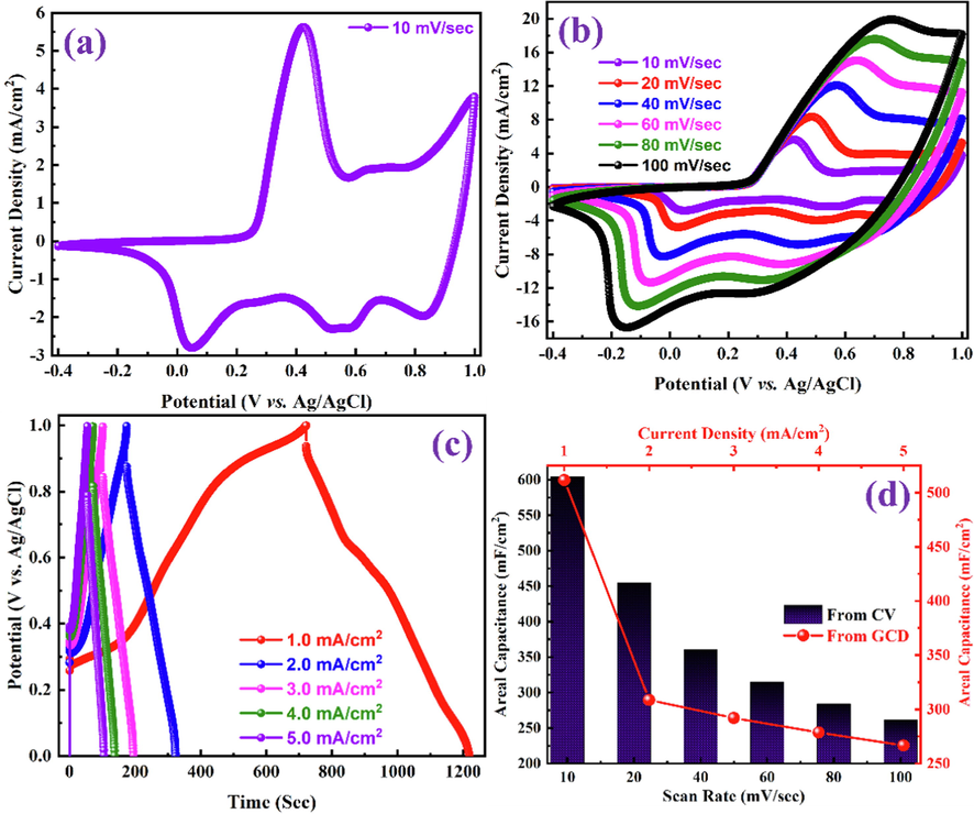
CV curves of the as-prepared PANI-ITONPs-FTO electrode (a) at a scan rate of 10 mV/s and (b) at different scan rates in 0.1 M HCl using a three-electrode electrochemical cell. (c) GCD profiles of the as-prepared PANI-ITONPs-FTO electrode at different current densities in 0.1 M HCl using three-electrode electrochemical cell and (d) the corresponding specific capacitances obtained from CV curves (at different scan rates) GCD profiles (at different current densities).
The electrochemical performance of the fabricated PANI-ITONPs-FTO//JAC-FTO HSC was evaluated using 0.1 M HCl aqueous electrolyte in the two-electrode configuration. The CV profiles of the PANI-ITONPs-FTO//JAC-FTO HSC were obtained in different OPWs at a 50 mV/s scan rate and are shown in Fig. 8a. It was observed that the current density and area under the CV curves increased when the OPW was extended up to 0.8 V; however, beyond 0.8 V, an undesired decrease in the current density was observed, which could be attributed to the decomposition of PANI. Therefore, the optimum OPW from 0 to 0.8 V was chosen as the default OPW in subsequent CV measurements. Fig. 8b shows that the CV curve can sustain a good current density and proper PANI oxidation/reduction peaks in the optimal OPW. The CV curve of PANI-ITONPs-FTO//JAC-FTO HSC shows one oxidation peak at around 0.7 V and one corresponding reduction peak at around 0.5 V, consistent with oxidation and reduction of PANI (Wessling 2010). The two couples of redox peaks in the CV curves of PANI-ITONPs-FTO//JAC-FTO HSC could be attributed to the pernigraniline to emeraldine and leucoemeraldine to emeraldine transitions of PANI, revealing the pseudocapacitance behavior of the prepared PANI (Cong et al., 2013). Fig. 8c shows the CV curves of the PANI-ITONPs-FTO//JAC-FTO HSC at different scan rates from 10 to 100 mV/s. It was found that the HSC device exhibits typical capacitive behavior resulting from both EDLC (due to JAC) and pseudocapacitance (due to PANI). Moreover, the CV curves at high scan rates show a similar shape as those at low scan rates. The areal capacitances of the PANI-ITONPs-FTO//JAC-FTO HSC were calculated from the CV curves at different scan rates using eq. (1). As shown in Fig. 8d, the resultant areal capacitances of the ITONPs-FTO//JAC-FTO HSC are 345, 196, 117, 86, 69, and 58 mF/cm2 at the scan rates of 10, 20, 40, 60, 80, and 100 mV/s, respectively.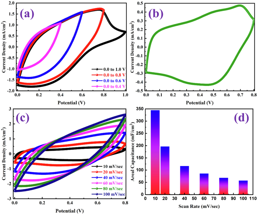
(a) CV curves in different potential windows at 50 mV/s, (b) CV curve at 10 mV/s, (c) CV curves at different scan rates, and (d) areal capacitances obtained from the CV curves at different scan rates of PANI-ITONPs-FTO//JAC-FTO HSC using 0.1 M HCl electrolyte.
The GCD measurements of the developed PANI-ITONPs-FTO//JAC-FTO HSC were evaluated in 0.1 M HCl electrolyte. As shown in Fig. 9a, the GCD profiles exhibit symmetrical quasi-triangular shapes in the OPW from 0 to 0.8 V at the current density of 1.5 mA/cm2. Whereas beyond 0.8 V, there is an unusual distortion along with a high IR drop occur in the GCD profile, which further demonstrates the good pseudocapacitive behavior of the PANI-ITONPs-FTO//JAC-FTO HSC in the OPW from 0 to 0.8 V. Therefore, the potential from 0 to 0.8 V was selected as the stable OPW range for further electrochemical measurements. The capacitive performance of the PANI-ITONPs-FTO//JAC-FTO HSC at different current densities was determined through GCD measurements, as shown in Fig. 9b. All the GCD profiles retain symmetrical quasi-triangular shapes at different current densities from 1.0 to 1.5 mA/cm2 under the optimal OPW from 0 to 0.8 V, manifesting the high reversibility between the charge and discharge processes (Islam et al., 2020, Shah et al., 2020, Ashraf et al., 2021, Shah et al., 2021a, 2021b, 2021c, 2022a, 2022b, 2022c). Similarly, the presence of a negligible IR-drop indicates the presence of a high-performance HSC with low resistance and high charge storage. Because of the conductive polymer PANI, it is possible that conductivity was improved, and because of the ITONPs, a significant electrode/electrolyte contact was possible. On the surface of ITONPs, the high compatibility and proper adherence of the PANI have allowed for a well-behaved electrochemical deposition. The areal capacitances of the PANI-ITONPs-FTO//JAC-FTO HSC at different current densities are also calculated from the GCD profiles using eq. (2). According to the calculation results, the PANI-ITONPs-FTO//JAC-FTO HSC can deliver an excellent areal capacitance of 318 mF/cm2 at a current density of 1.0 mA/cm2, which have been attributed to the proper compatibility of PANI with the ITONPs, that significantly enhances the charge transfer efficiency between the ITONPs and the highly conducting PANI network. The areal capacitances at different current densities were also calculated, and the results are shown in Fig. 9c. The network topology of the PANI-ITONPs-FTO electrode would have facilitated faster charge transfer kinetics, lowering the IR drop and increasing the HSC's charge storage capacity. The effectively activated carbon electrode (JAC-FTO), on the other hand, can compensate for the conductive polymer and result in improved electrochemical performance.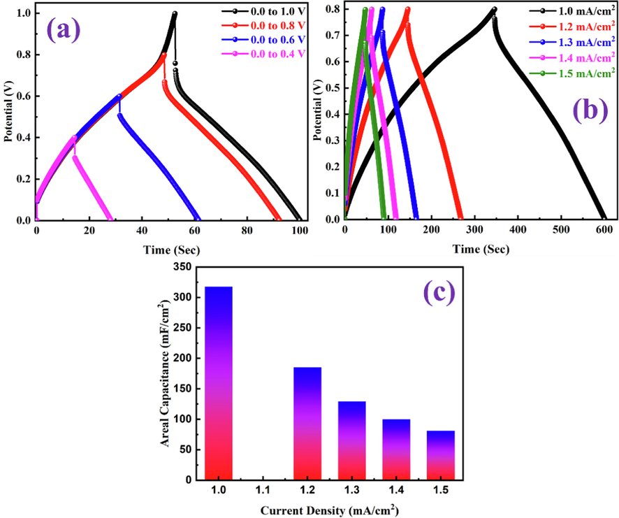
(a) GCD curves in different potential windows at 1.5 mA/cm2, (b) GCD curves at different current densities, and (c) areal capacitances obtained from the GCD curves at different current densities of PANI-ITONPs-FTO//JAC-FTO HSC using 0.1 M HCl solution.
The HSC device is only viable if it has the capability to deliver high energy and power densities. The energy density of power density was calculated from GCD measurements of the PANI-ITONPs-FTO/JAC-FTO HSC using eq. (3) and eq. (4), respectively. A maximum energy density of 28 µWh/cm2 was obtained at a high power density of 400 µW/cm2. Fig. 10a presents the typical Ragone plot of energy density versus power density, showing the amount of energy and power density relationships; even at a high power density of 600 µW/cm2, the energy density is still very high at 7.0 µWh/cm2. To ensure the practical application of ITONPs-FTO//JAC-FTO HSC, we conducted a cycling stability test, as shown in Fig. 10b. Interestingly, the fabricated ITONPs-FTO//JAC-FTO HSC shows excellent cycling stability with ∼ 91% capacitance retention and ∼ 87% Coulombic efficiency after 1000 GCD cycles. The areal capacitances, energy densities, and power densities of the ITONPs-FTO//JAC-FTO HSC are summarized in Table 1. However, the electrochemical performance of the ITONPs-FTO//JAC-FTO HSC is higher than the majority of the PANI based HSCs reported in the literature, as comparative analysis is summarized in Table 2. EIS is another powerful technique for determining the supercapacitor electrode materials conductivity. EIS of the HSC was measured at frequencies ranging from 1.0 Hz to 0.1 MHz. The Nyquist plots of fabricated ITONPs-FTO//JAC-FTO HSC before and after 1000 GCD cycles are shown in Fig. 10c and 10d. The plot shows a semicircle in the high-frequency zone and a quasi-vertical line in the low-frequency region. The x-intercept in the high-frequency zone was used to determine the solution resistance (Rs; ∼22.2 Ω before stability and ∼ 23.8 Ω after stability), and the diameter of the semicircle was used to compute the charge transfer resistance (Rct; ∼2 Ω before stability and ∼ 3 Ω after stability). With a decrease in frequency, the slope of the Nyquist plot shifts from low to higher angles, indicating the pseudocapacitive charge storage process (Javed et al., 2019). Such EIS parameters could be extracted by fitting the equivalent circuit diagram of the Nyquist plot as shown in the inset of Fig. 10c. In addition, EIS data show that fast electron transmission and significant ion diffusion are present in the system. The low resistance could be caused by adherent PANI deposition on the ITONPs-FTO substrate. The improved conductivity and the excellent electrode/electrolyte contact is an advantage of binder-free deposition. Because of these facts, it has been confirmed that electrolyte ions diffuse efficiently throughout the PANI framework, which results in improved high-rate capacitive performance at higher current densities (Li et al., 2020). The PANI-ITONPs-FTO electrode wettability in the 0.1 M HCl electrolyte may have been improved because of the proper HSC design. The uniformly distributed porous network of PANI nanosheets on ITONPs-FTO and JAC-FTO substrates and their hydrophilic functional group allows the proper diffusion of electrolyte ions which ultimately enhance the overall performance of the ITONPs-FTO//JAC-FTO HSC.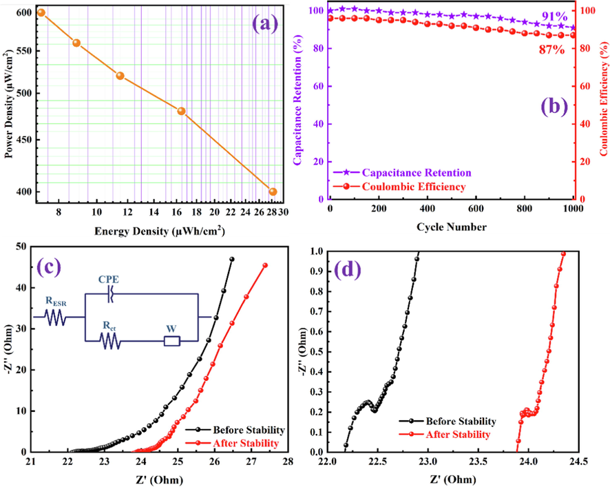
(a) Ragone plot, (b) capacitance retention and Coulombic efficiency with 1000 GCD cycles, and (c) Nyquist plots showing the curves before and after 1000 GCD cycles (the inset shows equivalent circuit diagram) and (d) the maximized portion of the Nyquist plot at higher frequencies of PANI-ITONPs-FTO//JAC-FTO HSC using 0.1 M HCl electrolyte.
From CV
From GCD
Scan Rate (mV/s)
Areal Capacitance (mF/cm2)
Current Density (mA/cm2)
Areal Capacitance (mF/cm2)
Energy Density (µWh/cm2)
Power Density (µW/cm2)
10
345
1.0
318
28
400
20
196
1.2
185
16
480
40
117
1.3
129
11
520
60
86
1.4
100
9
560
80
69
1.5
81
7
600
100
58
Positrode
Negatrode
Electrolyte
Areal capacitance (mF/cm2)
Current density (mA/cm2)
Energy density (µWh/cm2)
Power density (µW/cm2)
Cyclic Stability (% @ No. of Cycles)
Ref.
PANI/GP
PANI/GP
PVA/H2SO4
176
0.2
17.1
250
74.8 @ 500
(Li et al., 2019)
PHE-PANI
CNTs
1 M H3PO4
131
0.5
11.6
79.9
87.3 @ 5000
(Jia et al., 2018)
CFY/CNFs/PANI
CFY/CNFs
EMIMBF4
234
0.1
21
0.52
90 @ 8000
(Mao et al., 2018)
GF/PANI
GF/PANI
1 M H2SO4
357.1
1.0
7.93
230
78.9 @ 5000
(Zheng et al., 2019)
PANI/CNTs/CC
CNTs/CC
1 M NaNO3
30.69
0.5
0.16
20
71 @ 8000
(Aswathy et al., 2021)
PANI
GQDs
PVA/H3PO4
210 μF/cm2
15.0 μA/cm2
0.029
7.46
85.6 @ 1500
(Liu et al., 2013)
SP/PANI
SP/PANI
PVA/H2SO4
149.3
0.5
13.0
400
81.2 @ 5000
(Hou et al., 2020)
PANI-ITONPs-FTO
JAC-FTO
0.1 M HCl
318
1.0
28
400
91 @ 1000
This Work
4 Conclusions
In conclusion, a novel and long-lasting HSC based on hierarchical PANI nanosheets has been successfully fabricated and tested. The PANI nanosheets film deposited on highly electroactive and simply prepared ITONPs-FTO substrate was used as the positrode and JAC-FTO was used as the negatrode in the developed HSC using 0.1 M HCl as aqueous electrolyte. PANI nanosheets film was electrochemically deposited on ITONPs-FTO substrate from an aqueous solution comprising 1 M H2SO4 and 0.5 M aniline. The ITONPs provide effective support that results in high-quality PANI films. A combination of its high capacitive performance, unique electrode material structures, and optimal OPW enabled the fabricated HSC to perform admirably in 0.1 M HCl electrolyte, providing a high areal capacitance of 318 mF/cm2 at a 1.0 mA/cm2 current density and a high energy density of 28 µWh/cm2 at a power density of 400 µW/cm2. Aside from that, the HSC has outstanding cyclic stability, with capacitance retention of ∼ 91% and Coulombic efficiency of ∼ 87% after 1000 charge–discharge cycles. We expect that using a suitable substrate (i.e., ITONPs) to develop PANI electrodes with sufficient potential and optimized capacitance will enhance the performance of HSCs significantly. These promising discoveries may pave the way for developing polymer based HSCs for high-performance energy storage applications.
Acknowledgments
The authors would like to acknowledge the support provided by the Deanship of Scientific Research (DSR) at King Fahd University of Petroleum & Minerals (KFUPM) for funding this work through the project No. DF191038.
References
- Electrochemical Sensing Platforms of Dihydroxybenzene: Part 2 – Nanomaterials Excluding Carbon Nanotubes and Graphene. Chem. Rec.. 2021;21:1073-1097.
- [CrossRef] [Google Scholar]
- Electrochemical Sensing Platforms of Dihydroxybenzene: Part 1 – Carbon Nanotubes, Graphene, and their Derivatives. Chem. Rec.. 2021;21:1039-1072.
- [CrossRef] [Google Scholar]
- Activated jute carbon paste screen-printed FTO electrodes for nonenzymatic amperometric determination of nitrite. J. Electroanal. Chem.. 2019;832:368-379.
- [CrossRef] [Google Scholar]
- Review—Recent Advancements in the Utilization of Indium Tin Oxide (ITO) in Electroanalysis without Surface Modification. J. Electrochem. Soc.. 2020;167:037534
- [CrossRef] [Google Scholar]
- Electrochemical Investigation of Gold Nanoparticle-Modified Glassy Carbon Electrode and its Application in Ketoconazole Determination. Aust. J. Chem.. 2016;69:1314-1320.
- [CrossRef] [Google Scholar]
- A High-Performance Asymmetric Supercapacitor Based on Tungsten Oxide Nanoplates and Highly Reduced Graphene Oxide Electrodes. Chem. Eur. J.. 2021;27:6973-6984.
- [CrossRef] [Google Scholar]
- Polyaniline/multi-walled carbon nanotubes filled biopolymer based flexible substrate electrodes for supercapacitor applications. J. Energy Storage.. 2021;35:102256
- [CrossRef] [Google Scholar]
- Preparation and Utilization of Jute-Derived Carbon: A Short Review. Chem. Rec.. 2020;20:1074-1098.
- [CrossRef] [Google Scholar]
- Indium Tin Oxide Nanoparticle-modified Glassy Carbon Electrode for Electrochemical Sulfide Detection in Alcoholic Medium. Anal. Sci.. 2018;34:599-604.
- [CrossRef] [Google Scholar]
- Preparation of Indium Tin Oxide Nanoparticle-modified 3-Aminopropyltrimethoxysilane-functionalized Indium Tin Oxide Electrode for Electrochemical Sulfide Detection. Electroanal.. 2017;29:1683-1690.
- [CrossRef] [Google Scholar]
- Peat soil-derived silica doped porous graphitic carbon with high yield for high-performance all-solid-state symmetric supercapacitors. J. Energy Storage.. 2022;50:104278
- [CrossRef] [Google Scholar]
- Electrochemical investigation of metal oxide conducting electrodes for direct detection of sulfide. Electroanal.. 2015;27:1268-1275.
- [CrossRef] [Google Scholar]
- Low-Overpotential High-Activity Mixed Manganese and Ruthenium Oxide Electrocatalysts for Oxygen Evolution Reaction in Alkaline Media. ACS Catal.. 2016;6:2408-2415.
- [CrossRef] [Google Scholar]
- Converting Polyvinyl Chloride Plastic Wastes to Carbonaceous Materials via Room-Temperature Dehalogenation for High-Performance Supercapacitor. ACS Appl. Energy Mater.. 2018;1:5685-5693.
- [CrossRef] [Google Scholar]
- Microstructure control for high-capacitance polyaniline. Electrochim. Acta.. 2021;391:138977
- [CrossRef] [Google Scholar]
- Flexible graphene–polyaniline composite paper for high-performance supercapacitor. Energy Environ. Sci.. 2013;6:1185-1191.
- [CrossRef] [Google Scholar]
- The Determination of Electrochemical Active Surface Area and Specific Capacity Revisited for the System MnOx as an Oxygen Evolution Catalyst. Z. Phys. Chem.. 2020;234:979-994.
- [CrossRef] [Google Scholar]
- Defective Carbon Nanosheets Derived from Syzygium cumini Leaves for Electrochemical Energy-Storage. ChemistrySelect.. 2019;4:9079-9083.
- [CrossRef] [Google Scholar]
- Effect of Substrate on Polyaniline Film Properties A Cyclic Voltammetry and Impedance Study. J. Electrochem. Soc.. 2000;147:3775.
- [CrossRef] [Google Scholar]
- Electrochemically active surface area effects on the performance of manganese dioxide for electrochemical capacitor applications. Electrochim. Acta.. 2013;104:140-147.
- [CrossRef] [Google Scholar]
- High-Performance Asymmetric Supercapacitor Based on Graphene Hydrogel and Nanostructured MnO2. ACS Appl. Mater. Interfaces.. 2012;4:2801-2810.
- [CrossRef] [Google Scholar]
- Invisible and Flexible Printed Sensors Based on ITO Nanoparticle Ink for Security Applications. Front. Nanotechnol.. 2021;3
- [CrossRef] [Google Scholar]
- Polyaniline All Solid-State Pseudocapacitor: Role of Morphological Variations in Performance Evolution. Electrochim. Acta.. 2016;196:131-139.
- [CrossRef] [Google Scholar]
- Electronically Double-Layered Metal Boride Hollow Nanoprism as an Excellent and Robust Water Oxidation Electrocatalysts. Adv. Energy Mater.. 2019;9:1803799.
- [CrossRef] [Google Scholar]
- Recent Advances in Carbon and Metal Based Supramolecular Technology for Supercapacitor Applications. Chem. Rec.. 2022;e202200041
- [CrossRef] [Google Scholar]
- Organic-inorganic hybrid electrode engineering for high-performance asymmetric supercapacitor based on WO3-CeO2 nanowires with oxygen vacancies. Appl. Surf. Sci.. 2022;573:151624
- [CrossRef] [Google Scholar]
- Boosting the electrochemical properties of polyaniline by one-step co-doped electrodeposition for high performance flexible supercapacitor applications. J. Electroanal. Chem.. 2020;863:114064
- [CrossRef] [Google Scholar]
- Highly ordered mesostructured silica spheres as template for polyaniline nanofibres: synthesis, characterisation and their electrochemical properties. J. Exp. Nanosci.. 2012;7:27-41.
- [CrossRef] [Google Scholar]
- Recent Advancements in Electrochemical Deposition of Metal-Based Electrode Materials for Electrochemical Supercapacitors. Chem. Rec.. 2022;e202200013
- [CrossRef] [Google Scholar]
- Graphene and Carbon Nanotubes-based Electrochemical Sensing Platforms for Dopamine. Chem. Asian J.. 2021;16:3516-3543.
- [CrossRef] [Google Scholar]
- High yield activated porous coal carbon nanosheets from Boropukuria coal mine as supercapacitor material: Investigation of the charge storing mechanism at the interfacial region. J. Energy Storage.. 2020;32:101908
- [CrossRef] [Google Scholar]
- Studies on electrosynthesized leucoemeraldine, emeraldine and pernigraniline forms of polyaniline films and their supercapacitive behavior. Synth. Met.. 2010;160:955-960.
- [CrossRef] [Google Scholar]
- An ultra-high energy density flexible asymmetric supercapacitor based on hierarchical fabric decorated with 2D bimetallic oxide nanosheets and MOF-derived porous carbon polyhedra. J. Mater. Chem. A.. 2019;7:946-957.
- [CrossRef] [Google Scholar]
- Stretchable and Compressible Supercapacitor with Polyaniline on Hydrogel Electrolyte. J. Electrochem. Soc.. 2018;165:A3792-A3798.
- [CrossRef] [Google Scholar]
- Effect of aging on the electrocatalytic activity of gold nanoparticles. Electrochem. Commun.. 2010;12:1245-1248.
- [CrossRef] [Google Scholar]
- Cathodized Gold Nanoparticle-Modified Graphite Pencil Electrode for Non-Enzymatic Sensitive Voltammetric Detection of Glucose. Electroanal.. 2017;29:1214-1221.
- [CrossRef] [Google Scholar]
- Enhanced photoelectrochemical performance of tungsten oxide film by bifunctional Au nanoparticles. RSC Adv.. 2017;7:15201-15210.
- [CrossRef] [Google Scholar]
- A flexible solid-state supercapacitor based on graphene/polyaniline paper electrodes. J. Energy Chem.. 2019;32:166-173.
- [CrossRef] [Google Scholar]
- Hierarchical mesoporous NiCoP hollow nanocubes as efficient and stable electrodes for high-performance hybrid supercapacitor. Appl. Surf. Sci.. 2021;536:147751
- [CrossRef] [Google Scholar]
- Facile preparation of polyaniline covalently grafted to isocyanate functionalized reduced graphene oxide nanocomposite for high performance flexible supercapacitors. Colloids Surf. A Physicochem. Eng. Asp.. 2020;602:125172
- [CrossRef] [Google Scholar]
- Improved cycling performance and rate stability of ITO-compounded Li2MnSiO4 for lithium-ion batteries. RSC Adv.. 2018;8:9795-9801.
- [CrossRef] [Google Scholar]
- Novel and high-performance asymmetric micro-supercapacitors based on graphene quantum dots and polyaniline nanofibers. Nanoscale.. 2013;5:6053-6062.
- [CrossRef] [Google Scholar]
- Superb Electrolyte Penetration/Absorption of Three-Dimensional Porous Carbon Nanosheets for Multifunctional Supercapacitor. ACS Appl. Energy Mater.. 2019;2:3185-3193.
- [CrossRef] [Google Scholar]
- Macroporous indium tin oxide electrode layers as conducting substrates for immobilization of bulky electroactive guests. Electrochim. Acta.. 2014;140:108-115.
- [CrossRef] [Google Scholar]
- Effect of substituent position on electrodeposition, morphology, and capacitance performance of polyindole bearing a carboxylic group. Electrochim. Acta.. 2015;176:1302-1312.
- [CrossRef] [Google Scholar]
- Enhanced electrochemical properties of hierarchically sheath-core aligned carbon nanofibers coated carbon fiber yarn electrode-based supercapacitor via polyaniline nanowire array modification. J. Power Sources.. 2018;399:406-413.
- [CrossRef] [Google Scholar]
- Benchmarking Hydrogen Evolving Reaction and Oxygen Evolving Reaction Electrocatalysts for Solar Water Splitting Devices. J. Am. Chem. Soc.. 2015;137:4347-4357.
- [CrossRef] [Google Scholar]
- Benchmarking Heterogeneous Electrocatalysts for the Oxygen Evolution Reaction. J. Am. Chem. Soc.. 2013;135:16977-16987.
- [CrossRef] [Google Scholar]
- Highly Interconnected Macroporous and Transparent Indium Tin Oxide Electrode. ChemElectroChem.. 2018;5:397-404.
- [CrossRef] [Google Scholar]
- Electrochemical Capacitors for Energy Management. Science. 2008;321:651-652.
- [CrossRef] [Google Scholar]
- High performance supercapacitor based on multilayer of polyaniline and graphene oxide. Synth. Met.. 2015;199:214-218.
- [CrossRef] [Google Scholar]
- Effect of an activating agent on the physicochemical properties and supercapacitor performance of naturally nitrogen-enriched carbon derived from Albizia Procera leaves. Arab. J. Chem.. 2020;13:6161-6173.
- [CrossRef] [Google Scholar]
- Electrodeposition and characterization of polyaniline films. IEEE Symposium on Humanities, Science and Engineering Research.. 2012;12:1301-1306.
- [CrossRef] [Google Scholar]
- A review on recent advances in hybrid supercapacitors: Design, fabrication and applications. Renew. Sust. Energ. Rev.. 2019;101:123-145.
- [CrossRef] [Google Scholar]
- Storage and evolution of hydrogen in acidic medium by polyaniline. Int. J. Energy Res.. 2018;42:1196-1209.
- [CrossRef] [Google Scholar]
- Facile Synthesis of Polyaniline Nanotubes with Square Capillary Using Urea as Template. Polymers.. 2017;9:510.
- [CrossRef] [Google Scholar]
- A novel fabrication of nitrogen-containing carbon nanospheres with high rate capability as electrode materials for supercapacitors. RSC Adv.. 2015;5:12034-12042.
- [CrossRef] [Google Scholar]
- Facile solution deposition of ZnIn2S4 nanosheet films on FTO substrates for photoelectric application. Nanoscale.. 2011;3:2602-2608.
- [CrossRef] [Google Scholar]
- X-ray photoelectron spectroscopy studies of indium tin oxide nanocrystalline powder. Mater. Charact.. 2005;54:1-7.
- [CrossRef] [Google Scholar]
- Potentiodynamic deposition of polyaniline on non-platinum metals and characterization. Synth. Met.. 2001;123:459-468.
- [CrossRef] [Google Scholar]
- Preparation of Hierarchical Porous Activated Carbon from Banana Leaves for High-performance Supercapacitor: Effect of Type of Electrolytes on Performance. Chem. Asian J.. 2021;16:296-308.
- [CrossRef] [Google Scholar]
- Preparation of Sulfur-doped Carbon for Supercapacitor Applications: A Review. ChemSusChem. 2022;15:e202101282
- [CrossRef] [Google Scholar]
- Polyaniline and heteroatoms–enriched carbon derived from Pithophora polymorpha composite for high performance supercapacitor. J. Energy Storage.. 2020;30:101562
- [CrossRef] [Google Scholar]
- Controlled-Potential-Based Electrochemical Sulfide Sensors: A Review. Chem. Rec.. 2021;21:204-238.
- [CrossRef] [Google Scholar]
- Recent Progress in Carbonaceous and Redox-active Nanoarchitectures for Hybrid Supercapacitors: Performance Evaluation, Challenges, and Future Prospects. Chem. Rec.. 2022;e202200018
- [CrossRef] [Google Scholar]
- Jute Sticks Derived and Commercially Available Activated Carbons for Symmetric Supercapacitors with Bio-electrolyte: A Comparative Study. Synth. Met.. 2021;277:116765
- [CrossRef] [Google Scholar]
- Boosting the Electrochemical Performance of Polyaniline by One-Step Electrochemical Deposition on Nickel Foam for High-Performance Asymmetric Supercapacitor. Polymers.. 2022;14:270.
- [CrossRef] [Google Scholar]
- Present Status and Future Prospects of Jute in Nanotechnology: A Review. Chem. Rec.. 2021;21:1631-1665.
- [CrossRef] [Google Scholar]
- The rhodium complex of bis(diphenylphosphinomethyl)dopamine-coated magnetic nanoparticles as an efficient and reusable catalyst for hydroformylation of olefins. New J. Chem.. 2015;39:7293-7299.
- [CrossRef] [Google Scholar]
- Development of a Novel Bio-based Redox Electrolyte using Pivalic Acid and Ascorbic Acid for the Activated Carbon-based Supercapacitor Fabrication. Asian J. Org. Chem.. 2021;10:2220-2230.
- [CrossRef] [Google Scholar]
- Bismuth-Graphene Nanohybrids: Synthesis, Reaction Mechanisms, and Photocatalytic Applications—A Review. Energies.. 2021;14:2281.
- [CrossRef] [Google Scholar]
- Enhanced Electrochemical Performance by Strongly Anchoring Highly Crystalline Polyaniline on Multiwalled Carbon Nanotubes. ACS Appl. Mater. Interfaces.. 2017;9:43939-43949.
- [CrossRef] [Google Scholar]
- Ordered Whiskerlike Polyaniline Grown on the Surface of Mesoporous Carbon and Its Electrochemical Capacitance Performance. Adv. Mater.. 2006;18:2619-2623.
- [CrossRef] [Google Scholar]
- Mesopore-dominant porous carbon derived from bio-tars as an electrode material for high-performance supercapacitors. J. Saudi Chem. Soc.. 2019;23:958-966.
- [CrossRef] [Google Scholar]
- New Insight into Organic Metal Polyaniline Morphology and Structure. Polymers.. 2010;2:786-798.
- [CrossRef] [Google Scholar]
- High-efficiency electrodeposition of polyindole nanocomposite using MoS2 nanosheets as electrolytes and their capacitive performance. Arab. J. Chem.. 2020;13:6061-6071.
- [CrossRef] [Google Scholar]
- Fused Heterocyclic Molecule-Functionalized N-Doped Reduced Graphene Oxide by Non-Covalent Bonds for High-Performance Supercapacitors. ACS Appl. Mater. Interfaces.. 2020;12:45202-45213.
- [CrossRef] [Google Scholar]
- Advanced Oxygen-Vacancy Ce-Doped MoO3 Ultrathin Nanoflakes Anode Materials Used as Asymmetric Supercapacitors with Ultrahigh Energy Density. Adv. Energy Mater.. 2022;12:2200101.
- [CrossRef] [Google Scholar]
- A Review of Supercapacitors: Materials Design, Modification, and Applications. Energies.. 2021;14:7779.
- [CrossRef] [Google Scholar]
- Electrochemical properties of leucoemeraldine, emeraldine, and pernigraniline forms of polyaniline/multi-wall carbon nanotube nanocomposites for supercapacitor applications. J. Power Sources.. 2011;196:10791-10797.
- [CrossRef] [Google Scholar]
- Vertically Aligned Micropillar Arrays Coated with a Conductive Polymer for Advanced Pseudocapacitance Energy Storage. ACS Appl. Mater. Interfaces.. 2022;14:10805-10814.
- [CrossRef] [Google Scholar]
- Core-Sheath Porous Polyaniline Nanorods/Graphene Fiber-Shaped Supercapacitors with High Specific Capacitance and Rate Capability. ACS Appl. Energy Mater.. 2019;2:4335-4344.
- [CrossRef] [Google Scholar]
- High-operating-voltage all-solid-state symmetrical supercapacitors based on poly(3,4-ethylenedioxythiophene)/poly(styrenesulfonate) films treated by organic solvents. Electrochim. Acta.. 2016;222:1895-1902.
- [CrossRef] [Google Scholar]
- Promoting Oxygen Evolution by Deep Reconstruction via Dynamic Migration of Fluorine Anions. ACS Appl. Mater. Interfaces.. 2021;13:34438-34446.
- [CrossRef] [Google Scholar]
- Polyaniline-decorated cellulose aerogel nanocomposite with strong interfacial adhesion and enhanced photocatalytic activity. RSC Adv.. 2014;4:8966-8972.
- [CrossRef] [Google Scholar]
- Carbon-Based Supercapacitors Produced by Activation of Graphene. Science. 2011;332:1537-1541.
- [CrossRef] [Google Scholar]


