

Translate this page into:
Corrosion and tribological performance of quasi-stoichiometric titanium containing carbo-nitride coatings
⁎Corresponding author at: Atomistilor Street, No. 409, PO BOX MG 05, RO77125, Magurele, Bucharest, Romania. Fax: +40 (0)21 457 57 59. alinava@inoe.ro (Alina Vladescu)
-
Received: ,
Accepted: ,
This article was originally published by Elsevier and was migrated to Scientific Scholar after the change of Publisher.
Peer review under responsibility of King Saud University.
Abstract
Zr, Nb and Si doped TiCN coatings, with (C+N)/(metal + Si) ratios of approximately 1, were deposited on stainless steel and Si wafer substrates using a cathodic arc technique in a mixture of N2 and CH4 gases. The coatings were comparatively analysed for elemental and phase composition, adhesion, anticorrosive properties and tribological performance at ambient and 250 °C. Zr, Nb and Si alloying contents in the coatings were in the range 2.9–9.6 at.%. All the coatings exhibited f.c.c. solid solution structures and had a 〈1 1 1〉 preferred orientation. In the adhesion tests conducted, critical loads ranged from 20 to 30 N, indicative of a good adhesion to substrate materials. The Ti based coatings with Nb or Si alloying elements proved to be resistant to corrosive attack in 3.5% NaCl and of these coatings the TiNbCN was found to have the best corrosion resistance. TiCN exhibited the best tribological performance at 250 °C, while at ambient temperatures it was TiNbCN. Abrasive and oxidative wear was found to be the main wear mechanism for all of the coatings. Of the tested coatings, TiNbCN coatings would be the most suitable candidate for severe service (high temperature, corrosive, etc.) applications.
Keywords
TiCN
TiZrCN
TiNbCN and TiSiCN coatings
Cathodic arc
Corrosion resistance
Friction coefficient and wear resistance

1 Introduction
Cutting tools in the machining industry are required to provide a level of mechanical strength and chemical stability such that they provide both durability and performance. The state of the art suggests that the mechanical requirements can be met; however, corrosion and wear requirements particularly in severe conditions (e.g. high temperatures and corrosive environment) remain problematic (Cramer and Covino, 2003; Arai, 1992; Suh, 1980; Möhring et al., 2015). A wide range of surface engineering, focused on hard coatings, has been suggested to overcome these issues. Coatings include nitrides (TiN (Zhang and Zhu, 1993; Jindal et al., 1999); ZrN (Deng et al., 2008a, 2008b); CrN (Atar et al., 2014; Birol, 2013; Sresomroeng et al., 2011); TiAlN (Jindal et al., 1999; Khrais and Lin, 2007; Kumar et al., 2014)) and carbides (TiC (Klaasen and Kübarsepp, 2004; Prengel et al., 1998) or NbC (Prengel et al., 1998; Mesquita and Schuh, 2012)) due to their high hardness, reduced Young’s modulus, and good resistance to corrosion. They are applied using physical vapour deposition techniques, and processes offering high coating adhesion to the steel substrates, while maintaining a relatively low deposition temperature. This helps to reduce microstructural changes within the substrate (Van Stappen et al., 1995; Friz and Waibel, 2003; Mikuła and Dobrzański, 2007).
Carbo-nitrides of transition metals offer a combination of the properties of nitride and carbide coatings, improving hardness, thermal stability, wear and corrosion resistance and reducing oxidation (Van Stappen et al., 1995; Toth, 1971; Lengauer et al., 1995; Naguib et al., 2012; Kral et al., 1998). In more recent work, alloying with various elements (including Al, V, Nb, W, Mo, Y, Si and B) in the structure of the binary or ternary compounds further improves the mechanical and tribological properties of the coatings (Hauert and Patscheider, 2000; Endrino and Derflinger, 2005; Volovitch et al., 2011; Farzaneh et al., 2011; Kutschej et al., 2005; Kathrein et al., 2005).
In the present paper, alloying elements of Zr, Nb and Si have been added to a TiCN ternary carbo-nitride compound. High C/N coatings were selected, because of their superior tribological performance in both dry and corrosive environments (Jiang et al., 2003; Polcar et al., 2010). The improved tribology can be attributed to the high carbon content in the coating, which leads to the formation of an amorphous free carbon phase (Jiang et al., 2003; Polcar et al., 2010). It also results in increased grain boundaries length impeding corrosive attack (Scully et al., 2007; Boxman et al., 1995; Schwarzer and Richter, 2006; He et al., 2001). The selected coatings are investigated for components requiring protective coatings for both tribological applications in dry environments and under corrosive conditions.
2 Experimental details
The coatings were deposited simultaneously on 316L stainless steel (SS) and Si wafer substrates. This was dependent on the analysis carried out: 316L substrates for elemental and phase compositions, adhesion, corrosion testing, tribological performance and surface profilometry measurements; Si wafers for stress measurements, cross-sectional microstructures and chemical bonds in the films. Samples were prepared using a cathodic arc technique (CAT). CAT offers an alternative for depositing films with good uniformity, high adhesion to metallic substrates, and high-density plasma, which generates an intense ion bombardment at the substrate. In this way, sufficiently high chemical activity of the reactive species is achieved, resulting in thermodynamically driven phase segregation and the formation of nanostructures (Dylla et al., 1997; Boxman et al., 1995). For preparation of the TiCN, TiNbCN and TiSiCN coatings, the deposition chamber was equipped with only one cathode (Ti 100 at.%, Ti85–Nb15 at.%, or Ti88–Si12 at.%). For TiZrCN, two cathodes were used (Ti and Zr). The deposition conditions were selected to obtain films with a C/N ratio of about 2, atomic concentrations for Zr, Nb and Si of 3–9 at.% and thicknesses of ∼3.8 μm. The main process parameters are presented in Table 1.
Total gas (CH4 + N2) flow rate
90 sccm
CH4 flow rate
65 sccm
N2 flow rate
25 sccm
Arc currents
90 A for Zr, 110 A for the other cathodes
Substrate bias voltage
−100 V
Deposition temperature
320 °C
Deposition duration
40–50 min
Elemental composition was determined using a scanning electron microscope (Hitachi 3030PLUS) equipped with energy dispersive X-ray detector (EDS, Bruker). Crystalline structure, phase composition, texture and grain size were obtained by means of X-ray diffraction (XRD) using a Rigaku MiniFlex II diffractometer, with Cu Kα radiation. The crystallite sizes were determined from the XRD peak widths using the Scherrer formula. Chemical bonding structure of the coatings was investigated using a confocal Raman microscope (alpha 300 WITec GmbH.) in backscattering geometry, using an excitation laser radiation at 532 nm. The scattered radiation was collected via a 0.9 NA (100× magnification) objective lens. For spectral analysis it was conducted at 1800 g/mm, providing a resolution of 1.2–1.3 cm−1. Displayed Raman spectra represented single accumulations (60 s) and were raw spectra without any averaging or smoothing.
Coating adhesion was tested according to ISO EN 1071-3:2005. The critical load values (Lc – defined as the load where film flaking starts) were obtained by microscopic examination of the scratch tracks. The residual stress of the coatings was determined by the Stoney equation (Schwarzer and Richter, 2006), using the measurements of the radii of curvature of Si (1 1 1) wafer substrates before and after coating deposition using a surface profilometer (Dektak 150).
The corrosion resistance of the coatings was tested in 3.5% NaCl solution (pH = 8), at room temperature (RT, 22 ± 1 °C), using a VersaSTAT 3 Potentiostat/Galvanostat. Experiments were conducted using a typical three-electrode cell, with a Pt and saturated Ag/AgCl (0.197 V vs. NHE) counter and reference electrodes. The open-circuit potential (EOC) was continuously monitored for 1 h, starting after immersion in the corrosive environment. After the initial period, potentiodynamic polarization measurements from −1 V to +1 V were recorded. All specimens, mounted on the working electrode, were placed in a PTFE sample holder with an exposure area of 1 cm2. The electrochemical measurements were performed with a scanning rate of 0.167 mV/s (as given in ASTM G 59-97). Tests were repeated at least two times for each specimen. The corrosion potential (Ei=0), corrosion current density (icorr), anodic slope (ba) and cathodic slope (bc) were determined by graphical extrapolation of the two branches of the polarization curves in the range of ±50 mV, as per the method detailed in Gostin et al. (2010). The electrochemical parameters were calculated using Versa Studio software (Princeton Applied Research). The polarization resistance (Rp) was calculated using the Stern-Geary equation (Stern and Geary, 1957a):
These parameters were obtained according to the procedure described in Stern and Geary (1957b) and Rybalka et al. (2014).
The tribological behaviour of the coatings was assessed using a TE77 high frequency reciprocating friction rig (Phoenix Tribology, Berkshire, UK). Tests were conducted using a 6 mm AISI 316 pin and a coated plate, with a 5 N normal load, 2 Hz frequency, 12.4 mm stroke length, in air without any fluid lubricant, in controlled humidity (50%) and at ambient temperature and 250 °C. All the experiments were carried out in comparison with carbo-nitride films without alloying elements, taken as reference coatings. The data represent the average of at least three tests for each temperature. The wear rate (K) was calculated by normalizing the worn volume (V) over the normal load (F) and the sliding distance (d):
The worn volume was determined by measuring the cross-sectional areas of the wear scar at 3 points on each track.
3 Results and discussions
3.1 Elemental composition, crystalline structure, chemical bonds and cross-sectional morphology
The elemental compositions of the coatings are given in Table 2. The Zr, Nb and Si contents in the deposited film ranged from 2.9 to 9.6 at.%. The coatings were almost stoichiometric, with (C + N)/metal ratios ranging from 0.97 to 1.06, and C/N ratios between 1.52 and 1.94.
Coating
Elemental composition (at.%)
(C + N)/(metal + Si)
C/N
Ti
Zr
Nb
Si
C
N
O
TiCN
45.8
–
–
–
30.5
16.2
7.5
1.02
1.88
TiZrCN
35.1
10.3
–
–
31.8
16.4
6.4
1.06
1.94
TiNbCN
35.7
–
11.6
–
28.6
17.5
6.6
0.97
1.63
TiSiCN
43.3
–
–
2.6
29.2
19.2
5.7
1.05
1.52
X-ray diffractograms of the TiCN, TiZrCN, TiNbCN and TiSiCN coatings are shown in Fig. 1. The investigated coatings exhibited f.c.c. solid solutions, with preferred orientation in the plane (1 1 1). This texture, commonly reported for the films deposited by CAT (Boxman et al., 1995), is a result of the intense ion bombardment of the substrate, inducing compressive stresses. Ionic impacts also generate growth defects (such as vacancies, grain boundary voids, and stacking faults), non-equilibrium structures, and porosity, increasing stress concentrations. If the film texture follows the rule of “lowest overall energy” (Dylla et al., 1997; Boxman et al., 1995), the (1 1 1) preferred orientation would indicate that the strain energy dominates surface energy. Fig. 1 shows the XRD spectra of the deposited coating. Film crystallinity is low, regardless of the type of alloying element. The (1 1 1) diffraction peak of the TiNbCN is in the same position as for TiCN, indicating that the Nb addition in TiCN matrix is relatively low and does not distort the lattice of TiCN. The (1 1 1) diffraction peak of the TiSiCN is broader and less intense than that of TiCN, suggesting the formation of an amorphous structure. Under the deposition conditions used here, the intensity of (1 1 1) peak for the TiZrCN is higher and shift towards low angles when compared to the TiCN coating. These results were due to the significant differences in atomic radii of the constituent elements (Ti = 1.47 nm, Nb = 1.46 nm, Si = 1.11 nm, Zr = 1.60 nm). According to the classical Hume-Rothery rules for binary systems, a solid solution was formed only when the constituent elements have close atomic radii (Cahn and Haasen, 1996). An amorphous phase is formed at large differences in atomic radii which create a severe lattice distortion (Cahn and Haasen, 1996). It can be seen that by alloying with Si, an element with a smaller atomic radii than Ti, results in a decrease in the lattice parameter and consequently to an increase in Bragg angles. The addition of Zr, an element with a higher atomic radius, has contrary effects. In the case of TiZrCN, it is reasonable to suppose that this finding is also affected by high density plasma generated because this coating was prepared using the two cathodes.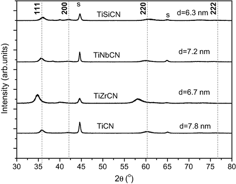
XRD spectra of the deposited films: s = substrate, d = grain size.
The grain size is also given and is calculated from the Scherrer equation, being in the range from 6.3 to 7.8 nm. After the incorporation of alloying elements into TiCN structure there was a slight decrease in grain size.
The Raman spectra are shown in Fig. 2. The spectrum recorded for TiCN reference coating presents the best resolved features, with four peaks at 252 cm−1, 346 cm−1, 565 cm−1, and 657 cm−1. These bands can be attributed to first-order Raman scattering by phonons, more precisely transverse acoustic (TA), longitudinal acoustic (LA), transverse optic (TO), and longitudinal optic (LO) modes (Escobar-Alarcón et al., 2010). For all of the doped coatings, the bands in the optical phonon range are not well separated, being broader than the reference TiCN sample. This is indicative of a lower crystal order in the doped samples. In the acoustic phonon range, the TO and LO bands are clear for the Nb and Si doped coatings and are similar to the TiCN coating.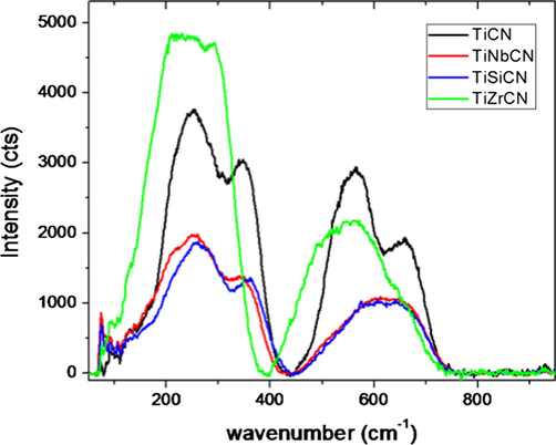
Raman spectra of the deposited films.
The TiZrCN spectrum deviates from this behaviour as the acoustic phono-region is not well defined. The ratio between the intensity of the acoustic phonon modes and that of the optical phonon modes is also considerably larger than that for the other samples. This suggests more disorder in this samples’ lattice. On the other hand, the samples did not exhibit any Raman bands above 800 cm−1, in the range where the so-called D and G bands would be expected for samples containing an amorphous carbon phase. This suggests that C atoms are linked in a TiCNX (with X being the dopant) lattice rather than forming C—C bonds in an amorphous phase. A good homogeneity of the films across the sample surfaces was observed, which was confirmed by the reproducibility of the spectra recorded from several regions on each sample.
The cross-sectional SEM micrographs of the coatings deposited on the Si wafers are illustrated in Fig. 3 (×50,000 mag.). The TiCN reference and the coatings with Zr and Nb additions exhibit columnar structures, with integer and fractured columns of different dimensions. An obvious finer and denser structure was observed for the Si containing coating.
SEM crosssection through the various coated surfaces.
3.2 Adhesion strength and stress level
For the investigated coatings, the values of critical loads were measured between 20 and 30 N (Fig. 4). The most significant result was that the addition of Zr and Nb led to an improvement in coating adhesion over the TiCN basic system. The experiments did not reveal significant differences between the adhesion of the TiZrCN and TiNbCN coatings. Poor adhesion was observed for the TiSiCN coatings (Lc = 20 N).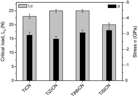
Adhesion critical load and macro strain of the deposited coatings.
Fig. 5 shows the SEM images of scratch tracks on the TiNbCN and TiSiCN coated samples, where the both cracking and coating breakthrough are visible. All samples examined displayed three of the coating failure types described by Larsson et al., semi-circular cracking, chipping, fracture and cohesive spallation along the scratch tracks. For the TiSiCN coating, discontinuous ductile perforation of the layer was seen (Fig. 5). For the TiCN and TiZrCN coatings, it was found that the size and severity of cohesive failures increased. A slightly lower Lc value was measured for the TiSiCN coating as a result of high higher stress level (Fig. 4).
SEM images of the scratch track for TiCN and TiSiCN coatings in the zone of the first crack (a and c) and the first coating breakthrough (b and d).
The residual stress ranged from −2.7 GPa to −3.2 GPa, indicating that all coatings exhibited a high compressive stress (Fig. 4). By adding Zr and Nb in TiCN structure, the residual stress was decreased, while the Si led to a higher stress. Low adhesion was found in the case of the highly stressed coatings (TiSiCN). The relatively good adhesion of TiZrCN and TiNbCN coatings to the substrate could be ascribed to the low residual stresses.
3.3 Electrochemical behaviour
The evolution of the open circuit potential during the 1 h immersion is given in Fig. 6, showing that all coated samples improved the corrosion resistance of the bare substrate. All coatings exhibited Eoc values that were more electropositive compared to the uncoated substrate. The open-circuit potentials of the coated test samples were stable for potentials in range of −150 mV to 40 mV, indicating good coating stability in 3.5% NaCl solution during 1 h immersion tests. The most noble open circuit potential was found for the TiNbCN coating (38 mV).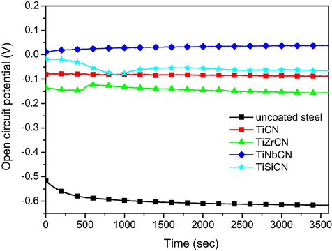
Open circuit curves of the uncoated and coated 316L stainless steel substrates.
The potentiodynamic polarization curves of the uncoated substrate and the coated specimens are shown in Fig. 7, while the electrochemical parameters are presented in Table 3. The corrosion resistance can be evaluated according to the following criteria:
Electro-positivity representing a resistance to corrosion: if the corrosion potential value is more electropositive, then the behaviour of the material is nobler in the used electrolyte. Fig. 7, shows that all coatings were nobler compared to the uncoated substrate. It was observed that:
-
–
the addition of Nb into the TiCN structure made corrosion potential more electropositive, indicating that the corrosive solution had less influence on the surfaces;
-
–
the most noble corrosion potential was measured with TiNbCN.
-
Materials with a low icorr value displayed a good corrosion resistance: all of the coatings with alloying elements showed lower icorr values compared to the uncoated substrate. TiNbCN coating exhibited a lower icorr value compared to all other samples, including the reference coating (TiCN).
Materials possessing superior anticorrosive properties present high Rp values. Considering the Rp values in Table 3, it can be observed that all coatings have higher polarization resistances than the substrate and the reference coating TiCN, except for the TiSiCN which showed the highest icorr value.
According to Mansfeld (1976), a material tends to passivate when the value of ba is greater than bc; conversely if ba is lower than bc, the material has a tendency to corrode (Liu et al., 2008). Most of the investigated coatings exhibited a tendency towards passivation. By contrast, the uncoated substrate had a low ba value, lower than bc, indicating a tendency to corrode.
Porosity of the coatings was also considered. Ahn et al. (2004) and Fedrizzi et al. (1994) reported that the porosity of deposited layers contributes to the corrosion behaviour of the coatings prepared by PVD methods. The total porosity (P) of the coatings was estimated using Elsener’s empirical equation (Eq. (2)), as it was reported in Elsener et al. (1989) and is shown in Table 3. The addition of Zr or Nb into the TiCN coating significantly decreased porosity leading to improved corrosion resistance. The TiNbCN coating exhibited the lowest porosity, followed by TiZrCN. The highest porosity value was determined for the TiSiCN coating, even when compared to the reference TiCN coating.
(2)where Rp,substrat and Rp,coating are the polarization resistance of the substrate and of the coating, respectively, ΔEi=0 – the difference between the corrosion potentials of the coatings and of the substrate, and ba is the anodic slope of the substrate.The protective efficiency (Pe) of the coatings was determined using Eq. (3) (Nozawa and Aramaki, 1999):
(3)where icorr,coating and icorr,substrate are the corrosion current densities of the coating and of the substrate, respectively.
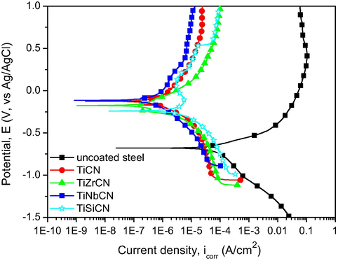
- Potentiodynamic polarization curves of the uncoated and coated 316L stainless steel substrates.
| Sample | Ei=0 (mV) | icorr (μA/cm2) | Rp (Ω) | ba (mV) | bc (mV) | P (×10−3) | Pe (%) |
|---|---|---|---|---|---|---|---|
| 316L steel | −679 | 74.478 | 568 | 134.1 | 354.8 | – | – |
| TiCN | −126 | 0.856 | 69,343 | 324.5 | 235.7 | 0.132 | 98.9 |
| TiZrCN | −175 | 1.563 | 105,096 | 969.3 | 619.2 | 0.126 | 97.9 |
| TiNbCN | −114 | 0.447 | 110,753 | 262.0 | 201.4 | 0.076 | 99.4 |
| TiSiCN | −240 | 6.944 | 12,442 | 857.4 | 258.7 | 1.730 | 90.7 |
Comparing the values in Table 3, it was observed that Pe increased with the addition of Nb as the alloying element. No significant differences in protective efficiency between the reference TiCN and the Zr and Nb alloyed coatings were found (<1%). All alloyed coatings had Pe values greater than 90%, offering a high protective efficiency.
Fig. 8 shows the SEM images of the surfaces at the end of the electrochemical tests, and there is an obvious difference between the corrosion resistances of the coatings. All of the coated surfaces present micro/macro particles, which were generated during the deposition process. Usually, these defects constitute preferential diffusion trails of aggressive species and can result in an accelerated coating failure. The reference coating was severely damaged during testing, while the alloyed coatings resisted NaCl corrosive attack.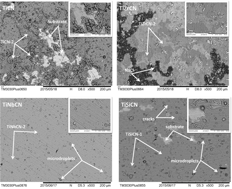
SEM images of all coatings at the end of the electrochemical tests at 500× and 2500× (inset pictures) magnifications.
After the corrosion attack, the samples were analysed for their elemental composition changes using EDS mapping on an area of 1280 × 1100 μm2. The elemental analyses on the investigated area of all the samples are given in Fig. 9, before and after corrosion tests. For the uncoated 316L stainless steel substrate, a high oxygen content was observed after the corrosion tests (26.1 ± 2.1 at.%), indicating that surface oxidation had occured during the test. An increase in oxygen content was observed for all coatings, but was the most pronounced for the TiZrCN coating. A relative decrease in the concentration of all other elements of the coatings was observed, due to the oxidation. Comparing the coatings, Fe content arising from the substrate was found in the case of TiCN, TiZrCN and TiSiCN, indicative of their poorer resistance to corrosive attack. A significant concentration of Fe was measured on the corroded surface of TiZrCN coatings (15.1 ± 0.9), as also can be seen on the SEM images after the electrochemical tests (Fig. 8). Also, some traces of Na and Cl were found on the uncoated substrate and TiZrCN coating. This is evidence of the electrolyte on the films, located most probably in the surface defects created by the corrosive attack.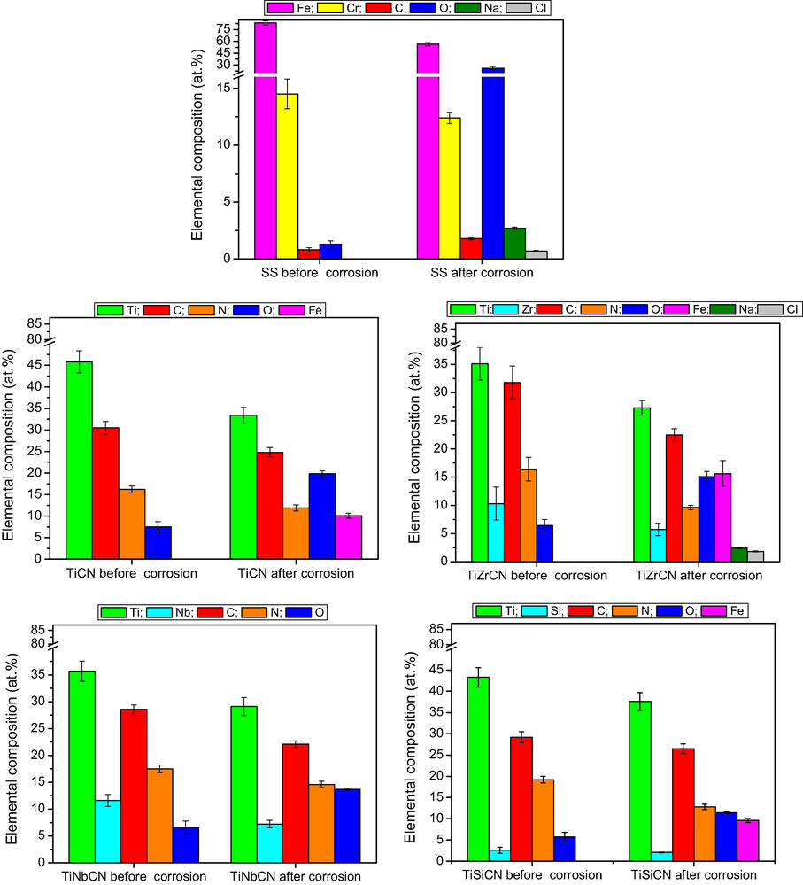
The elemental compositions before and after the electrochemical tests of the studied samples by EDS.
The TiZrCN coating was more affected by the electrochemical tests than the other coatings: clear dissolution of the coatings can be seen. On the TiSiCN surface, separate fragments of the coating and substrate were observed, demonstrating also a weak corrosion resistance in NaCl solution. The TiNbCN exhibited a low degree of localized corrosion, indicating that this coating offers the best protection for steel against an aggressive NaCl environment.
Similar results were found when inspecting the coatings at higher magnification (2500×). The surfaces of TiNbCN were similar before and after corrosion tests, indicating that the NaCl corrosive solution did not have any effect on this coating. For the TiSiCN coating, cracks and delamination of the coatings were observed on the surfaces after the electrochemical tests. All data from the SEM examinations are in line with the results derived from the analysis of the electrochemical parameters.
To summarize the results of the electrochemical tests, it can be concluded that the Zr, Nb or Si additions to TiCN coating led to a higher protection against corrosive attack in 3.5% NaCl. Of the investigated coatings, TiNbCN proved to be the most corrosive resistance, likely due to the high electronegativity of Nb.
3.4 Tribological performance
3.4.1 Friction performance
The results of the tribological tests were expressed in terms of the change of coefficient of friction (COF) versus time, and wear rate (K). Fig. 10a and b shows the evolution of the coefficients of friction as a function of time at room temperature (23 °C) and 250 °C.
Fig. 10a shows that at room temperature the friction coefficients for the coatings are approximately 3 times lower than those of uncoated samples, being stable at about 0.2. This is not the case at 250 °C. The TiZrCN coating has the highest coefficient of friction and is close to the COF of the uncoated material.
Fig. 11 shows the averages of the coefficients of friction at 23 °C and 250 °C. The average value was calculated after a ‘running period’ of 1000 s to eliminate initial contact instabilities. For the uncoated specimens the friction is lower at higher temperatures, which is most probably due to the formation of oxide layers on the sample surface which are known to induce a low friction coefficient (Polcar et al., 2006; Holmberg et al., 1998; Rester et al., 2006; Braic et al., 2014). In contrast, the coatings performed worse at 250 °C, where there was more severe film damage. This is consistent with previously reported data on friction performance of carbide or carbonitride coatings (Polcar et al., 2006; Rester et al., 2006; Braic et al., 2014).
3.4.2 Wear resistance
Fig. 12 shows the wear rate K, calculated post-testing. Wear rates in the coating specimens reduced compared with the uncoated specimens, suggesting a longer life than uncoated samples. For the alloyed coatings, the wear rates at 250 °C were higher than those measured at room temperature, likely as a result of a more intense oxidation process.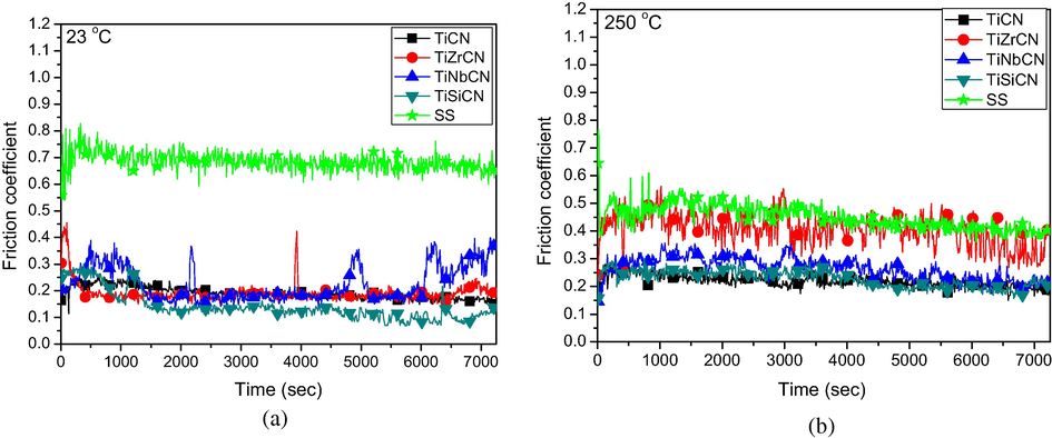
Evolution of the friction coefficients for coated samples vs. time at room temperature (a) and 250 °C (b).
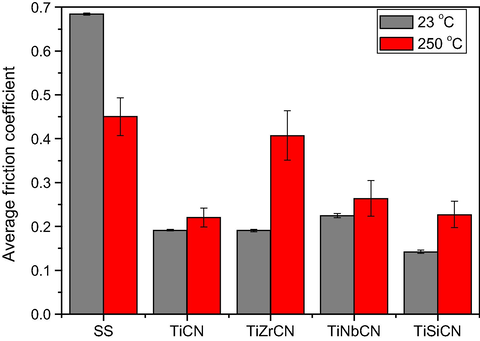
The average friction coefficients of the coatings at 23 °C and 250 °C.
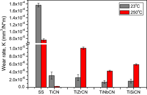
Wear rate for coated samples at 23 °C and 250 °C.
The optical micrographs and surface profiles of the wear tracks at the end of the sliding tests are shown in Figs. 13 and 14 and provide a map of the dominant wear mechanisms. The presence of grooves parallel to the sliding direction is indicative of the abrasive nature of the wear. The deepest wear tracks were found in the TiNbCN and TiSiCN coatings subjected to high temperature, while the largest width occurred on the TiZrCN surface also under the high temperature. A deeper wear scar and a larger track led to an increase in the friction coefficient confirmed by the results given in Figs. 10 and 11, which showed an increased friction coefficient for the coatings tested at 250 °C.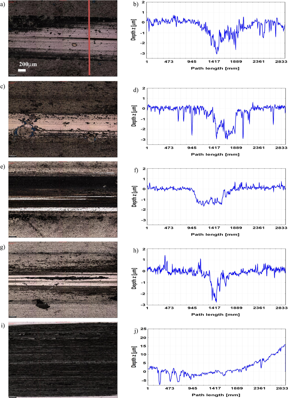
Optical images and cross-sectional wear profiles of the wear tracks for the coatings tested at 23 °C: TiCN (a and b), TiZrCN (c and d), TiNbCN (e and f), TiSiCN (g and h) and uncoated sample (i and j).
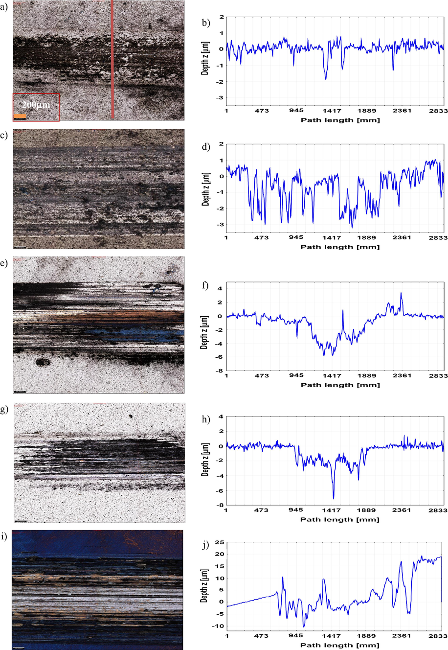
Optical images and cross-sectional wear profiles of the wear tracks for the coatings tested at 250 °C: TiCN (a and b), TiZrCN (c and d), TiNbCN (e and f), TiSiCN (g and h) and uncoated (i and j) sample.
Further details of the wear processes can be observed in Fig. 15, where the wear track morphology of an uncoated sample and the coatings tested at 23 °C and 250 °C are shown. This is compared to the morphology of selected samples, at high magnification, after the tribological tests in Fig. 16 of the bare substrate, TiNbCN tested at 23 °C and TiCN at 250 °C. For all the uncoated and coated samples, abrasive wear scars (groves of different widths parallel to sliding direction) are seen. On the uncoated 316L steel specimen, the formation of micro/macro pitting and craters, as well as debris fracturing, is visible, showing severe wear damage and a low wear resistance (Fig. 16a). In contrast, the coated samples were much less affected by wear (Fig. 16b and c). For these, beside the some minor abrasive wear, a mild polishing can be identified. Local failures in the TiCN coating can be also seen.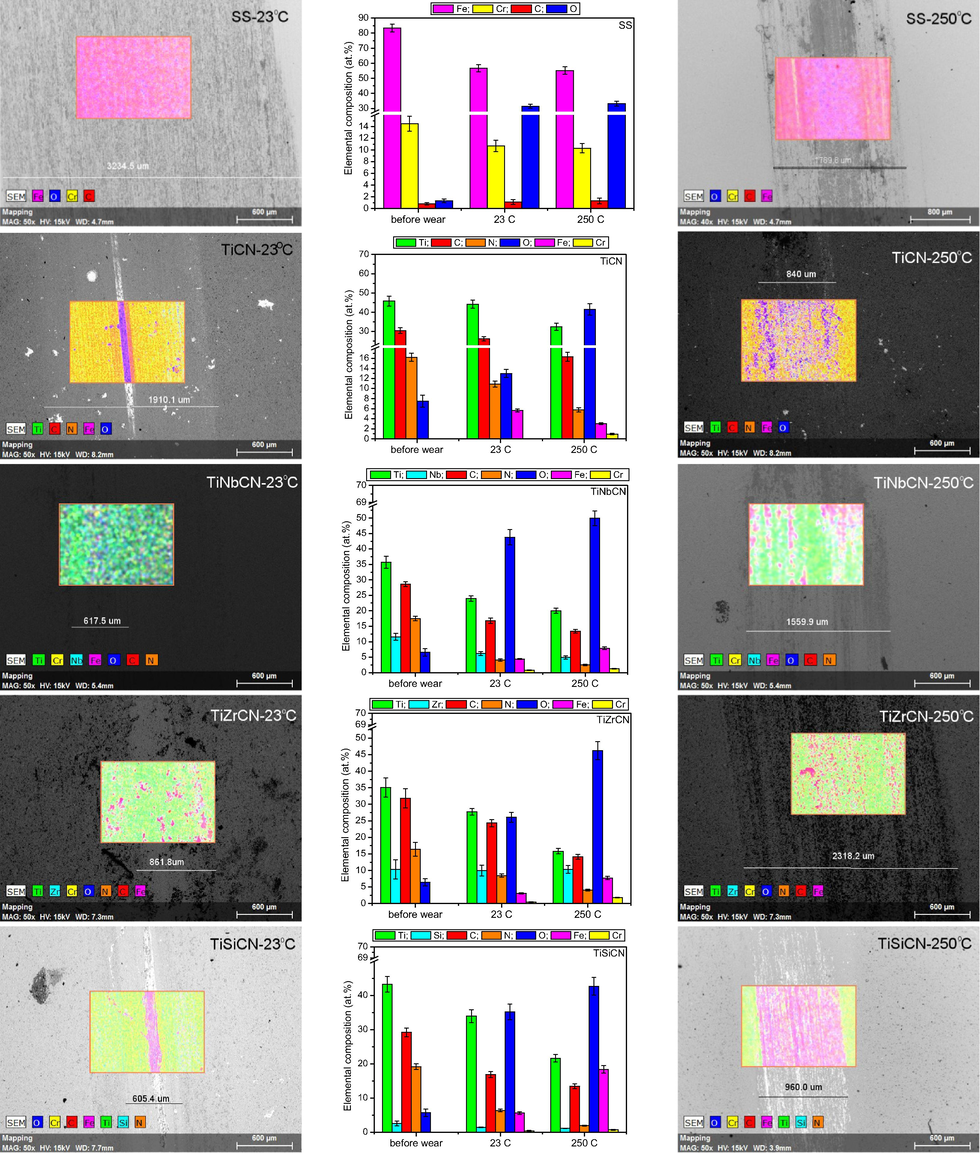
Surface morphology after tribological testing and the elemental compositions before and after wear testing of all of the investigated samples at 23 °C and 250 °C.
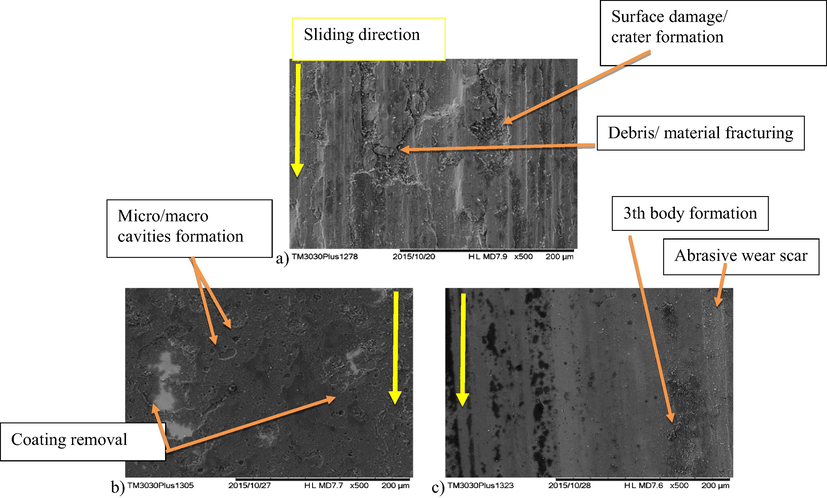
Surface morphology after tribological testing for (a) uncoated sample at 23 °C and selected coatings: (b) TiNbCN at 23 °C and (c) TiCN at 250 °C.
An elemental map, within the wear tracks of all of the samples tested at 23 °C and 250 °C is given in Fig. 15. For comparison, the results for an uncoated sample, as well as the atomic concentrations before wear testing, are also presented. For the uncoated specimen, a substantial percentage of oxygen (31.5–33.2 at.%) was detected after testing, suggesting that there was a major contribution from an oxidation phenomena to the wear mechanisms. This is also true in the case of the coated samples, for which there was a significant increase in oxygen content. Elemental concentrations differed from a zone to another one, indicating that the wear processes were not uniform across the worn surface. The EDS spectra (Fig. 15) revealed the presence of Fe within the substrate. This indicates a severe degradation of the coating, and is treated as an index for the severity of the wear damage. Moreover, the width of the wear track of the uncoated substrate was higher than that of the coatings, indicating that the tribological performance of the SS steel was significantly improved by coatings.
Summarizing the data from the optical, SEM and EDS analyses, the wear mechanisms present in the deposited coatings were a result of the combined effects of abrasive, oxidative and polishing wear.
4 Conclusions
TiCN, TiNbCN, TiZrCN, and TiSiCN coatings were prepared and investigated for elemental and phase composition, adhesion, anticorrosive properties and tribological performance at room and high temperatures. The following conclusions can be drawn from the study:
-
Zr, Nb and Si alloying elements in the film composition were in the range 2.9–9.6 at.%.
-
The coatings exhibited f.c.c. solid solutions and the (1 1 1) preferred orientation.
-
All the coatings had a good adhesion to the metallic substrate, critical loads of 20–30 N being measured. The best adhesion was found for the TiNbCN coating.
-
Ti based coatings with Nb or Si alloying elements proved to be resistant to corrosive attack in 3.5% NaCl. The TiNbCN coating was found to have the best corrosion resistance, due to the low residual stress and high adhesion to the substrate.
-
Coatings improved the friction coefficients across all experimental parameters.
-
The wear mechanism was found to be dominated by abrasive and oxidative processes.
-
The best wear resistance was measured in the TiCN coating at 250 °C and the TiNbCN coating at 23 °C.
Acknowledgments
This work was supported by a grant from the Romanian National Authority for Scientific Research, CNDI-UEFISCDI, project number PN-II-ID-PCE-2011-3-1016. The SEM microscope was acquired by the infrastructure project INOVA-OPTIMA SMIS code 49164, contract no. 658/2014. In the UK, Dr Pruncu was supported by KTP9299 (Innovate UK). The experimental equipment used in this research, within the Birmingham Centre for Cryogenic Energy Storage, was obtained with support from the Engineering and Physical Sciences Research Council, under the eight great technologies: energy storage theme (Grant number EP/L017725/1).
References
- A study on the quantitative determination of through-coating porosity in PVD-grown coatings. Appl. Surf. Sci.. 2004;233:105-114.
- [Google Scholar]
- Tool materials and surface treatments. J. Mater. Process. Technol.. 1992;35:515-528.
- [Google Scholar]
- Tribological properties of CrN coated H13 grade tool steel. J. Iron. Steel Res. Int.. 2014;21:240-245.
- [Google Scholar]
- Sliding wear of CrN, AlCrN and AlTiN coated AISI H13 hot work tool steels in aluminium extrusion. Tribol. Int.. 2013;57:101-106.
- [Google Scholar]
- Handbook of Vacuum Arc Science and Technology: Fundamentals and Applications. 1995.
- Effects of substrate temperature and carbon content on the structure and properties of (CrCuNbTiY)C multicomponent coatings. Surf. Coat. Technol.. 2014;258:996-1005.
- [Google Scholar]
- Cramer S.D., Covino B.S. Jr., eds. ASM Handbook Volume 13A: Corrosion: Fundamentals, Testing, and Protection. ASM International; 2003.
- Unlubricated friction and wear behaviors of ZrN coatings against hardened steel. Mater. Des.. 2008;29:1828-1834.
- [Google Scholar]
- Wear mechanisms of PVD ZrN coated tools in machining. Int. J. Refract. Met. Hard Mater.. 2008;26:164-172.
- [Google Scholar]
- Handbook of Vacuum Science and Technology. 1997.
- Impedance study on the corrosion of PVD and CVD titanium nitride coatings. Mater. Sci. Forum. 1989;44–45:29.
- [Google Scholar]
- The influence of alloying elements on the phase stability and mechanical properties of AlCrN coatings. Surf. Coat. Technol.. 2005;200:988-992.
- [Google Scholar]
- TiCN thin films grown by reactive crossed beam pulsed laser deposition. Appl. Phys. A. 2010;101:771-775.
- [Google Scholar]
- Effects of Co and W alloying elements on the electrodeposition aspects and properties of nanocrystalline Ni alloy coatings. Appl. Surf. Sci.. 2011;257:5919-5926.
- [Google Scholar]
- Corrosion protection of sintered metal parts by coating deposition. Part I: Microstructural characterization. Mater. Corros.. 1994;45:222-231.
- [Google Scholar]
- Comparison of the corrosion of bulk amorphous steel with conventional steel. Corros. Sci.. 2010;52:273-281.
- [Google Scholar]
- From alloying to nanocomposites – improved performance of hard coatings. Adv. Eng. Mater.. 2000;2:247-259.
- [Google Scholar]
- Corrosion behavior of a Zr-base bulk glassy alloy and its crystallized counterparts. Mater. Trans.. 2001;42:1109-1111.
- [Google Scholar]
- Coatings tribology—contact mechanisms and surface design. Tribol. Int.. 1998;31:107-120.
- [Google Scholar]
- The effect of relative humidity on wear of a diamond-like carbon coating. Surf. Coat. Technol.. 2003;167:221-225.
- [Google Scholar]
- Performance of PVD TiN, TiCN, and TiAlN coated cemented carbide tools in turning. Int. J. Refract. Met. Hard Mater.. 1999;17:163-170.
- [Google Scholar]
- Multifunctional multi-component PVD coatings for cutting tools. Surf. Coat. Technol.. 2005;200:1867-1871.
- [Google Scholar]
- Wear mechanisms and tool performance of TiAlN PVD coated inserts during machining of AISI 4140 steel. Wear. 2007;262:64-69.
- [Google Scholar]
- Wear of advanced cemented carbides for metal forming tool materials. Wear. 2004;256:846-853.
- [Google Scholar]
- Critical review on the elastic properties of transition metal carbides, nitrides and carbonitrides. J. Alloys Compd.. 1998;265:215-233.
- [Google Scholar]
- Comparison of TiAlN, AlCrN, and AlCrN/TiAlN coatings for cutting-tool applications. Int. J. Miner. Metall. Mater.. 2014;21:796-805.
- [Google Scholar]
- Comparative study of Ti1−xAlxN coatings alloyed with Hf, Nb, and B. Surf. Coat. Technol.. 2005;200:113-117.
- [Google Scholar]
- Solid state properties of group IVb carbonitrides. J. Alloys Compd.. 1995;217:137-147.
- [Google Scholar]
- Microstructure, hardness and corrosion resistance of ZrN films prepared by inductively coupled plasma enhanced RF magnetron sputtering. Plasma Sci. Technol. 2008;10:170-175.
- [Google Scholar]
- The Polarization Resistance Technique for Measuring Corrosion Currents. Vol vol. 6. US: Springer; 1976.
- Tool steel coatings based on niobium carbide and carbonitride compounds. Surf. Coat. Technol.. 2012;207:472-479.
- [Google Scholar]
- PVD and CVD coating systems on oxide tool ceramics. J. Achiev. Mater. Manuf. Eng.. 2007;24:75-78.
- [Google Scholar]
- One- and two-dimensional polymer films of modified alkane thiol monolayers for preventing iron from corrosion. Corros. Sci.. 1999;41:57.
- [Google Scholar]
- The tribological characteristics of TiCN coating at elevated temperatures. Wear. 2006;260:40-49.
- [Google Scholar]
- Effects of carbon content on the high temperature friction and wear of chromium carbonitride coatings. Tribol. Int.. 2010;43:1228-1233.
- [Google Scholar]
- State of the art in hard coatings for carbide cutting tools. Surf. Coat. Technol.. 1998;102:183-190.
- [Google Scholar]
- Annealing studies of nanocomposite Ti-Si-C thin films with respect to phase stability and tribological performance. Mater. Sci. Eng., A. 2006;429:90-95.
- [Google Scholar]
- Estimation of corrosion current by the analysis of polarization curves: electrochemical kinetics mode. Russ. J. Electrochem.. 2014;50:108-113.
- [Google Scholar]
- On the determination of film stress from substrate bending: STONEY’s formula and its limits. Whitepaper. 2006;52:1-17.
- [Google Scholar]
- Corrosion and related mechanical properties of bulk metallic glasses. J. Mater. Res.. 2007;22:302-313.
- [Google Scholar]
- Performance of CrN radical nitrided tools on deep drawing of advanced high strength steel. Surf. Coat. Technol.. 2011;205:4198-4204.
- [Google Scholar]
- Electrochemical polarization: I. A theoretical analysis of the shape of polarization curves. J. Electrochem. Soc.. 1957;104:56.
- [Google Scholar]
- Electrochemical polarization I. A theoretical analysis of the shape of polarization curves. J. Electrochem. Soc.. 1957;104:56-63.
- [Google Scholar]
- New theories of wear and their implications for tool materials. Wear. 1980;62:1-20.
- [Google Scholar]
- Transition Metal Carbides and Nitrides. New York: Academic Press; 1971.
- State of the art for the industrial use of ceramic PVD coatings. Surf. Coat. Technol.. 1995;74:629-633.
- [Google Scholar]
- Understanding corrosion via corrosion product characterization: II. Role of alloying elements in improving the corrosion resistance of Zn-Al-Mg coatings on steel. Corros. Sci.. 2011;53:2437-2445.
- [Google Scholar]
- TiN coating of tool steels: a review. J. Mater. Process. Technol.. 1993;39:165-177.
- [Google Scholar]


