

Translate this page into:
Combustion customization strategy of mixed propellant charges for multi-material additive manufacturing: Simulation and experiment
⁎Corresponding author at: School of Chemistry and Chemical Engineering, Nanjing University of Science and Technology, Nanjing 210094, China. hewedong@njust.edu.cn (Weidong He)
-
Received: ,
Accepted: ,
This article was originally published by Elsevier and was migrated to Scientific Scholar after the change of Publisher.
Peer review under responsibility of King Saud University.
Abstract
This paper addressed three major challenges in the customization of mixed propellant charges: optimal design, performance simulation, and manufacturing. Based on parametric modeling software Grasshopper, parametric models of propellants with highly complex geometries were endowed with combustion properties of multiple formulations, coupled with rapidly changing burning rate-pressure field during iterative combustion to achieve visual and integrated simulation of burning surface regression, form function, and combustion performance of mixed charges, providing convenient theoretical guidance for structural optimization design of customized strategies. Customized zones designed with complex geometries and multiple formulations co-constructed in one propellant were prepared by multi-material additive manufacturing techniques. Different customized zones of one or more propellants were superimposed in the design sequence to customize the combustion performance. Mixed charges for three cases of burning surface, burning rate, and joint control were discussed. The simulation results matched well with the experimental results, including the progressively random perforated combustion, variation of burning rate pressure exponent, and superimposed combustion of single and multiple charges with different customized zones. As an advanced engineering strategy urgently needed in chemical engineering, this work not only opens the door to matching performance simulation-driven design with MM-AM technologies but also serves as an efficient and common customization strategy from design to manufacture.
Keywords
Mixed propellant charges
Complex structure
Integrated simulation
Grasshopper
Multi-material additive manufacturing
Combustion performance

Nomenclature
- 2e1, 2e
-
Initial web thickness and burned web thickness of mixed charges
- M1, MY, M
-
Initial mass, burned mass, and instantaneous mass of mixed charges
- wi, mi, mYi
-
Mass percentage, instantaneous mass, and burned mass of the ith propellant in mixed charges
- 2ei, v1i, vi
-
Burned web thickness, initial volume, and instantaneous volume of the individual grain of the ith propellant in mixed charges
- Z, Ψ
-
Web thickness fraction, and burned mass fraction of mixed charges
- t, p, pm, pb, Δ
-
Combustion time, combustion pressure, maximum pressure, ignition pressure, and loading density of mixed charges
- 2eR, uR(p)
-
Burned web thickness and burning rate of the reference propellant in mixed charges
- fMC, Ki
-
Force constant, and burning rate ratio of mixed charges
- fi, ui(p), μ1i, ni
-
Force constant, burning rate, burning rate coefficient, and burning rate pressure exponent of the ith propellant in mixed charges
- ρ, α
-
Density and co-volume of the propellant
- O, d0, 2e0, D0, H0
-
Geometric parameters, initial inner diameter, initial web thickness, initial outer diameter, and initial height in the parametric model of the propellant
1 Introduction
The propellant, as a chemical product, is the source of energy for weapon launch systems. In recent years, the rapid development of modern weapon systems towards long-range and high power has placed higher demands on the control of combustion processes for propellants (Luman et al., 2007; Chen et al., 2022). Therefore, the customization of propellant combustion performance is an advanced engineering strategy to meet the urgent requirements of modern chemical engineering.
It is well known that the combustion performance of propellants is mainly controlled by the burning surface and burning rate, which depend on the geometry and formulation of the propellant, respectively (Wurster, 2017; Jie-Yao et al., 2022). In order to control the combustion performance more effectively, mixed propellant charges consisting of two or more different types (geometry and formulation) of propellants have been developed (Fu et al., 2021). Actually, the geometry of propellants is significantly hindered by conventional manufacturing technologies and is generally relatively simple (Rahimi et al., 2010; Yang et al., 2020a). Hence, the current range of burning surfaces available for adjustment of the mixed charges is limited. In addition, propellants of different formulations in mixed charge usually burn together, making it difficult to flexibly control the burning rate change in the combustion process (Xu and He, 2017; Yang et al., 2020b). Therefore, it is still a great challenge to customize the combustion performance for current mixed charges.
With the booming development of additive manufacturing (AM), the first steps are being taken in the field of energetic materials (Muravyev et al., 2019; Zhang et al., 2022). AM technologies such as photocuring (Straathof et al., 2019; Li et al., 2021), material extrusion (Chandru et al., 2018; Wang et al., 2022a), and laminated object manufacturing (LOM) (Wang et al., 2022b) have been used for the preparation of single-formulation propellants. Multi-material additive manufacturing (MM-AM) allows not only the easy fabrication of complex geometries but also the precise control of material properties at different locations to achieve complex structures with specific functional zones (Bandyopadhyay and Heer, 2018; Yuan et al., 2020; Gu et al., 2021). The MM-AM enables the preparation of a new generation of mixed charges with different customized zones of combustion performance that are jointly controlled by complex geometry and multi-formulation.
Unfortunately, the simulation of the combustion performance of mixed charges has not been matched with the development of manufacturing technology for a long time, which is another obstacle to customized strategy in theoretical exploration. The design and optimization of mixed charges still need to be guided by extensive experiments (Jiang et al., 2021), rather than simulations. In mixed charges, there are many charge parameters to be determined, such as the geometry, size, formulation, mass percentages of each charge, etc., which leads to expensive and time-consuming experiments (Xu and He, 2017; Yang et al., 2020). Because of this, the interaction of various factors makes the combustion process of mixed charges dramatically complicated. Several methods have been investigated to simulate the combustion performance of a single charge, such as analytical, numerical, and solid modeling methods. Due to the complexity and difficulty of establishing mathematical expressions for complex surfaces, the analytical method usually calculates the simplified geometry (Yang et al., 2021). The simplified geometry is not enough to represent the actual combustion process of the propellant, not to mention ignoring the dramatic effect of different formulations on the burning rate as a function of pressure (Zhang et al., 2019; Yao et al., 2021). The numerical and solid modeling methods are theoretically applicable to arbitrarily complex geometries. Numerical methods usually use interface tracing methods (Level Set and Minimum Distance Function, etc.) to transform geometric problems into purely mathematical ones (Xiao et al., 2016; Ki et al., 2017; Oh et al., 2020). This method is computationally intensive and the results are sensitive to the mesh quality and the burning rate-pressure field of the discrete geometry (Wei et al., 2018; REN et al., 2021). The numerical dissipation is more severe for complex structures (Hwang and Chiang, 2015). The solid modeling method based on computer-aided design (CAD) software is able to visualize the burning surface changes of propellant and output the geometric configuration data (Rafique et al., 2015). However, the reported methods based on CAD software such as UG, SolidWorks, and Pro/E have to be developed secondarily using other programming languages, due to their limitations (Wang et al., 2004; Xiong et al., 2008). In our previous study, based on Grasshopper (GH) software, a kind of parametric modeling software with visual programming, the form function calculation and geometric optimization design of complex geometric propellants were conveniently and efficiently realized (Wang et al., 2022c). The main challenge for mixed charge combustion performance simulation is the coupling between complex geometries and different formulations of propellants and their co-constructed complex burning rate-pressure fields. Therefore, how to simulate the combustion performance of mixed charges with high accuracy and high efficiency has always been a tricky problem faced by the industry.
This paper addressed three major challenges in the customization of mixed propellant charges: optimal design, performance simulation, and manufacturing. Propellant parametric models with highly complex geometries were zoned to endow multiple materials with combustion properties based on GH software. And the coupling of parametric models with the rapidly changing burning rate-pressure field was multi-iterated. Through visual scripts, the integrated simulation of burning surface regression, form function calculation, and combustion performance prediction of mixed charges with complex structures (geometry and multi-formulation) provided theoretical guidance for structural optimization design and analysis of customized strategies. Integrated simulations and experiments on the combustion performance of three mixed charges with respect to the burning surface, burning rate, and their joint control were discussed. The first two were manufactured by conventional processes, while the last was a new generation of mixed charges with different customized zones of combustion performance in propellant proposed and prepared based on MM-AM. This work aims to fill the gap in mixed charge combustion performance simulation and open the door to combustion performance customization, hopefully as a common customization strategy.
2 Integrated simulation
Grasshopper (GH) is a parametric modeling software running on the CAD software Rhinoceros, widely used in the field of architectural design. It visualizes the data operation process with node types (Bertacchini et al., 2021; Vantyghem et al., 2021). “Components” and “lines” form programs with certain functions without writing conventional scripts, which greatly reduces programming requirements and improves programming efficiency (Qi et al., 2021). The created program can be saved as a custom component for permanent use.
The combustion process of propellants follows the “geometric combustion law”, that is, it is assumed that the geometry and size of all propellants are consistent and all surfaces burn along the normal direction at the same time (Bougamra and Lu, 2015). Therefore, the propellants’ combustion process is represented by a propellant grain. The basic idea of using GH software to simulate the combustion performance of mixed charges was as follows: Parametric models with combustion properties (force constant and burning rate) were developed from the different propellant formulations. The coupling of parametric models with the rapidly changing burning rate-pressure field during the combustion process was multi-iterated so that the dimensional parameters of the parametric models change independently with the advance of the combustion process. The burning surface regression of the mixed charges was displayed in real-time, while relevant parameters of parametric models were captured to complete the output of the form function (Ψ = f(Z)) and combustion performance (p = f(t)) of the mixed charges. The simulation method allows efficient integration of visual burning surface regression, form function calculation, and combustion performance prediction. The algorithm flow and visualization program of the integrated simulation of mixed charges were shown in Fig. 1, including four modules: parametric modeling, form function calculation, combustion performance prediction, and combustion driving.
(a) The algorithm flow of the integrated simulation. (b), (c), (d) The visualization program of the integrated simulation.
Parametric modeling is the use of programs to generate numerous model families with highly complex geometry that meet the rules (Touloupaki and Theodosiou, 2017). The geometric parameters can be changed dynamically to change the geometry and dimension of the model, thus realizing the parameterization of the model. The parametric modeling was detailed in our previous study (Wang et al., 2022c).
The visualization program of the form function calculation module was shown in Fig. 1b. In mixed charges, the sum of the mass percentages of each propellant is 100 wt%. When there is only one propellant, the calculation is made for that single charge with a mass percentage of 100 wt%. The propellant that finally burned out during combustion was defined as the reference propellant for mixed charges. The burned web thickness and the web thickness at the end of combustion of the reference propellant were defined as the burned web thickness (e) and the initial web thickness (e1) of mixed charges, respectively. The instantaneous volume (vi) of propellants with complex geometry could be obtained from parametric models. The integral form function of the mixed charges and the form functions of each propellant were calculated according to the equations below.
The combustion performance prediction module is the most important part of the integrated simulation, and the visualization program is shown in Fig. 1c. The combustion process of propellants will produce a sharp change of high pressure, in turn, the change of pressure will affect the combustion progress. The pressure of the mixed charges (p) was generated by the co-combustion of all propellants and was expressed by the Noble-Abel equation (Leciejewski and Surma, 2019). The combustion properties (force constant and burning rate) are different for different propellant formulations. The force constant represents the energy property of the propellant, which describes the power capability (Boulkadid et al., 2020). The force constant of the mixed charges (fMC) was variable during combustion and depended on the force constant and combustion progress of each propellant in mixed charges, which was defined in the following equation. The burning rate of different propellant formulations (ui) is described by Vieille Law, which varies independently with p (Damse et al., 2007; Leciejewski, 2008). Taking the burning rate of the reference propellant as the benchmark, the ratio between the burning rate of each propellant and the reference propellant was defined as the burning rate ratio (Ki). Ki also varies independently with p during the combustion of mixed charges. The combustion properties of different propellant formulations were assigned to the different zones of parametric models, coupled with the rapidly changing burning rate-pressure field during iterative combustion to predict the combustion performance of mixed charges.
The visualization program of the combustion driving module was seen in Fig. 1d. In the parametric model, the initial burning surface of the propellant was defined at e = 0. With the increase of e, the propellant geometry and instantaneous volume (vi) can be dynamically displayed and obtained in real-time until the end of combustion. The time when the combustion of the reference propellant ended was defined as the combustion time of the mixed charges (t). At the same time, the burned web thickness of each propellant (ei) in mixed charges depended on its burning rate (ui(p)). The Loop component in GH software was used to independently drive t and ei. The step size was chosen to be 0.01 mm as our previous study found that this step size has adequate accuracy to meet the needs (Wang et al., 2022c).
The integrated simulation method not only visually fills the gap of mixed charges combustion performance simulation, but also flexibly applies to mixed charges with complex geometry and multiple formulations, which provides theoretical guidance for the design, analysis and optimization of mixed charges based on multi-material additive manufacturing.
3 Experiment
3.1 Materials and methods
For the mixed charges controlled by burning surface and burning rate respectively, coated propellant and variable burning rate pressure exponent propellant were selected, both of which are typical charges prepared by the conventional process (Sanghavi et al., 2007). The coated propellant mixed charges (1#) consisted of two different geometries of rosette-shaped 37-perf propellants (R37P) and rosette-shaped 19-perf coated propellants (R19CP), both prepared from the three-base formulation (TBF). The variable burn rate pressure exponent propellant mixture charges (2#) consisted of rose-shaped 19-perf geometry prepared in two formulations, NC-NG-DEGDN (MNEF) and RDX-NC-NG-DEGDN (RMNEF). The formulation composition and theoretical force constant were given in Table 1.
Based on multi-material additive manufacturing technology (MM-AM), a new generation of mixed charges with different customized zones of combustion performance in propellant was proposed. Currently, five of the seven generic additive manufacturing technologies specified in ASTM show the feasibility of MM-AM, including binder jetting, material jetting, material extrusion, directed energy deposition, and sheet lamination (Bandyopadhyay and Heer, 2018). In this paper, a new generation of mixed charges named shell-deterrent propellant (SDP) was introduced and manufactured using laminated solid manufacturing (LOM) technology. SDP (3#) consisted of the cylindrical shell and 7-perf propellants. The double-base formulation (DBF) and single-base formulation (SBF) were used, respectively, as listed in Table 1. The LOM printing process of propellants includes six steps: feeding, cutting, spraying, lamination, exposure, and removal, as detailed in our previous study (Wang et al., 2022b). The LOM printing process of SDP was schematically seen in Fig. 2a. First, the cylindrical shell propellant was printed, then 7-perf propellants were automatically loaded into the shell propellant, and finally the cap was printed to make it complete. The printed SDPs with different dimensions were shown in Fig. 2b. They have increasing shell thickness and height from left to right, forming the SDP mixed charges (4#).
(a) Schematic diagram of the printing process for laminated object manufacturing of shell-deterrent propellant, (b) Printed shell-deterrent propellants.
Names
NC
NG
NQ
DEGEN
RDX
Others
f
/ wt.%
/ wt.%
/ wt.%
/ wt.%
/ wt.%
/ wt.%
/ kJ·kg−1
TBF
28.0
22.5
47.0
\
\
2.5
1066
MNEF
53.7
29.9
\
14.7
\
1.7
1166
RMNEF
45.6
25.4
\
12.5
15.0
1.5
1199
DBF
58.5
40.0
\
\
\
1.5
1151
SBF
95.6
\
\
\
\
4.4
1012
TBF, MNEF, RMNEF, DBF, and SBF represent the propellant formulation names, which are respectively three-base formulation, NC-NG-DEGDN formulation, RDX-NC-NG-DEGDN formulation, double-base formulation, and single-base formulation. f represents the theoretical force constant of the propellant formulation. NC, NG, NQ, DEGEN, and RDX represent the propellant formulation compositions, which are nitrocellulose, nitroglycerine, nitroguanidine, diethylene glycol dinitrate, and cyclotrimethylene trinitramine, respectively.
3.2 Combustion performance test
The closed vessel test is an essential method to study the combustion performances of propellants and the interior ballistic performance of weapons, which provides a combustion environment under high pressure (Boulkadid et al., 2020), as shown in Fig. 3. The coated propellant mixed charges and the respective propellants (1#, R37P, R19CP) were ignited at 20 °C with Δ of 0.2 g·cm−3. The variable burning rate pressure exponent propellant mixed charges and the respective propellants (2#, R-MNEP, MNEP) were ignited at 20 °C with Δ of 0.2 g·cm−3. SDP (3#) and SDP mixed charges (4#) were ignited at 20 °C with Δ of 0.14 g·cm−3 and 0.22 g·cm−3, respectively.
The schematic diagram of the closed vessel test.
The dynamic vivacity curve (L-B curve) of propellants burning in the closed vessel can be obtained. The relative pressure (B) represents the burning process of propellants. The dynamic vivacity (L) reflects the comprehensive effect of geometry and formulation on the burning process of propellants (Naya and Kohga, 2014). Their definitions were as follows (Pauly and Scheibel, 2010; Tırak et al., 2019). Comparing the theoretical L-B curve obtained from the integrated simulation with the test L-B curve obtained from the closed vessel test, not only can the accuracy of the simulation be verified, but also the actual combustion process can be analyzed to guide the design and optimization of mixed charges.
4 Results and discussion
4.1 Coated propellant mixed charges
Coated propellant mixed charges occupy an important position in the current mixed charges controlled by the burning surface. The presence of the coated layer structure can serve to reduce the initial gas generation rate of propellants. However, the non-uniform coating thickness in the conventional process would lead to the randomness and non-simultaneity of the perforation combustion process of coated multi-perforation propellants (Xiao et al., 2014). In the integrated simulation, the coated propellant parametric model was easily developed. It is based on the multi-perforation propellant parametric model with the addition of coated layer and progressively random perforated combustion. Likewise, the coated propellant parametric model is a family of models containing coated 7-perf, coated rosette-shaped 37-perf, etc. The parametric modeling of the multi-perforation propellant was detailed in our previous study (Wang et al., 2022c).
The coated propellant mixed charges (1#) were composed of 70 wt% R37P (1#-0) and 30 wt% R19CP (1#-1), and the charge parameters were listed in Table 2. 1#-1 was the reference propellant for 1#. The burning surface regression simulation of R19CP was seen in Fig. 4a. The L-B curves of R37P, R19CP, and 1# were displayed in Fig. 4b, including the test curves obtained from the closed vessel test and the theory curves from the integrated simulation. It can be seen that test curves basically match theoretical curves. In detail, test curves generally dropped slightly earlier and slower than theoretical curves in the late stage of combustion, which was caused by the fact that the geometry and size (web thickness, diameter, and height) of all propellant grains cannot be guaranteed to be exactly the same during the manufacturing process, as well as the ignition of propellant grains was a gradual process (Gao et al., 2021). As the R19CP (coated propellants) added two stages of coated layer combustion and random burning perforations in the early combustion stage, the decline of the test curve in the late combustion stage was advanced. The addition of R37P in 1# significantly increased the gas generation rate at the early stage of combustion, resulting in improved consistency of R19CP perforated combustion, and reduced the difference between the test curve and the theoretical curve at the late stage of co-combustion.
NO.
Formulations
O
d0
2e0
D0
H0
wi
μ1
n
/ mm
/ mm
/ mm
/ mm
/ wt.%
/ mm·s−1·MPa-n
\
1#-0
TBF
R37
0.63
2.30
22.81
25.35
70
2.04
0.81
1#-1
TBF
R19C
0.48
2.30
16.20
17.80
30
2.04
0.81
Closed vessel test and integrated simulation results of coated propellant mixed charges. (a) The burning surface regression simulation of rosette-shaped 19-perf coated propellant (R19CP), (b) Test and theory L-B curves for rosette-shaped 37-perf propellants (R37P), R19CP and their composition of coated propellant mixed charges (1#).
Therefore, the gradual random perforations combustion process of coated propellant was visually and accurately simulated. Integrated simulation can effectively predict, analyze and guide the combustion performance of coated propellant mixed charges with different charge parameters in a high-pressure environment, making up for the current situation of relying heavily on closed vessel tests.
4.2 Variable burning rate pressure exponent propellant mixed charges
A propellant controlled by burning rate was recently reported in which the presence of RDX in the formulation varied the burning rate pressure exponent at different pressure stages (Fu et al., 2021). The reported combustion performance of their mixed charges was still determined by extensive closed vessel tests. 50 wt% RMNEP (2#-0) and 50 wt% MNEP (2#-1) made up the variable burning rate pressure exponent propellant mixed charges (2#), and the charge parameters were shown in Table 3. In the integrated simulation, 2#-0 was the reference propellant for 2#. The burning rate coefficients and pressure exponents of different stages were assigned to the parametric model of RMNEP (variable burning rate pressure exponent propellant). In addition, the formulations used to prepare RMNEP and MNEP differed, as did their combustion properties (force constants and burning rates).
NO.
Formulations
O
d0
2e0
D0
H0
wi
μ1
n
/ mm
/ mm
/ mm
/ mm
/ wt.%
/ mm·s−1·MPa-n
\
2#-0
RMNEF
R19
0.5
2.1
15.1
15.7
50
0.53
1.20
6.93
0.65
2#-1
MNEF
R19
0.5
2.1
15.1
15.7
50
1.75
0.90
The burning surface regression simulation of 2# was seen in Fig. 5a. The combustion process of RMNEP and MNEP in the mixed charge was visualized. In the figure, the different stages of RMNEP and MNEP were colored differently, representing the different combustion properties assigned to them. The test and theory L-B curves for RMNEP, MNEP, and 2# were plotted in Fig. 5b, obtained from closed vessel tests and integrated simulations, respectively. As can be seen from the figure, the theoretical and experimental curves were in good agreement. This showed that the combustion performance of variable burning rate pressure exponent propellants and their mixed charges were effortlessly simulated. The theory L-B curve of RMNEP started with low dynamic activity and then appeared with a plateau-like effect, which was consistent with the test curve. The combustion simulation of RMNEP at different pressure stages demonstrated that this integrated simulation method allowed convenient prediction of cases with different combustion characteristics in one propellant by the same parametric model. The general agreement between the theoretical and experimental curves of the mixed charges indicated that the co-combustion process of multiple propellants with different combustion characteristics coupled with pressure can be predicted conveniently and accurately.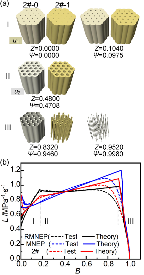
Closed vessel test and integrated simulation results of variable burning rate pressure exponent propellant mixed charges. (a) The burning surface regression simulation of variable burning rate pressure exponent propellant mixed charges (2#), (b) Test and theory L-B curves for RMNEP, MNEP, and 2#.
Whether burning surface control or burning rate control, the integrated simulation can be used as an efficient and common method to fill the gap in the current combustion performance simulation of mixed charges. This provides a solid foundation for designing and customizing mixed charges with complex structures and multiple materials through MM-AM.
4.3 Shell-deterrent propellant
Based on MM-AM, a new generation of mixed charges was proposed, defined as one propellant consisting of different customized zones of combustion performance. The customized zone was made up of complex geometries and multiple formulations. On the one hand, the respective control advantages of the burning surface and burning rate can be fully utilized in one propellant, and the control range of both of them is no longer limited by the conventional process. On the other hand, the advantages of the combined control of the two are not only simple summation, but the different customized zones can be superimposed to burn in the designed sequence.
As a new generation of mixed charges, a class of shells and their internal successive combustion of shell-deterrent propellant (SDP) was introduced. By adjusting the formulation and geometry of the shell propellant and the propellant inside the shell, the burning rate and the burning surface of the SDP can be controlled simultaneously, to realize flexible and controllable combustion performance. An SDP (3#) was printed using the LOM printing process, consisting of cylindrical shell double-base propellant (3#-0) and 7-perf single-base propellants (3#-1). The charge parameters were listed in Table 4. 3#-0 and 3#-1 not only had different formulations and geometries but also burned in a certain order. On the one hand, they burned independently according to their geometries and combustion properties, and on the other hand, they interacted with each other due to being under the same combustion pressure. 3#-0 was the reference propellant for 3#.
NO.
Formulations
O
d0
2e0
D0
H0
wi
μ1
n
/ mm
/ mm
/ mm
/ mm
/ wt.%
/ mm·s−1·MPa-n
\
3#-0
DBF
\
15.6
1.2
19.2
22.4
48.5
1.55
0.92
3#-1
SBF
7
0.2
0.5
2.6
2.4
51.5
1.79
0.87
Closed vessel test and integrated simulation results of 3# were shown in Fig. 6, including burning surface regression simulation (Fig. 6a), integral and respective form functions (Fig. 6b), test and theory L-B curves (Fig. 6c). As can be seen from the figure, the four stages of the SDP combustion process were clearly demonstrated and simulated. There was no significant difference between the experimental and theoretical L-B curves.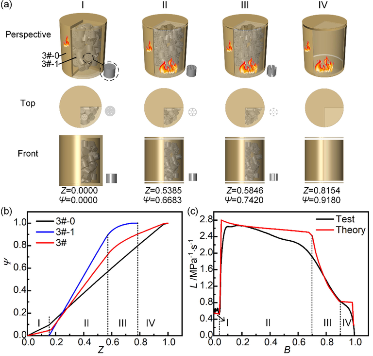
Closed vessel test and integrated simulation results of shell-deterrent propellant. (a) Burning surface regression simulation, (b) Integral and respective form functions, (c) Test and theory L-B curves.
The first stage was the combustion of 3#-0. Ψ increased slowly with Z. L-B curves were relatively low and remained almost constant. This indicated that SDP had a role in maintaining a low initial gas generation rate.
The second stage was the slivering behavior of 3#-0 and the beginning of combustion of 3#-1. When 3#-0 showed slivering behavior, the inner surface of the shell propellant also began to burn. All charges were exposed to the same combustion environment. Since the combustion of 3#-1 greatly increased the gas generation rate of SDP, the increasing trend of Ψ with Z was significantly greater than that of the first stage, and the L-B curves also increased sharply. Due to the combustion regressivity of 3#-0 and its nearly half mass percentage, the theoretical L-B curve showed a slightly decreasing trend. Similarly to the above, the ignition process of 3#-1 grains was not instantaneous, resulting in a slightly smaller rise and a slightly earlier and slower fall of the test L-B curve than the theory curve. The gas generation rate at this stage can be controlled by changing the mass percentage and combustion progressivity of the SDP internal charge, etc.
In the third stage, 3#-0 continued to burn and the slivering behavior of 3#-1 began until its burning ended. The increasing trend of Ψ with Z was smaller than that in the second stage, and L decreased rapidly with the increase of B, because the slivering behavior of 3#-1 dramatically reduced the gas generation rate of SDP. This showed that 3#-1 was the dominant position of gas generation rate in 3#.
In the fourth stage, 3#-0 was burned to the end. Since the combustion of 3#-1 has ended in the previous stage, the increasing trend of Ψ with Z continues to decrease. The L-B curves continued to decrease until the end of the whole combustion process.
In short, the good agreement between experimental and simulated curves strongly demonstrates that integrated simulation and MM-AM techniques can be used as a customized strategy for the entire process of mixed charges from design to manufacturing. From the results of burning surface regression, form function and combustion performance simulation and experiment, the combustion performance of SDP can be understood comprehensively so as to facilitate rapid customization. SDP is the first step in the design and study of a new generation of mixed charges. The interior of an SDP also can be filled with a variety of formulations and geometries of propellants.
4.4 Shell-deterrent propellant mixed charges
The combination of different next-generation mixed charges has the potential for more efficient customization by superimposing combustion through their several different customized zones in a design sequence. For SDP, multiple SDPs can be further combined in nested or parallel to form SDP mixed charges. A kind of SDP mixed charges (4#) was composed of three SDPs combined in parallel. The charging parameters were provided in Table 5. The cylindrical shell double-base propellants of 4# were denoted as 4#-01, 4#-02, and 4#-03 respectively. Their shell thickness and height gradually increase. The 7-perf single-base propellants inside the shell were denoted as 4#-11, 4#-12, and 4#-13 respectively. 4#-03 was the reference propellant for 4#.
NO.
Formulations
O
d0
2e0
D0
H0
wi
μ1
n
/ mm
/ mm
/ mm
/ mm
/ wt.%
/ mm·s−1·MPa-n
/
4#-01
DBF
\
15.6
1.2
18.2
21.2
14.9
1.55
0.92
4#-02
DBF
\
15.6
1.5
18.8
22.0
21.8
1.55
0.92
4#-03
DBF
\
15.6
1.8
19.4
22.6
23.9
1.55
0.92
4#-11
SBF
7
0.2
0.5
2.6
2.4
14.2
1.79
0.87
4#-12
SBF
7
0.2
0.5
2.6
2.4
13.9
1.79
0.87
4#-13
SBF
7
0.2
0.5
2.6
2.4
13.3
1.79
0.87
Closed vessel test and integrated simulation results of 4# were shown in Fig. 7, including burning surface regression simulation (Fig. 7a), integral and respective form functions (Fig. 7b), test and theory L-B curves (Fig. 7c). It can be seen from the figure that the six stages of the SDP mixed charges combustion process have been presented and simulated in detail.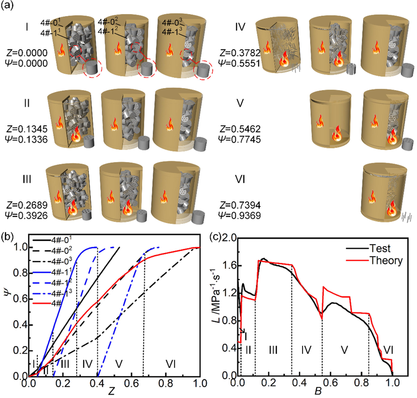
Closed vessel test and integrated numerical simulation results of shell-deterrent propellant mixed charges. (a) Burning surface regression simulation, (b) Integral and respective form functions, (c) Test and theory L-B curves.
The first stage was the combustion of shell propellants (4#-01, 4#-02, and 4#-03), which was similar to the first stage of SDP (3#).
In the second stage, the slivering behavior of the small-thickness shell propellant (4#-01) began, and its internal 7-perf propellants (4#-11) started to burn. The trend of Ψ increasing with Z was greater than that of the first stage. L-B curves went up sharply with the first rising step.
In the third stage, the slivering behavior of the shell propellant with medium thickness (4#-02) began, and its internal 7-perf propellants (4#-12) started to burn. The trend of Ψ increased further with Z. L-B curves rising dramatically again, and the second rising step appeared.
In the fourth stage, the slivering behavior of the first burning 7-perf propellants (4#-11) started until its burning ended. The trend of Ψ for 4#-11 decreased significantly with increasing Z, leading to the decrease in the trend of 4#, which was reflected in a significant fall in L-B curves.
Combined with Fig. 7b, the fifth stage can be divided into two segments. In the theoretical L-B curve, a rising step occurred in the front segment and a falling step in the back segment. In the former case, the slivering behavior of the shell propellant with a large thickness (4#-03) started and its internal 7-perf propellants (4#-13) started to burn. In the latter case, the second burning 7-perf propellants (4#-12) and the small-thickness shell propellant (4#-01) burned to the end. Similar to the analysis above, the gradual ignition process of 4#-12 and 4#-01 resulted in a gradual process at the end of the combustion. The test L-B curve exhibited a slow falling trend in advance, smoothed by the above two steps.
In the sixth stage, the slivering behavior of 4#-13 began, and the combustion of 4#-02, 4#-13, and 4#-03 ended successively. The tendency of Ψ decreased significantly with increasing Z. L-B curves dropped drastically to the end of the whole combustion process.
In summary, simulations and experiments of sequential superimposed combustion of several different customized zones for different charges open the door to customizing the combustion performance of mixed charges. Integrated simulation and MM-AM technology provide an efficient and common customization strategy to achieve the customization of mixed charges with more complex geometries and more material properties.
5 Conclusions
The customized strategy of mixed charges based on visual programming software Grasshopper and multi-material additive manufacturing was proposed for integrated simulation and experiment. The integrated simulation method of visual burning surface regression, form function calculation, and combustion performance prediction provided a convenient and effective guide for the design and optimization of complex structures (geometry and formulation) by comprehensively understanding the combustion process theoretically. A new generation of mixed charges in one propellant was presented and prepared, with complex geometries and multiple formulations co-constructed customized zones. Several different customized zones were superimposing combustion in the design sequence to achieve customized combustion performance. Whether burning surface or burning rate controlled mixed charges, the experimental phenomena of progressively random perforated combustion and variation of burning rate pressure exponent were well simulated. The experimental and simulated results of superimposed combustion of single and multiple charges with different customized zones were mirrored to each other according to the design sequence. As an advanced engineering strategy urgently needed in chemical engineering, this work not only fills the gap in mixed charges combustion performance simulation, but also serves as an efficient and common customization strategy from design to manufacture for mixed charges with more complex geometries and more material properties.
CRediT authorship contribution statement
Moru Wang: Data curation, Methodology, Software, Validation, Writing – original draft, Writing – review & editing. Guorui Jin: Investigation, Visualization, Writing – review & editing. You Fu: Data curation, Validation. Jinghao Liang: Data curation, Validation. Weidong He: Conceptualization, Project administration, Supervision, Writing – review & editing. Fengqiang Nan: Conceptualization, Supervision. Feiyun Chen: Validation, Supervision.
Acknowledgment
The authors would like to acknowledge the support of Key Laboratory of Special Energy Materials, Ministry of Education, Nanjing, 210094, China.
Declaration of Competing Interest
The authors declare that they have no known competing financial interests or personal relationships that could have appeared to influence the work reported in this paper.
References
- Additive manufacturing of multi-material structures. Mater. Sci. Eng. R: Reports. 2018;129:1-16.
- [CrossRef] [Google Scholar]
- Multi-objective optimization and rapid prototyping for jewelry industry: methodologies and case studies. Int. J. Adv. Manuf. Technol.. 2021;112(9–10):2943-2959.
- [CrossRef] [Google Scholar]
- Interior ballistics two-phase reactive flow model applied to small caliber projectile-gun system. Propellants Explos. Pyrotech.. 2015;40(5):720-728.
- [CrossRef] [Google Scholar]
- Estimation of the ballistic parameters of double base gun propellants. Propellants Explos. Pyrotech.. 2020;45(5):751-758.
- [CrossRef] [Google Scholar]
- Additive manufacturing of solid rocket propellant grains. J. Propul. Power. 2018;34(4):1090-1093.
- [CrossRef] [Google Scholar]
- Enhancement strategy of mechanical property by constructing of energetic RDX@CNFs composites in propellants, and investigation on its combustion and sensitivity behavior. Combust. Flame. 2022;244:112249
- [CrossRef] [Google Scholar]
- High energy propellants for advanced gun ammunition based on RDX, GAP and TAGN compositions. Propellants Explos. Pyrotech.. 2007;32(1):52-60.
- [CrossRef] [Google Scholar]
- Temperature sensitivity coefficients of RDX-based propellants and their mixed charges. Propellants Explos. Pyrotech.. 2021;46(10):1589-1597.
- [CrossRef] [Google Scholar]
- Structural design and calculation verification of special-shaped gun propellant. Chin. J. Explos. Propellants. 2021;44(05):698-704.
- [CrossRef] [Google Scholar]
- Material-structure-performance integrated laser-metal additive manufacturing. Science. 2021;372(6545)
- [CrossRef] [Google Scholar]
- Simple surface-tracking methods for grain burnback analysis. J. Propul. Power. 2015;31(5):1436-1444.
- [CrossRef] [Google Scholar]
- Combustion performance of single charge and mixed charge of 37-hole nitroguanidine propellant. Chin. J. Energ. Mater.. 2021;29(03):228-233.
- [CrossRef] [Google Scholar]
- 3D grain burnback analysis using the partial interface tracking method. Aerosp. Sci. Technol.. 2017;68:58-67.
- [CrossRef] [Google Scholar]
- Experimental study of possibilities for employment of linear form of burning rate law to characterise the burning process of fine-grained propellants. Cent. Eur. J. Energ. Mater.. 2008;5(1):45-61.
- [Google Scholar]
- On a certain method of determining the burning rate of gun propellant. Cent. Eur. J. Energ. Mater.. 2019;16(3):433-448.
- [CrossRef] [Google Scholar]
- Study of photocurable energetic resin based propellants fabricated by 3D printing. Mater. Des.. 2021;207:109891
- [CrossRef] [Google Scholar]
- Development and characterization of high performance solid propellants containing nano-sized energetic ingredients. Proc. Combust. Inst.. 2007;31(2):2089-2096.
- [CrossRef] [Google Scholar]
- Progress in additive manufacturing of energetic materials: creating the reactive microstructures with high potential of applications. Propellants Explos. Pyrotech.. 2019;44(8):941-969.
- [CrossRef] [Google Scholar]
- Influences of particle size and content of RDX on burning characteristics of RDX-based propellant. Aerosp. Sci. Technol.. 2014;32(1):26-34.
- [CrossRef] [Google Scholar]
- Development of a hybrid method in a 3-D numerical burn-back analysis for solid propellant grains. Aerosp. Sci. Technol.. 2020;106:106103
- [CrossRef] [Google Scholar]
- Burning behavior of nitramine gun propellants under the influence of pressure oscillations. Propellants Explos. Pyrotech.. 2010;35(3):284-291.
- [CrossRef] [Google Scholar]
- Parametric modeling program of single-layer spherical reticulated shell structure and prediction program of global stability ultimate bearing capacity. J. Phy. Conf. Ser.. 2021;1777(1):12034.
- [CrossRef] [Google Scholar]
- A new paradigm for star grain design and optimization. Aircr. Eng. Aerosp. Technol.. 2015;87(5):476-482.
- [CrossRef] [Google Scholar]
- Wall friction effects and viscosity reduction of gel propellants in conical extrusion. J. Non-Newton. Fluid Mech.. 2010;165(13–14):782-792.
- [CrossRef] [Google Scholar]
- Solid rocket motor propellant grain burnback simulation based on fast minimum distance function calculation and improved marching tetrahedron method. Chin. J. Aeronaut.. 2021;34(4):208-224.
- [CrossRef] [Google Scholar]
- HMX based enhanced energy lova gun propellant. J. Hazard. Mater.. 2007;143(1–2):532-534.
- [CrossRef] [Google Scholar]
- Development of propellant compositions for vat photopolymerization additive manufacturing. Propellants Explos. Pyrotech.. 2019;45(1):36-52.
- [CrossRef] [Google Scholar]
- Closed vessel burning behavior and ballistic properties of artificially-degraded spherical double-base propellants stabilized with diphenylamine. Thermochim. Acta. 2019;680:178347
- [CrossRef] [Google Scholar]
- Optimization of building form to minimize energy consumption through parametric modelling. Procedia Environ. Sci.. 2017;38:509-514.
- [CrossRef] [Google Scholar]
- Voxelprint: a grasshopper plug-in for voxel-based numerical simulation of concrete printing. Autom. Constr.. 2021;122:103469
- [CrossRef] [Google Scholar]
- Analysis the burning area of complicated grain based on UG. J. Projectiles, Rockets, Missiles Guidance. 2004;S8:319-321.
- [CrossRef] [Google Scholar]
- Extrusion 3D printing technology of double base gun propellants. Chin. J. Energ. Mater.. 2022;30(9):897-902.
- [CrossRef] [Google Scholar]
- 3D printing of gun propellants based on laminated object manufacturing. Mater. Manuf. Process.. 2022;37(11):1246-1256.
- [CrossRef] [Google Scholar]
- Integration of complex geometry gun propellant form function calculation and geometry optimization. Propellants Explos. Pyrotech.. 2022;47(9)
- [CrossRef] [Google Scholar]
- Combined acceleration methods for solid rocket motor grain burnback simulation based on the level set method. Int. J. Aerosp. Eng.. 2018;2018:1-12.
- [CrossRef] [Google Scholar]
- Modeling, simulation and characterization of complex shaped solid propellant combustion. Propellants Explos. Pyrotech.. 2017;42(7):736-748.
- [CrossRef] [Google Scholar]
- Deconsolidation and combustion performance of thermally consolidated propellants deterred by multi-layers coating. Def. Technol.. 2014;10(2):101-105.
- [CrossRef] [Google Scholar]
- Emulation and calculation of the burning surface of 3D grains of partially cut multi-perforated stick propellant using the level set method. Propellants Explos. Pyrotech.. 2016;41(1):148-153.
- [CrossRef] [Google Scholar]
- Application of Solid Works API of grain burning surface calculation. J. Aerosp. Power.. 2008;08:1536-1540.
- [CrossRef] [Google Scholar]
- Constant-volume combustion performance of mixed charge of slotted stick propellants and coated granular propellants. Chin. J. Energ. Mater.. 2017;25(01):39-43.
- [CrossRef] [Google Scholar]
- Fabrication and investigation of 3D-printed gun propellants. Mater. Des.. 2020;192:108761
- [CrossRef] [Google Scholar]
- Constant-volume combustion performance of mixed charge of foamed propellant with nitramine propellant. Journal of physics. J. Phys. Conf. Ser.. 2020;1507(2):22002.
- [CrossRef] [Google Scholar]
- Calculated combustion behavior of multi-perf disk (MPD) gun propellant in closed bomb. Chin. J. Explos. Propellants. 2021;44(04):538-542.
- [CrossRef] [Google Scholar]
- Numerical calculation of combustion performance of layered variable burning rate gun propellant. Chin. J. Explos. Propellants. 2021;44(02):252-257.
- [CrossRef] [Google Scholar]
- 3D printing of multi-material composites with tunable shape memory behavior. Mater. Des.. 2020;193:108785
- [CrossRef] [Google Scholar]
- Calculation and experimental study on combustion performance of variable-burning rate propellant. J. Solid Rocket Technol.. 2019;42(02):205-209.
- [CrossRef] [Google Scholar]
- Three-dimensional printing of energetic materials: a review. Energ. Mater. Front.. 2022;3(2):97-108.
- [CrossRef] [Google Scholar]


