

Translate this page into:
A review on the development of a porous carbon-based as modeling materials for electric double layer capacitors
-
Received: ,
Accepted: ,
This article was originally published by Elsevier and was migrated to Scientific Scholar after the change of Publisher.
Peer review under responsibility of King Saud University.
Abstract
Carbon electrodes are a key factor for electric double layer capacitors (EDLCs). Carbon gels have high porosity with a controllable pore structure by changing synthesis conditions and modifying preparation processing to improve the electrochemical performance of EDLCs. This review summarizes the preparation of carbon gels and their derivatives, the criteria to synthesize high surface area in each process, the development by some carbon forms, and EDLC applications. Porous carbons are also prepared as model materials by concentrating on how pore structure increases electrochemical capacitance, such as electronic and ion resistance, the tortuosity of pore channel, suitable micropore and mesopore sizes, and mesopore size distribution. This review emphasizes the significance of pore structures as the key factor to allow for the design of suitable pore structures that are suitable as the carbon electrode for EDLCs.
Keywords
Carbon gels
Carbon/carbon composites
Electric double layer capacitors
Ion transfer
Model materials

- ACF
-
Activated carbon fiber
- BET
-
Brunauer, Emmett and Teller
- C/C
-
Carbon/carbon
- C
-
Catalyst
- CF
-
Cotton fiber
- EDLC
-
Electric double layer capacitor
- F
-
Formaldehyde
- R
-
Resorcinol
- R/C
-
Resorcinol and catalyst ratio
- RF
-
Resorcinol and formaldehyde
- RFu
-
Resorcinol and furfuraldehyde
- R/W
-
Resorcinol and water ratio
- TBA
-
Tertiary butanol
- TCX
-
Templated carbon xerogel
- YS-CS
-
York-shell carbon sphere
Abbreviations
1 Introduction
Porous carbon materials are prepared by various methods and have various names which are related to their preparation methods or their forms such as activated carbons, carbon gels, carbon foams, activated carbon fibers, carbon filaments, template carbons, carbon/carbon (C/C) composite gels, carbon nanotubes, multi-wall nanotubes, carbon microspheres, graphene, graphite, carbon beads, cellulose-based materials (Dutta et al., 2017), metal–organic-framework derived materials (Konnerth et al., 2020), Carbon nanosheets (Wang et al., 2018) and biomass-derived materials (Matsagar et al., 2021). The porous carbons can be applied in the various purposes in the science and the engineering such as adsorption, catalysis, water purification, waste treatment, and energy storage devices.
Activated carbons are widely known as a porous carbon material used in academic research and by various industries due to its high specific surface area (Yahya et al., 2015), but they have a small mesopore volume. Most of the porous structure of an activated carbon has micropores principally. Their starting materials were obtained from low-cost carbon sources such as agricultural waste (Yahya et al., 2015), municipal waste (Nagano et al., 2000), and plastic waste (Kadirova et al., 2006). Therefore, activated carbon is very cheap to produce. Activated carbons can be prepared from the carbonization of carbon sources followed by physical activation or chemical activation. Occasionally, activated carbons can also be synthesized by the carbonization and the activation simultaneously (Yahya et al., 2015; Inagaki, 2009). CO2 and steam have been generally used for the physical activation. Some chemicals such as ZnCl2, NaOH, H3PO4, and KOH are used to increase the porous properties by chemical activation. The surface area of activated carbon by KOH activation could obtain up to 3,350 m2 g−1 (Linares-Solano et al., 2007). Yet extremely high porous activated carbon results in weak mechanical strength. Activation can be enabled to create mesopores by CO2 or steam, but the pore sizes of such activated carbon are usually less than 3 nm (Yahya et al., 2015). The pore sizes of activated carbons cannot be controlled because the primary structure of a starting material specifies the pore size of an activated carbon. However, carbon gels can have highly porous properties and the pore structure can be controlled, meaning that the carbon can be used as the carbon electrode for electric double layer capacitors (EDLCs).
2 Carbon gel
Carbon gel is a class of mesoporous carbon materials prepared by sol–gel polycondensation. The carbon gel is typically named by drying method: carbon aerogel dried by supercritical drying, carbon cryogel dried by freeze drying and carbon xerogel dried by subcritical drying. Besides the drying method, the progress in the carbon gel is also further applied by the templating technique as porous carbon in various names. In this review, carbon gel is categorized in carbon aerogel, carbon cryogel, carbon xerogel, and porous carbon.
2.1 Carbon aerogel dried by supercritical drying
Carbon aerogels were initially obtained by sol–gel polymerization with catalyst (C) solution. Resorcinol (R) was popular as starting materials reacting with aldehyde. Formaldehyde (F) and furfuraldehyde were selected as aldehyde. Furthermore, wattle tannin as a bioresource could react with formaldehyde or furfural, forming tannin gels by sol–gel method. They were dried by supercritical method and carbonized becoming the carbon aerogels. Their porous structures can vary based on the number of reactants, catalysts, and the amount of distilled water (Al-Muhtaseb and Ritter, 2003; Tamon et al., 1998).
Pekala prepared the typical carbon aerogel from resorcinol and formaldehyde (RF) in 1989. Using resorcinol as the phenol derivatives reacted quicker than phenol because of the high electron density at the 2,4,6 benzene-ring positions (Pekala, 1989). The high electron densities at the 2,4,6 benzene-ring positions induced formaldehyde forming hydroxymethyl derivatives of resorcinol. The hydroxymethyl groups on resorcinol reacted together using the condensation reaction allowing the methylene bridge (-CH2-) and the methylene-ether bridge (-CH2-O-CH2-). The chains grew slowly to polymerize the RF resin as shown in the schematic diagram in Fig. 1(a). The methylene-ether bridges were unstable because of the disproportionation transforming the methylene bridges and releasing formaldehyde. When the hydroxymethyl derivatives of resorcinol were formed and dispersed in the RF solution, they polymerized turning into the small RF clusters about 7–10 nm. The RF clusters connected and became the RF wet gel (Pekala, 1989). These phenomena can occur at both ambient and higher temperatures. The higher temperature accelerated the gelation time. Curing was also required to increase the stiffness of RF wet gel. The typical curing temperature and duration was approximately 85–95 °C for 3–7 days (Pekala, 1989; Pekala et al., 1992; Pekala and Schaefer, 1993; Tamon et al., 1997; Tamon and Ishizaka, 1998). Dilute acid pretreatment can be applied to maximize the methylene bridge (Pekala and Schaefer, 1993; Pekala, 1989; Pekala et al., 1992) in Fig. 1(b).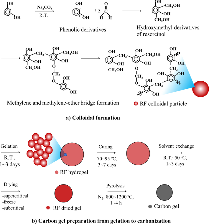
Schematic diagram of sol–gel polycondesation of resorcinol and formaldehyde to carbon gel: a) colloidal formation and b) carbon gel preparation from gelation to carbonization.
The RF gel had a micropore structure inside the RF clusters and the mesopore structure formed by the voids among the RF clusters. The gel structure could be ruined by the capillary force from the gas–liquid interface during the drying process. Supercritical drying by CO2 operated above its critical point (Pc = 7.4 MPa and Tc = 31 °C) was applied by drying to avoid a gas–liquid interface (Pekala, 1989; Pekala et al., 1992; Pekala and Alviso, 1992; Pekala and Schaefer, 1993; Tamon et al., 1997; Tamon and Ishizaka, 1998). Liquid CO2 is immiscible with water, so solvent exchange was required by replacing water inside the RF wet gel with another organic solvent such as acetone (Pekala et al., 1992; Pekala and Schaefer, 1993; Tamon and Ishizaka, 1998). The RF gel exchanged by acetone was placed in a pressure vessel or an autoclave. Liquid CO2 was pumped into the autoclave replacing acetone with CO2 in the RF gel. Subsequently, the autoclave was operated above the critical point such as Pc = 11 MPa and Tc = 45 °C (Al-Muhtaseb and Ritter, 2003). The dried RF aerogel was further carbonized at high temperatures above 800 °C in an inert atmosphere to receive the carbon aerogel.
Carbon aerogels generally result in high porosity with a high surface area up to 1,920 m2 g−1 (Tamon et al., 1997), and the large mesopore volume up to 2.81 cm3 g−1 (Tamon et al., 1998). Although the mesopores could shrink by 1–4 nm during carbonization (Tamon et al., 1998), the micropores could develop regularly (Tamon et al., 1997). The mesopore volume of carbon aerogels can be increased by pyrolysis when the RF aerogel had a dispersed mesopore structure (Tamon et al., 1997). In contrast, the mesopore volume of the RF aerogel with a monodisperse structure was decreased by pyrolysis (Tamon et al., 1997). Yet the shape of the mesopore size distribution of carbon aerogels was maintained as that of RF aerogel by pyrolysis (Tamon et al., 1998). Their mesopore structure could be controlled by the synthesis condition varying the resorcinol and catalyst ratio (R/C) and the resorcinol and water ratio (R/W) in the range of 2.5–9.2 nm as shown in Fig. 2 (Tamon et al., 1998; Yamamoto et al., 2001). The carbon aerogels could be used as column packing materials for high-performance liquid chromatography, adsorbents, catalyst supports, and carbon electrodes. However, supercritical drying requires complicated operations at a high pressure using an expensive high-pressure vessel.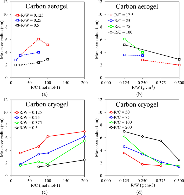
Mesopore radius control of carbon aerogels and carbon cryogels by R/C and R/W ratios. Plotted from the data set of carbon aerogels (Tamon et al., 1998) and carbon cryogels (Yamamoto et al., 2001).
2.2 Carbon cryogel dried by freeze drying
Freeze drying is an easier and cheaper drying method than supercritical drying and was applied for the preparation of mesoporous carbon. The RF gels dried by freeze drying were named RF cryogels. The freeze-dried RF gels without the solvent exchange were prepared (Mathieu et al., 1997; Kocklenberg et al., 1998) and water filled in the RF gels was solidified by freezing. The R/C ratio played an important role to prevent pore collapse due to ice growth during the freezing process, thereby allowing an almost constant surface area up to 464 m2 g−1 (Mathieu et al., 1997). But ice growth which contributed to volume expansion could occur during the drying stage (Kocklenberg et al., 1998). To prevent ice growth, water inside a gel structure should be exchanged by an organic solvent with a low volume expansion. Tamon et al. successfully prepared RF cryogels and carbon cryogels with a wide range of synthesis conditions by suppressing pore collapse through the solvent exchange with tertiary butanol (TBA) before freeze drying and pyrolysis in an inert atmosphere (Tamon et al., 1999; Tamon et al., 2000; Tamon et al., 2001; Yamamoto et al., 2001; Yamamoto et al., 2001). The RF gel filled by TBA was frozen below the freezing point (25–25.5 °C). The typical pre-freezing temperature could be operated at −30 °C for approximately 6 h and then dried at −10 °C (Tamon et al., 1999; Tamon et al., 2000; Tamon et al., 2001; Yamamoto et al., 2001; Yamamoto et al., 2001). Carbon cryogel also presented a high surface area up to 1,203 m2 g−1 and a large mesopore volume up to 1.54 cm3 g−1 (Tamon et al., 1999; Tamon et al., 2001). Although the pyrolysis of RF cryogels could develop microporosity like the RF aerogels, the pore collapse in the carbon cryogels was found by carbonizing the RF cryogels (Yamamoto et al., 2001).
2.3 Carbon xerogel dried by subcritical drying
Some carbon xerogels were dried by subcritical drying (Mayer et al., 1995; Wiener et al., 2004). Unlike the supercritical drying and the freeze drying avoiding the capillary force by own drying technique, the subcritical drying requires the solvent exchange significantly decreasing the capillary force. Double solvent exchange was used by acetone followed by cyclohexane (Mayer et al., 1995). Without the solvent exchange, the initial pH in the carbon xerogel preparation was needed to control the porosity. The initial pH over 6.25 contributed to non-porous carbon xerogels. The initial pH ≤ 6.25 gave a surface area in the range of 550–650 m2 g−1 with the total void volume between 0.4 and 1.4 cm3 g−1. Yet such carbon xerogels have high mesopore volume with a very large mesopore diameter. The shrinkage, cracking, and textural properties of RF xerogels are dependent on the recipe rather than the drying operation (Job et al., 2006). A high R/C ratio at 1,000 mol mol−1 can suppress shrinkage. The lower R/C ratio influenced greater shrinkage (Job et al., 2006). The surface area of dried gel was small with many macropores. Nonetheless, the drying methods to synthesize carbon xerogels were also observed such as evaporation drying (Matos et al., 2006; Yamamoto et al., 2001; Mayer et al., 1995; Wu et al., 2004; Wiener et al., 2004; Zubizarreta et al., 2008; Czakkel et al., 2005; Kraiwattanawong et al., 2011), convective hot gas drying (Tamon et al., 1999; Hebalkar et al., 2005; Job et al., 2006; Zubizarreta et al., 2008), microwave drying (Yamamoto et al., 2001; Zubizarreta et al., 2008), and vacuum drying (Tamon et al., 1999; Job et al., 2005; Zubizarreta et al., 2008; Kraiwattanawong et al., 2011). These forms of subcritical drying resulted in lower porous properties compared with freeze drying, both with and without solvent exchange (Job et al., 2005; Kraiwattanawong et al., 2011). Nevertheless, subcritical drying with the exchanged organic solvent provides advantages by requiring low cost drying equipment and easy operations.
Various organic solvents in the solvent exchange have been including water (Job et al., 2004; Wiener et al., 2004; Kraiwattanawong et al., 2011; Job et al., 2006; Job et al., 2005), methanol (Zubizarreta et al., 2008), ethanol (Hebalkar et al., 2005; Kraiwattanawong et al., 2011), acetone (Mayer et al., 1995; Lin and Ritter, 1997; Matos et al., 2006; Wiener et al., 2004; Czakkel et al., 2005; Kraiwattanawong et al., 2011), isopropanol (Wu et al., 2004), TBA (Yamamoto et al., 2001; Kraiwattanawong et al., 2011), and toluene (Kraiwattanawong et al., 2011). Compared to water, organic solvent can better decrease the capillary force thereby alleviating the mesoporous collapse of carbon xerogels. Acetone (Lin and Ritter, 1997; Matos et al., 2006) and ethanol (Hebalkar et al., 2005), initially used as the solvent filled in the RF gels dried by a subcritical drying, contributed surface areas up to 700 and 500 m2 g−1, respectively. By using subcritical drying and ethanol as the solvent, the pore structure of carbon aerogel (named by the authors) shrank during carbonization as the SEM images in ref. (Hebalkar et al., 2005). The organic solvent could partially protect pore shrinkage due to the gas–liquid interface (Mayer et al., 1995; Lin and Ritter, 1997; Hebalkar et al., 2005; Matos et al., 2006; Wu et al., 2004; Wiener et al., 2004; Zubizarreta et al., 2008; Czakkel et al., 2005; Kraiwattanawong et al., 2011).
Preparation time can be reduced by preparing carbon aerogels (subcritical conditions) under a high R/C ratio in the range of 1,000–3,000 mol mol−1 with acetone as solvent heated to 90 °C (Wiener et al., 2004). This method decreased particle size and pore size slightly, but they could compensate with the R/C increase. Therefore, the high R/C ratio resulted in low shrinkage similar to the previous work (Job et al., 2004). Yet the pore sizes of carbon aerogels collapsed when water acted as the solvent to produce a high capillary force exerted on the tiny pore. Various drying methods (conventional oven, convective drying, microwave, vacuum drying) were applied for the carbon xerogels using methanol as the solvent leading to the microporous carbon xerogels (Zubizarreta et al., 2008). The carbon xerogel activated was prepared at the R/C ratio of 1,000 mol mol−1 with 40% of burn-off occupying the surface area about 1,340 m2 g−1 with the type I of isotherm by IUPAC.
Czakkel et al. investigated the effect of drying method on the morphology of dried gels and carbon gels (Czakkel et al., 2005). SEM images of RF gels dried by supercritical drying, freeze drying, and hot air convective drying. The pore structure of a cryogel (TBA as solvent) was loose, whereas the others (acetone as solvent) were packed. In this work, the carbon cryogels possessed a surface area of about 2,650 m2 g−1, whereas the carbon aerogel and the carbon xerogel occupied a surface area of about 1,010 and 891 m2 g−1, respectively. Although supercritical drying is highly efficient to prepare porous carbon aerogels, the solvent can play a crucial role in producing highly porous carbon gels.
The high R/C ratio (1,000–3,000 mol mol−1) contributed the large nanoparticles protecting the pore shrinkage (Job et al., 2006; Wiener et al., 2004), whereas the low R/C ratio could not endure the pore collapse well (Job et al., 2006). The solvent species (water, methanol, ethanol, TBA, toluene) cooperated by evaporation drying and vacuum drying were observed by the preparation of mesoporous carbon xerogels with the R/C ratio in the range of 200–500 mol mol−1 (Kraiwattanawong et al., 2011). The high R/C ratio at 500 mol mol−1 resisted the capillary force exerted on the mesopore structure, thereby allowing porous carbon xerogels by evaporation drying and vacuum drying. However, the low R/C ratio at 200 mol mol−1 could not withstand the mesopore shrinkage. The gas–liquid interface played an important role in determining the porosity of carbon xerogels, but vacuum drying can alleviate the capillary force. The solvent species relieved the effect of the capillary force to a great extent. The toluene-used carbon xerogel could result in a surface area up to 1,040 m2 g−1, but the mesopore radius implies that the mesopore shrinkage was greater than the TBA-used carbon xerogel. Therefore, the preparation of mesoporous carbon xerogels (aerogels) dried by subcritical drying needed (i) a suitable drying method, (ii) solvent exchange must occupy a low surface tension, low- or non-polarity, and the low vapor pressure, and (iii) the synthesis condition (Kraiwattanawong et al., 2011). Among the studied solvents, TBA was suggested in the solvent exchange for the preparation of mesoporous carbon xerogels.
Many variables influenced the porous properties of the carbon gels such as the synthesis condition, the synthesis technique, the solvent used during preparation and solvent exchange, and the drying control. The influence of drying method is dependent on the existence of gas–liquid interface. In conclusion, the avoidance of gas–liquid interface is a key factor to efficiently dry the porous carbon gels with supercritical drying or freeze drying. When the gas–liquid interface appears, the range of initial recipes will be limited by capillary force in the tiny pores. The high R/C ratio is required. The solvent exchange is therefore the significant role decreasing such capillary force effectively and allowing the wide range of initial chemical ratios.
2.4 Porous carbons using the templating technique
Templating techniques can be applied for the preparation of the porous carbon materials with the hard or soft template in uniform shape like nanoporous carbon spheres. The C/C composite gels and templated carbon gels are further progressed in the non-uniform porous carbon. Since the variety of templated carbons is different from the carbon gel, this review will classify the porous carbon as followings: nanoporous carbon spheres, C/C composite gels, and templated composite gels.
2.4.1 Nanoporous carbon spheres
Nanoporous carbon spheres can be prepared by the template technique, starting from organic-inorganic composites or surfactants-assisted. Nanoporous carbon spheres could use the porous inorganic material such as silica as the template. Then, the inorganic materials are removed by chemicals such as hydrofluoric acid (Nakamura et al., 2009; Hu et al., 2008; Valle-Vigon et al., 2010) and sodium hydroxide (Hu et al., 2008). Nakamura et al. found that monodisperse carbon spheres with a high surface area and large pore volume could suppress pore collapse (Nakamura et al., 2009). The nanoporous carbon spheres occupied the surface area and the pore volume up to 1,780 m2 g−1 and 0.89 cm3 g−1, respectively. Hu et al. synthesized nanoporous carbon spheres enhancing the reversible and fast sorption for hydrogen storage (Hu et al., 2008). The silica template precursors and its type could control the pore size and the porous properties with a narrow pore size distribution. Their surface area and pore volume could contribute up to 2,000 m2 g−1 and 4.0 cm3 g−1. Using the core–shell structure could provide the mesoporous carbon capsules with a surface area and total pore volume up to 1,620 m2 g−1 and 2.3 cm3 g−1. However, the preparation of nanoporous carbon spheres spends long periods to synthesize the mesoporous silica and the silica etching. Spherical carbon gels could be prepared by using SPAN80, a surfactant, under inverse emulsion polymerization with the surface area about 750 m2 g−1 applied as a packing material for high-performance liquid chromatography (Yamamoto et al., 2002). Horikawa et al. utilized a surfactant-active reagent possessing the low hydrophile–lipophile balance value which produced a spherical carbon aerogel with a surface area of about 800 m2 g−1 and the mesopore volume was up to 0.6 cm3 g−1 (Horikawa et al., 2004).
2.4.2 Carbon/carbon composite gels
C/C composite gels enable preparation by mixing the disperse phase and the matrix derived from the carbon-source substances. The disperse phase in a C/C composite could be used from the various materials such as cellulose (Wang et al., 2001), carbon cloth (Wang et al., 2001; Schmitt et al., 2001), activated carbon fibers (ACF) (Fu et al., 2003), and polymeric fibers (Petricevic et al., 2001). The matrix can be synthesized from polymeric substance such as RF resin and RFu (furfuraldehyde) resin. Fu et al. prepared the ACF/carbon aerogels from resorcinol and furfural (Fu et al., 2003). If RFu gels are prepared with a low mass density, the ACF addition to the RFu gel somewhat reinforces the mechanical properties. The porosity of C/C composites also depended on the ACF quantity. Therefore, the C/C composite gels allows preparation of a pore structure which serves both scientific and engineering purposes.
The C/C composite cryogels were designed using the sol–gel polycondensation mixed with cotton fibers (CFs) (Kraiwattanawong et al., 2011; Kraiwattanawong et al., 2012; Kraiwattanawong et al., 2013). Here CFs, a cheap and naturally renewable substance, could be represented as the dispersed phase in the RF gel matrix forming a CF/RF composite cryogel dried by the freeze-drying method. The addition of CF increases the mesopores with an unimportant change of mesopore size compared with ordinary carbon cryogel under the same RF recipe (Kraiwattanawong et al., 2011). The structure of C/C composites was heterogeneous and is comprised of a mesoporous carbon matrix and carbon tunnels as shown in Fig. 3 (Kraiwattanawong et al., 2012). Here, the carbon tunnels contained (i) carbon fibers, (ii) spaces between carbon fibers and nanoporous carbon spheres, (iii) nanoporous carbon spheres with surrounding nanocages, and (iv) dense ring structures. It is believed that carbon tunnels as the macropores could enhance the mass transfer inside the C/C composite materials. The C/C composite cryogels occupied the surface area and mesopore volume up to 990 m2 g−1 and 1.71 cm3 g−1 (Kraiwattanawong et al., 2013).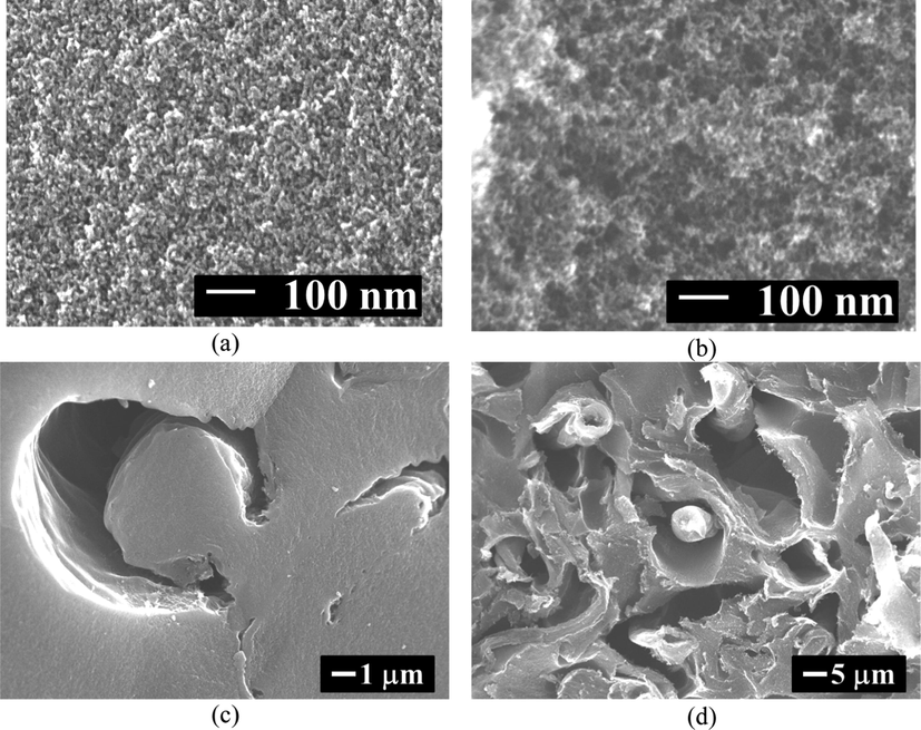
Carbon structure of C/C composites: (a) matrix of A0, (b) matrix of C0, (c) C/C structure of A1 and (d) C/C structure of C1. Reproduced and edited from SEM images with permission Elsevier (Kraiwattanawong et al., 2012).
2.4.3 Templated carbon gels
Templated carbon gels could be synthesized by CF elimination from the CF/RF composite hydrogels with sulfuric-acid dehydration. CF is a cellulose possessing the linear polymer consisting of many glucose units by structure by β-1,4-glucosidic linkages (Klemm et al., 2005). CFs contain a large quantity of hydroxyl groups forming the hydrogen bond between the molecular chains. Although CFs have hydroxyl groups, the high molecule weight results in being insoluble in water. These linkages could be broken using dilute acid, concentrated acid, or enzymes to receive monosaccharide (Balat et al., 2008). Dilute sulfuric acid, a popular chemical for acid hydrolysis, was blended with biomass before hydrolyzing the cellulose to pentoses and hexoses (Chen et al., 2007). Since 5-carbon sugars degraded more rapidly than 6-carbon sugars, the dilute acid hydrolysis was divided to two stages; a mild temperature to recover pentoses and a high temperature to recovery hexoses (Demirbas, 2007). Concentrated sulfuric or hydrochloric acid was used to hydrolyze lignocellulosic materials to 5-carbon sugars only at the mild temperature. The reaction time for concentrated acid was shorter than for the dilute acid. The concentrated sulfuric acid performed about 70% at 313–323 K for 2–4 h in a reactor (Balat et al., 2008).
Templated carbon xerogels (TCXs) formed straight holes as the macroporous structure by CF removal from the CF/RF composite hydrogel (Kraiwattanawong, 2019; Kraiwattanawong, 2020) in Fig. 4. The remained-RF matrix contributed to the microporous and mesoporous structure. Thereby, TCXs comprised the trimodal structure of micropores, mesopores, and macropores. The number of macropores could be controlled by the size and the quantity of CFs, while the micropores and the mesopores could be controlled by the RF recipe. Evaporation allowed the scaffold carbon xerogels as the macropore wall, whereas vacuum drying contributed to sponge-like carbon xerogels as the macropore wall, as presented in Fig. 5 (Kraiwattanawong, 2020). Under the synthesis condition, the evaporation provided the surface area and mesopore volume up to 608 m2 g−1 and 0.80 cm3 g−1, whereas vacuum drying permitted the surface area and mesopore volume up to 666 m2 g−1 and 1.40 cm3 g−1. Vacuum drying more efficiently developed the mesopore structure of TCXs than evaporation drying. Although the two drying methods gave nearly the same surface area, the existence of sponge-like carbon xerogels dried by vacuum drying resulted in improved electrochemical behavior (Kraiwattanawong, 2020). Therefore, the sponge-like carbon xerogels promoted the mass transfer from the bulk solution into the microporous surface. The scaffold carbon xerogels appeared as a dense wall which obstructed the mass transfer. Therefore, vacuum drying was advantageous for TCX synthesis.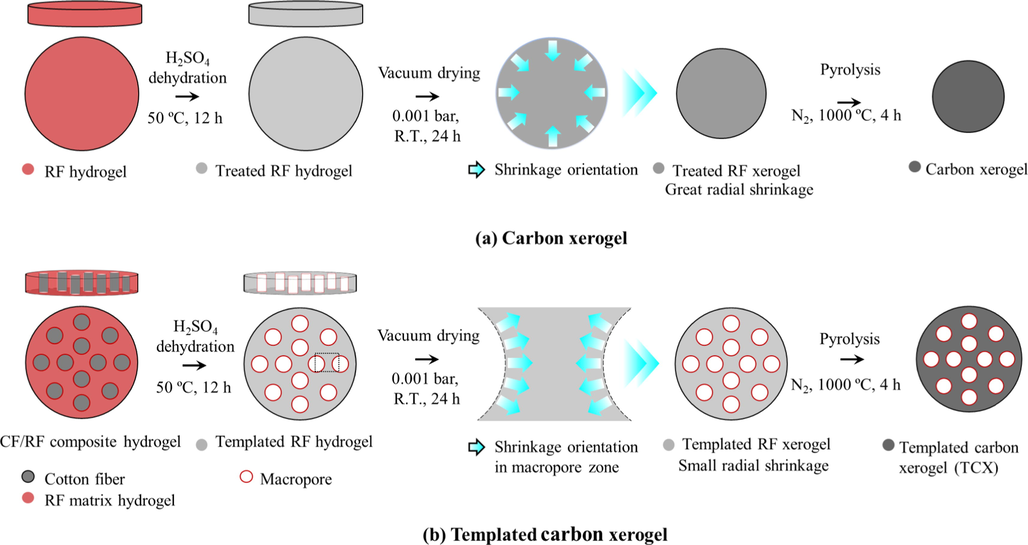
Schematic diagram of TCX preparation: (a) carbon xerogel without CF utilization and (b) templated carbon xerogel with CF utilization. Reproduced and edited with permission Elsevier (Kraiwattanawong, 2020).
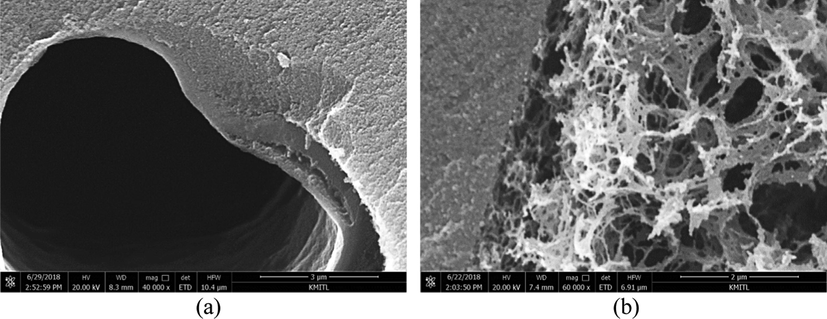
Structure of a macropore wall of TCXs: (a) packed wall by evaporation, and (b) porous wall by vacuum drying. Reproduced and edited from SEM images with permission Elsevier (Kraiwattanawong, 2020).
3 Electric double layer capacitors
Porous carbon materials could be applied for energy storage devices because of their accessibility, easy processability, and relatively low cost. There have therefore been many studies into porous carbon materials. The key factors for the carbon electrode include surface area, pore geometry, pore size distribution and size, conductivity and resistivity, wettability, accessibility, and electroactive species (Frackowiak and Beguin, 2001). Capacitors can generally be categorized into two types, either electric double layer capacitors (EDLCs) based on the electrostatic phenomena or pseudo-capacitors which rely on the redox reaction (Frackowiak and Beguin, 2001; Inagaki et al., 2010; Frackowiak, 2007; Simon and Gogotsi, 2008; Zhang and Zhao, 2009).
Microporous carbon materials are incapable of promoting the electric double layer due to ion inaccessibility in pores (Frackowiak and Beguin, 2001; Inagaki et al., 2010). The mesopores were also needed by playing the role of fast ion migration and delivering high energy at a high rate (Frackowiak and Beguin, 2001). Babic et al. proposed that the total specific capacitance should be considered by the capacitance from micropore areas and the capacitance from mesopore areas (Babic et al., 2004). The specific capacitance was linearly dependent on the reciprocal of the square root of the potential scan rate. Nevertheless, the principal EDLC performance is more dependent on the microporous specific capacitance than the mesoporous specific capacitance. Some porous carbons for the EDLC electrodes prepared by the carbonization and the activation are summarized in Tables 1 and 2. NR = Not reported; NC = Not calculated since insufficient data. NR = Not reported; NC = Not calculated since insufficient data. a Calculated from the apparent density or the given electrode dimension reported in the article.
Material
Solvent exchange
Drying method
Pyrolysis (°C) (time)
Surface area (m2 g−1)
Electrolyte
Cell electrode system
Specific capacitance (F g−1)
Volumetric capacitance (F cm−3)
Areal capacitance (µF cm−2)
Discharge time (s)
Ref.
Carbon aerogel
ethanol
subcritical
1,050 (24 h)
500
1 M H2SO4
3
114
44 ± 2
NC
NC
(Hebalkar et al., 2005)
C/C composite cryogel
tert-butanol
freeze
1,000 (4 h)
990
4 M KOH
3
197
32.0
19.9
c1,974
(Kraiwattanawong et al., 2013)
Templated carbon xerogel
tert-butanol
vacuum
1,000 (4 h)
666
4 M KOH
3
317
a164.8
b47.6
c1,518
(Kraiwattanawong, 2020)
Carbon cryogel
tert-butanol
freeze
800
739
0.5 M HClO4
2
156
NC
b20.0
NC
(Babic et al., 2004)
Porous carbon
NR
NR
1,000 (4 h)
1,217
2 M H2SO4
3
127
NC
11.2
NC
(Moriguchi et al., 2004)
York shell carbon sphere
NR
evaporation
700 (3 h)
1,046
6 M KOH
3
2120
NC
b11.5
d ∼ 185
(Wang et al., 2015)
1 M (C2H5)4NBF4(TEABF4)
75
NC
b7.2
NC
Carbon aerogel
acetone
subcritical
800 (2 h)
847
1 M TEABF4-ACN
2
20
a25.0
b2.4
d ∼ 450
(Yang et al., 2017)
Ordered mesoporous carbon
NR
NR
800 (3 h)
590
1 M H2SO4
2
196
NC
33.0
NC
(Matsui et al., 2013)
Carbon sphere
NR
subcritical
800 (1 h)
800
1 M H2SO4
3
196
NC
24.5
NC
(Tanaka et al., 2012)
Powdery carbon aerogel
NR
NR
900 (10 h)
2,052
6 M KOH
2
384
NC
b18.7
d ∼ 450
(Xu et al., 2017)
Carbon cryogel
tert-butanol
freeze
900 (2 h)
1,228
4 M H2SO4
3
109
a11.3
b8.9
NC
(Amaral-Labat et al., 2012)
Carbon xerogel
acetone
evaporation
850 (1 h)
776
751
7511 M H2SO4
3
132
a52.8
b17.0
NC
(Zeller et al., 2012)
1 M TEABF4-AN
3
52
a34.8
b6.9
NC
1 M TEABF4-GBL
3
46
a30.8
b6.1
NC
Material
Solvent exchange
Drying method
Pyrolysis (°C) (time)
Activated agent
Activation condition(°C) (time)
Surface area(m2 g−1)
Electrolyte
Cell electrode system
Specific capacitance (F g−1)
Volumetric capacitance (F cm−3)
Areal capacitance (µF cm−2)
Discharge time (s)
Ref.
Activated carbon xerogel
acetone
convective
1,050 (3 h)
CO2
1,050 (3 h)
1,629
30 wt% H2SO4
3
175
NC
b10.7
NC
(Lin et al., 1999)
Activated carbon
NR
NR
NR
NR
NR
2,130
30 wt% KOH
2
100
NC
b4.7
NC
(Qu and Shi, 1998)
Activated carbon
NR
NR
NR
NR
NR
1,890
1.7 M TEAMS in AN
2
125
NC
b6.6
d ∼ 150
(Gamby et al., 2001)
Activated
NR
NR
520 (2 h)
KOH
700 (1 h)
2,740
6 M KOH
2
286
c460
10.4
NC
(Raymundo-Pinero et al., 2006)
carbon
1 M H2SO4
2
NC
NC
NC
NC
1 M TEABF4-AN
2
NC
NC
NC
NC
Activated carbon nanofibers
NR
NR
NR
CO2
900 (1 h)
1,005
6 M KOH
3
193
NC
b19.2
d ∼ 175
(Qian et al., 2020)
Activated carbon
NR
NR
450 (0.5 h)
CO2
800 (1 h)
751
6 M KOH
2
92.7
NC
b12.3
d ∼ 350
(Jiang et al., 2020)
N-doping carbon sphere
NR
NR
800 (3 h)
CO2
900 (6.5 h)
3,981
6 M KOH
2
360
NC
b9.0
d ∼ 575
(Kim et al., 2019)
Activated carbon xerogel
tert-butanol
evaporation
1,000 (4 h)
CO2
1,000 (2 h)
2,965
30 wt% H2SO4
2
251
25.6
b8.5
d ∼ 500
(Tsuchiya et al., 2014)
Activated hydrochar
NR
NC
250 (2 h)
KOH
800 (1 h)
3,280
EMImTFSI/AN
2
170
NC
b5.2
d ∼ 5
(Fuertes and Sevilla, 2015)
Ordered mesoporous carbon
NC
convective
800 (1 h)
KOH
800 (1 h)
1,520
1.5 M SBP-BF4/PC
2
55.2(mAhg−1)
NC
NC
NC
(Yoshida et al., 2018)
Carbon sphere
water
evaporation
–
Fe(as-syn)
900 (2 h)
1,103
2 M KOH
3
127.4
NC
b11.6
d ∼ 600
(Chang et al., 2015)
Activated furan resin
–
–
600 (1 h)
KOH
700 (1 h)
2,961
30 wt% H2SO4
2
480
NC
16.0
NC
(Miyairi, 1995)
Activated carbon cryogel
tert-butanol
freeze
1,050 (4 h)
CO2
900
greater than1,500
PC/DMC/TEATFB
2
107
51.4
NC
NC
(Feaver and Cao, 2010)
Activated carbon
–
–
NR
H2O
900 (2.5 h)
2,250
1 M (C2H5)4NBF4/PC
2
1.02F
13.0
NC
NC
(Hirahara et al., 2006)
Activated carbon fibers
–
–
700 (0.5 h)
NaOH
800 (2 h)
NR
PC/GBL/ C8H20ClNO4
2
5F
NC
NC
NC
(Yoshida et al., 1986)
Activated carbon
–
–
–
NaOH
750 (1 h)
2,479
1 M (C2H5)4NBF4/PC
2
167
NC
b6.7
NC
(Zhang et al., 2010)
The electrode from a templated porous carbon with micropores and mesopores (surface area about 1,217 m2 g−1) increased the specific capacitance per surface area compared with a non-templated carbon with only micropores (surface area about 502 m2 g−1) (Moriguchi et al., 2004). The results indicate a linear correlation between capacitance and surface area. The capacitance of porous carbon relies on total surface area, in which the micropore surface area was equivalently important as the mesopore surface area. The mesopore structure of carbon materials could promote swift charge propagation for EDLCs (Zhang and Zhao, 2009; Inagaki et al., 2010; Frackowiak, 2007). Furthermore, the increased mesopore diameter from 2 nm to 5 nm allowed a significant increase of normalized capacitance (Huang et al., 2008).
Lin et al. prepared carbon xerogels and applied CO2 activation to increase the total surface area from 699 to 1,629 m2 g−1 (Lin et al., 1999). The EDLC performance of the activated carbon xerogels was investigated by plotting the capacitance and surface area versus the activation time. The capacitance increased in accordance with the mesoporous surface area more than the microporous surface area. In this study, there were inaccessible micropores which did not form the electric double layer, and the mesoporous surface area could control the overall capacitance. Thereby, the mesopore structures were required to generate the capacitance of mesoporous surface area and promote electrolyte transport simultaneously. These results could conceal that the ion transfer limit could occur for the microporous carbon materials without the mesopores. Qu and Shi used the commercial activated carbons with the specific surface area about 1,150–2,570 m2 g−1 (Qu and Shi, 1998). In their work, M−20 possessed a surface area of about 2,130 m2 g−1 contributing to 100F g−1, but M−30 contained the surface area about 2,570 m2 g−1 providing 63F g−1. This evidence confirms that the activated carbons had inaccessible pores resulting in a useless interface and leading to a non-linear relationship between the surface area and the capacitance value (Gamby et al., 2001; Raymundo-Pinero et al., 2006). The increased mesopore volume enhanced ion accessibility and adsorption on the carbon surface (Gamby et al., 2001). The sufficient pore size was more significant than the high surface area to receive high capacitance values (Kraiwattanawong, 2020; Raymundo-Pinero et al., 2006).
Lignocellulosic biomass was also used as a carbon precursor activated by CO2 (Qian et al., 2020; Jiang et al., 2020). With the CO2 activation, the surface area was developed to 751 m2 g−1 with the specific capacitance at 92.7F g−1. Therefore, the carbon precursor played an important role in determining the porous properties of activated carbons. However, activation is a traditional method to prepare the high porous carbon requiring mass loss. Activated carbon products could occupy the surface area as high as ∼ 3,000 m2 g−1 (Kim et al., 2019; Tsuchiya et al., 2014; Fuertes and Sevilla, 2015; Mitome et al., 2015). Kim et al. prepared carbon spheres and increased the surface area with CO2 activation (Kim et al., 2019). Their carbon spheres (RFC_C390_S) contained a high surface area at 3,981 m2 g−1 and the capacitance at 360F g−1. With melanin-doped as the nitrogen source and CO2 activation, Tsuchiya et al. prepared activated carbon xerogels with the surface area at 2,965 m2 g−1 (Tsuchiya et al., 2014). The activated carbon xerogel could possess 251F g−1 within excess of 80% mass loss. The activated carbon xerogels performed the sustainable electrochemical performance over more than 500 cycles. Hydrochar products had the micro-mesoporosity acting as the energy storage with ionic liquid (Fuertes and Sevilla, 2015). With the mesopores enhancing the ion transport, these materials had outstanding capacitance over 160F g−1 at 1 A g−1. Therefore, the mesopores are important for every electrolyte.
Wang et al. used cetyltrimethylammonium bromide as surfactant and tetraethoxysilane as an assistant pore-forming agent synthesizing the uniform york-shell carbon spheres (YS-CSs) (Wang et al., 2015). YS-CSs consisted of a microporous yolk, a mesoporous shell, and a macro-porous hollow cavity with the surface area and the pore volume up to 1,085 m2 g−1 and 2.8 cm3 g−1. The capacitance reached about 160F g−1. Ordered mesoporous carbons with the solvent-free route were synthesized by utilizing hexamethylenetetramine and Pluronic F127 (Yoshida et al., 2018). Pluronic F127 was decomposed at 350–400 °C to form straight mesopore channels. The ordered mesoporous carbons activated by KOH occupied the surface area about 1,520 m2 g−1 and provided a discharge capacity of about 55.2 mAh g−1. Porous carbon spheres prepared by the Stober method using Fe(NO3)3 as the catalyst were carbonized at the target temperature (Chang et al., 2015). Fe(NO3)3 acted as the activated agent for chemical activation. Its capacitance performed about 127.4F g−1 at a current density of 0.2 A g−1. The numerous knowledges lead to the intellectual property both polarizable and non-polarizable electrodes. The activated carbon from furan resin by KOH solution contained a high surface area at 2,961 m2 g−1 and the capacitance at 480F g−1 (Miyairi, 1995). The surface area of activated carbon cryogel was developed greater than about 1,500 m2g−1 with the specific capacitance at 107F g−1 (Feaver and Cao, 2010). The activated carbons from coconut shell (Hirahara et al., 2006) and Kynol fabric (Yoshida et al., 1986) performed 1.02F with the excellent durability and 5F with the wide range of temperature application, respectively.
Except for the general information described above, there were some parameters that increased specific capacitance due to the pore structure of porous carbon materials. Electrochemical behavior was studied throughout the porous carbons as the model material described later.
4 Study of porous carbons as modeling materials for EDLCs
Since the pore structure is a key factor for developing porous materials as the EDLC electrode, porous carbons were used as the model materials to investigate the influence of pore structure on electrochemical performance. The significant inventions from some articles are summarized in Table 3. Requiring high surface area, high particle connectivity, low resistance, and surface functional groups Requiring broader micropore size distribution and carbon tunnel for charge transfer Investigating suitable pore texture and carbon tunnels as equal as high surface area Requiring sponge-like carbon xerogels decreasing electrolyte-transfer resistance Requiring macropores and mesopores as equivalent as surface area Requiring surface of meso- and macropores in inverted opal carbon Investigating significance of pore size distribution of activate carbon Requiring mesopore volume for ion accessibility and adsorption on carbon surface Investigating the optimal pore size (0.7 nm in aqueous electrolyte and 0.8 nm in organic electrolyte) Concerning the design of surface area, N-doping, and particle size Requiring micropores and mesopores for in ionic liquid-based pseudo-capacitors Requiring large pore size for low charge–discharge rate Requiring small pore size for high charge–discharge rate Concerning the design of mesoporous carbon electrode of its end use Requiring the ordered mesoporous carbons with thin mesopore walls Requiring the ordered straight channels Requiring small particle size reduction and monodispersity Requiring smaller carbon spheres despite no large difference in internal pore structure Concerning specific surface area and pore size distribution Requiring the pores size of 2–3 nm for (C2H5)4NBF4/PC electrolyte. Requiring mesopores lowering ion-transport resistance Requiring 3D-interconnected porous structures and high surface areas Concerning ultra- and supermicropores controlling the capacitance Inventing external surface controlling capacitance for organic electrolytes Inventing total surface area controlling capacitance for aqueous electrolytes Concerning wettability between carbon surface and organic electrolytes Surface capacitance around 0.10F m−2 for both (C2H5)4NBF4/AN and H2SO4 electrolytes
Model material
Significance invention
Ref.
Carbon aerogel
(Hebalkar et al., 2005)
C/C composite cryogel
(Kraiwattanawong et al., 2013)
Templated carbon xerogel
(Kraiwattanawong, 2020)
Porous carbon
(Moriguchi et al., 2004)
Activated carbon
(Qu and Shi, 1998)
Activated carbon
(Gamby et al., 2001)
Activated carbon
(Raymundo-Pinero et al., 2006)
N-doping carbon sphere
(Kim et al., 2019)
Activated hydrochar
(Fuertes and Sevilla, 2015)
Carbon aerogel
(Yang et al., 2017)
Ordered mesoporous carbon
(Matsui et al., 2013)
Carbon sphere
(Tanaka et al., 2012)
Activated carbon
(Zhang et al., 2010)
Powdery carbon aerogel
(Xu et al., 2017)
Carbon cryogel
(Amaral-Labat et al., 2012)
Carbon xerogel
(Zeller et al., 2012)
Activated carbon aerogel
(Fang et al., 2005)
Microporous carbons
(Lobato et al., 2017)
The size of electrolytes, including anions and cations, is an important parameter corresponding to the pore structure of a carbon electrode (Inagaki et al., 2010; Zhang and Zhao, 2009). Among the electrolytes, they were divided into aqueous electrolyte, non-aqueous electrolyte, and ionic liquid electrolyte. The aqueous electrolyte offered a low operating voltage due to the thermodynamic decomposition of water at 1.23 V (Slesinski et al., 2018; Park et al., 2020), whereas the non-aqueous electrolyte allowed the higher voltage about 2.7 V (Slesinski et al., 2018). In the ionic liquid electrolytes, they could be used for wide potential windows that are greater than 3 V. Raymundo et al. recommended that pore sizes of around 0.7 nm and 0.8 nm are suitable for aqueous electrolytes and organic electrolytes, respectively (Raymundo-Pinero et al., 2006). Moreover, the test cell system, whether two or three (electrodes' configuration) cells, involved the capacitance values reported in the academic research. These mentioned parameters resulted in a difficult comparison of capacitive performance among the research articles from the various research groups that even utilized the same carbon electrode. Nonetheless, the tendency of capacitive performance in each research article was worthwhile to find new inventions and allowed us to understand the phenomenon to improve carbon materials for the EDLC application.
The C/C composite cryogels with the same mesoporous structure and almost equal surface area were controlled to investigate the role of carbon tunnels in relation to capacitive performance (Kraiwattanawong et al., 2013). The capacitance was improved by increasing the amount of cotton fibers added in the C/C composites because the broader micropore size distribution and the carbon tunnels of C/C composites promote charge propagation inside the pore structure. These results suggest that the suitable pore texture and quantity of carbon tunnels (Kraiwattanawong et al., 2013) or the macropores (Kraiwattanawong, 2020) could play the crucial role relevant to the high surface area to obtain high capacitance values.
Yet for the dispersed phase of C/C composite cryogels, the carbon fibers existed in the C/C composite cryogels had the moderate microporosity without mesoporous properties due to no activation to increase the porous properties like the activated carbon fibers. They could hinder fast charge propagation, thus resulting in lower capacitance and electrostatics than would otherwise be expected. The existence of carbon fibers could reduce the overall specific surface area of C/C composites (C/C0 without cotton fibers had 1,230 m2 g−1), and it overlayed the authentic capacitance value of the matrix phase (the carbon cryogels). These hypotheses hinted that the capacitive performance of TCXs (making the macropores) would enable getting high specific capacitance with fast charge propagation at a high discharge rate since (i) the high surface area to form the electrostatic interaction, (ii) the controllable and suitable mesopore structure and the mesopore size distribution to enhance the ion transport from the interfaces to the mesopores, and (iii) the straight macropores eliminate the mass diffusion limitation from the mesopores to the bulk electrolyte solution allowing the high voltage usage with the large electrolyte sizes (organic electrolytes or ionic liquids). TCXs under the controlled surface area have been used to study the effect of macropores on electrochemical performance as shown in Fig. 6 (Kraiwattanawong, 2020). Note that TCXxDy is prepared by followings. ‘x’ is the different recipe: 1 (R/W = 0.5 g cm−3 and R/C = 200 mol mol−1), 2 (R/W = 0.25 g cm−3 and R/C = 200 mol mol−1), or 3 (R/W = 0.25 g cm−3 and R/C = 300 mol mol−1). ‘D’ is a drying method: E as evaporation or V as vacuum drying. ‘y’ is CF/RF ratio: 0 as 0.0 g g−1 or 20 as 0.20 g g−1. From Fig. 5(a) and 5(b), TCXs with the scaffold carbon xerogels contributed the same capacitance with the increase of CFs in the different RF recipes. Meanwhile, TCXs with the sponge-like carbon xerogels (TCX1V20, TCX2V20 and TCX3V20) performed electrochemical improvement for the different RF recipes throughout the current studied densities. Therefore, TCXs demonstrated the key factor of macropores as the micropores and mesopores to utilize as EDLCs.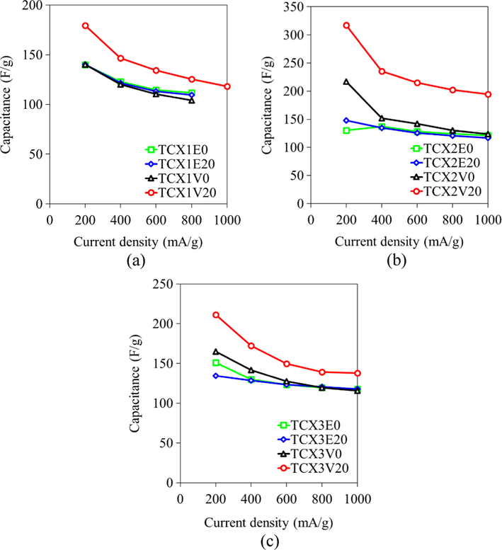
Influence of current densities on capacitances values of TCXs prepared by various synthesis conditions and drying methods: (a) TCX1s, (b) TCX2s and (c) TCX3s. Reprinted with permission from Ref. (Kraiwattanawong, 2020).
Yang et al. studied the electronic and ionic resistance throughout the pore size of carbon aerogels (Yang et al., 2017). The pore size was found to be the key factor that determined the electrochemical behavior of the EDLC electrode. The large pore size of carbon aerogels provided low ionic resistance, while the small pore size with a dense structure of carbon aerogels contributed to low electronic resistance. The ordered mesoporous carbon gave higher capacitances than the disordered mesoporous carbon (Matsui et al., 2013). The straight channels and their length acted as ion-highways leading to excellent capacitance and rate performance (Kraiwattanawong, 2020; Matsui et al., 2013). The mass transfer resistance could be diminished by decreasing the particle size and the high mono-dispersity of carbon spheres promoting the overall EDLC performance (Tanaka et al., 2012). The capacitance not only relied on the surface area, but it also depended on the pore size distribution (Zhang et al., 2010). The broad pore size distribution allowed low ion resistance. The (C2H5)4NBF4/PC electrolyte preferred the pore size of 2–3 nm. Powdery carbon aerogels avoided inaccessible pore which increased the surface area by about 2,052 m2 g−1 with 384F g−1 (Xu et al., 2017). The micropores of TF carbon cryogel clearly determined the capacitance at low and high scan rates (Amaral-Labat et al., 2012). Zeller et al. studied the effect of electrolyte type on capacitance (Zeller et al., 2012). The type of electrolyte used also determined the pore structure of porous carbon materials. The capacitance of an organic electrolyte could be limited at the external surface because the organic electrolyte could not enter the micropore. The capacitance of an aqueous electrolyte was merely dependent on the total surface area. Fang et al. modified the surface of activated carbon with oleate providing the superior capacitance due to the good wettability of the organic electrolyte (Fang et al., 2005).
Centeno’s group assessed the surface capacitance using the (C2H5)4NBF4/AN electrolyte and various microporous carbons (Centeno et al., 2011; Garcia-Gomez et al., 2015; Lobato et al., 2017). The BET surface area could underestimate for the micropores below 0.8 nm and overestimate for the micropores above 1.1 nm. They recommended replacing the BET surface area with the total surface area calculated by the non-local density functional theory (Garcia-Gomez et al., 2015). The surface capacitance became constant about 0.094 ± 0.011F m−2 for (C2H5)4NBF4/AN for the organic electrolyte. The combination of carbon surface by the CO2 and N2 probe molecules in the D-R plots assessed around 0.10F m−2 for the organic (C2H5)4NBF4/AN and aqueous H2SO4 electrolytes (Lobato et al., 2017). With the 2D materials (graphene-based carbons), the surface-capacitance assessment was not defined well (Lobato et al., 2017). Yet the surface-capacitance assessment is a promising study for the modelling materials.
5 Summary and outlook
Energy storage devices require a carbon electrode with a suitable pore structure and high surface area. The carbon gels and their derivatives provide the micropores and mesopores naturally through methodical synthesis and suitable recipes. The micropores enhance ion storage capacity, whereas the mesopores and macropores decrease ion resistance. The carbon gels also allow the designable carbon electrode in the various shapes and the porous properties. Many research works continuously synthesize porous carbons as the model materials to reinforce electrochemical performance, despite nearly identical surface area. It is undoubtable that the carbon electrodes are responding to develop superior pore structure and high surface area to suit the electrolyte used in the energy storage devices and they are applied as model materials to study electrochemical behaviors.
Carbon-based networks as the asymmetric-capacitor electrode with metal ion loading on the carbon substrate performs the great electrochemical in the redox reaction (Kumar et al., 2021). Some electrodes based on carbon nanotubes retain their capacitance more than 90% with their cycle life over 1.000 cycles. The others deviate depending on the carbon bases, the metal, and the preparation method. The carbon nanomaterials can improve the overall performance of capacitors by the different dimensions (0D, 1D, 2D and 3D) and pseudocapacitive materials in asymmetric design. The insertion of different dimensional carbon nanomaterials reinforces the specific capacitance of asymmetric-capacitor devices. Yet the ion transport and the sluggish redox kinetics limits the cyclic behavior and the power density of asymmetric capacitors. The nanomaterial design such as doping, core–shell design, hierarchical structure, highly porous architecture, and multi-metal centers are needed to reduce the limitation. The high surface area of carbon nanomaterials with excellent conductivity and good mechanical properties are required for asymmetric-capacitor devices. The 3D carbon network with the high interstitial surface area is also preferred by the interconnected pore structure allowing the appropriate charge pathway. For the high frequency response applications, the sub-micron thin film structure is required for the 2D substrate, and the large pore volume is necessary for the 3D current collector (Fan et al., 2017).
The simulation is a promising work both the equilibrium and the dynamic study. (Tao et al., 2020; Yang et al., 2020; Lian et al., 2020). Especially the dynamic study, the nonequilibrium is frequently difficult to investigate or design the experiment. The longer neutral-chain-electrolyte structure in the porous electrode revealed the high surface capacitance (Yang et al., 2020). The dynamic charging response is a considerate study to understand the ion-transport behavior in the capacitor. Recently, Lian et al. reviewed the simple stack-electrode model corresponding the parameters of capacitor configuration (Lian et al., 2020). This model is well predicted the charging time and needs the improvement. Therefore, the nanoporous-carbon preparation as the modeling materials suiting the equivalent-circuit model is a promising study to understand the dynamic efficiency of capacitors and develop the equivalent-circuit model. The simulation can contribute the theory but require the proof of work. The porous carbon-based as modeling materials can support the electrochemical theory.
For the further outlook, the high porosity, the short-time and low-cost production, the electrochemically promoted pore structure, and the low electric resistance of carbon gels are desirable for developing the high performance of carbon gels. The bioresource materials render low-cost production whereas the carbon-gel processing must be suitably modified. The form of carbon gels must be designed from 0D to 3D depended on the applications. Non-uniform structure might permit the new structure such as the sponge-like carbon xerogels supporting the electrochemical behavior. The surface capacitance is a promising study for the modelling materials. The size reduction as powdery carbon gels increase the specific surface area. Therefore, the thin layer and 3D carbon gels might have the high specific surface area supporting the electrochemical performance in the gravimetric, aerial and volumetric capacity.
Funding
This research was financially supported by the Thailand Research Fund (Grant No. RSA5980004), and King Mongkut’s Institute of Technology Ladkrabang Research Fund (Grant No. 2564-02-01-004).
Institutional review board statement
Not applicable.
Informed consent statement
Not applicable.
Data availability statement
The data presented in this study are available on request from the corresponding author.
CRediT authorship contribution statement
Kriangsak Kraiwattanawong: Conceptualization, Writing – original draft, Writing – review & editing.
Declaration of Competing Interest
The authors declare that they have no known competing financial interests or personal relationships that could have appeared to influence the work reported in this paper.
References
- Preparation and properties of resorcinol-formaldehyde organic and carbon gels. Adv. Mater.. 2003;15:101-114.
- [CrossRef] [Google Scholar]
- Pore structure and electrochemical performances of tannin-based carbon cryogels. Biomass Bioenergy. 2012;39:274-282.
- [CrossRef] [Google Scholar]
- Babic, B., Kaluderovic, B., Vracar, Lj., Krstajic, N., 2004. Characterization of carbon cryogel synthesized by sol–gel polycondensation and freeze-drying. Carbon 42, 2617-2624. https://doi.org/10.1016/j.carbon.2004.05.046.
- Progress in bioethanol processing. Prog. Energy Combus. Sci.. 2008;34:551-573.
- [CrossRef] [Google Scholar]
- Capacitance in carbon pores of 0.7 to 15 nm: a regular pattern. Phys. Chem. Chem. Phys.. 2011;13:12403-12406.
- [CrossRef] [Google Scholar]
- Preparation and enhanced supercapacitance performance of porous carbon spheres with a high degree of graphitization. RSC Adv.. 2015;5:2088-2095.
- [CrossRef] [Google Scholar]
- Ensiling agricultural residues for bioethanol production. Appl. Biochem. Biotechnol.. 2007;143:80-92.
- [CrossRef] [Google Scholar]
- Influence of drying on the morphology of resorcinol–formaldehyde-based carbon gels. Micropor. Mesopor. Mater.. 2005;86:124-133.
- [CrossRef] [Google Scholar]
- Progress and recent trends in biofuels. Prog. Energy Combus. Sci.. 2007;33:1-18.
- [CrossRef] [Google Scholar]
- 3D network of cellulose-based energy storage devices and related emerging applications. Mater. Horiz.. 2017;4:522-545.
- [CrossRef] [Google Scholar]
- Towards kilohertz electrochemical capacitors for filtering and pulse energy harvesting. Nano Energy. 2017;39:306-320.
- [CrossRef] [Google Scholar]
- High capacity supercapacitors based on modified activated carbon aerogel. J. Appl. Electrochem.. 2005;35:229-233.
- [CrossRef] [Google Scholar]
- Feaver, A.M., Cao, G., 2010. Electric double layer capacitance device, U.S. Patent 7835136, 16 Nov..
- Carbon materials for supercapacitor application. Phys. Chem. Chem. Phys.. 2007;9:1774-1785.
- [CrossRef] [Google Scholar]
- Carbon materials for the electrochemical storage of energy in capacitors. Carbon. 2001;39:937-950.
- [CrossRef] [Google Scholar]
- Fabrication of activated carbon fibers/carbon aerogels composites by gelation and supercritical drying in isopropanol. J. Mater. Res.. 2003;18:2765-2773.
- [CrossRef] [Google Scholar]
- High-surface area carbons from renewable sources with a bimodal micro-mesoporosity for high performance ionic liquid-based supercapacitors. Carbon. 2015;94:41-52.
- [CrossRef] [Google Scholar]
- Studies and characterization of various activated carbons used for carbon/carbon supercapacitors. J. Power Sources. 2001;101:109-116.
- [CrossRef] [Google Scholar]
- Constant capacitance in nanopores of carbon monoliths. Phys. Chem. Chem. Phys.. 2015;17:15687-15690.
- [CrossRef] [Google Scholar]
- Study of correlation of structural and surface properties with electrochemical behaviour in carbon aerogels. J. Mater. Sci.. 2005;40:3777-3782.
- [CrossRef] [Google Scholar]
- Hirahara, S., Takeda, Y., Toki, K., 2006. Activated carbon for use in electric double layer capactors. U.S. Patent 7091156, 15 Aug.
- Influence of surface-active agents on pore characteristics of the generated spherical resorcinol-formaldehyde based carbon aerogels. Carbon. 2004;42:2683-2689.
- [CrossRef] [Google Scholar]
- Preparation of nanoporous carbon particles and their cryogenic hydrogen storage capacities. J. Phys. Chem. C. 2008;112:1516-1523.
- [CrossRef] [Google Scholar]
- A universal model for nanoporous carbon supercapacitors applicable to diverse pore regimes, carbon materials, and electrolytes. Chem. Eur. J.. 2008;14:6614-6626.
- [CrossRef] [Google Scholar]
- Pores in carbon materials-importance of their control. New Carbon Mater.. 2009;24:193-222.
- [CrossRef] [Google Scholar]
- Carbon materials for electrochemical capacitors. J. Power Sources. 2010;195:7880-7903.
- [CrossRef] [Google Scholar]
- Activated carbons prepared by indirect and direct CO2 activation of lignocellulosic biomass for supercapacitor electrodes. Renew. Energy. 2020;155:38-52.
- [CrossRef] [Google Scholar]
- Porous carbon xerogels with texture tailored by pH control during sol–gel process. Carbon. 2004;42:619-628.
- [CrossRef] [Google Scholar]
- Carbon aerogels, cryogels and xerogels: influence of the drying method on the textural properties of porous carbon materials. Carbon. 2005;43:2481-2492.
- [CrossRef] [Google Scholar]
- Towards the production of carbon xerogel monoliths by optimizing convective drying conditions. Carbon. 2006;44:2534-2542.
- [CrossRef] [Google Scholar]
- Preparation and sorption properties of porous materials from refuse paper and plastic fuel (RPF) J. Hazard Mater.. 2006;137:352-358.
- [CrossRef] [Google Scholar]
- Study of the structure-properties relations of carbon spheres affecting electrochemical performances of EDLCs. Electrochim. Acta. 2019;304:210-220.
- [CrossRef] [Google Scholar]
- Cellulose: fascinating biopolymer and sustainable raw material. Angew. Chem. Int. Ed.. 2005;44:3358-3393.
- [CrossRef] [Google Scholar]
- Texture control of freeze-dried resorcinol–formaldehyde gels. J. Non-Cryst. Solids. 1998;225:8-13.
- [CrossRef] [Google Scholar]
- Metal-organic framework (MOF)-derived catalysts for fine chemical production. Coord. Chem. Rev.. 2020;416:213319
- [CrossRef] [Google Scholar]
- Improvement of the textural properties of templated carbon xerogels using cotton fibres as a hard template dehydrated by sulphuric acid. Diam. Relat. Mater.. 2019;92:9-17.
- [CrossRef] [Google Scholar]
- Macropore-assisted electrolyte transfer inside binder-free templated carbon xerogels as carbon electrode for electric double layer capacitors. Eur. Polym. J.. 2020;130:109678
- [CrossRef] [Google Scholar]
- Influence of solvent species used in solvent exchange for preparation of mesoporous carbon xerogels from resorcinol and formaldehyde via subcritical drying. Micropor. Mesopor. Mater.. 2011;138:8-16.
- [CrossRef] [Google Scholar]
- Low-cost production of mesoporous carbon/carbon composite cryogels. Carbon. 2011;49:3404-3411.
- [CrossRef] [Google Scholar]
- Carbon tunnels formed in carbon/carbon composite cryogels. Micropor. Mesopor. Mater.. 2012;153:47-54.
- [CrossRef] [Google Scholar]
- Capacitive performance of binder-free carbon/carbon composite cryogels. Micropor. Mesopor. Mater.. 2013;165:228-233.
- [CrossRef] [Google Scholar]
- 0D to 3D carbon-based networks combined with pseudocapacitive electrode material for high energy density supercapacitor: A review. Chem. Eng. J.. 2021;403:126352
- [CrossRef] [Google Scholar]
- Blessing and curse: How a supercapacitor’s large capacitance causes its slow charging. Phys. Rev. Lett.. 2020;124:076001
- [CrossRef] [Google Scholar]
- Effect of synthesis pH on the structure of carbon xerogels. Carbon. 1997;35:1271-1278.
- [CrossRef] [Google Scholar]
- Correlation of double-layer capacitance with the pore structure of sol-gel derived carbon xerogels. J. Electrochem. Soc.. 1999;146:3639-3643.
- [CrossRef] [Google Scholar]
- Carbon activation by alkaline hydroxides preparation and reactions, porosity and performance. CRC Press Florida 2007:1-62.
- [Google Scholar]
- Capacitance and surface of carbons in supercapacitors. Carbon. 2017;122:434-445.
- [CrossRef] [Google Scholar]
- Freeze-dried resorcinol-formaldehyde gels. J. Non-Cryst. Solids. 1997;212:250-261.
- [CrossRef] [Google Scholar]
- The effect of surfactants on the porosity of carbon xerogels. Microporous Mesoporous Mater.. 2006;92:38-46.
- [CrossRef] [Google Scholar]
- Recent progress in the development of biomass-derived nitrogen-doped porous carbon. J. Mater. Chem. A. 2021;9:3703-3728.
- [CrossRef] [Google Scholar]
- Correlation between the capacitor performance and pore structure of ordered mesoporous carbons. Adv. Powder Technol.. 2013;24:737-742.
- [CrossRef] [Google Scholar]
- Mayer, S.T., Kaschmitter, J., Pekala, R.W., 1995. Method of low pressure and/or evaporative drying of aerogels, U.S. Patent 5420168, 30 May.
- Facile synthesis of nanoporous carbons with high surface area and their CO2 adsorption properties. Chem. Lett.. 2015;44:1004-1006.
- [CrossRef] [Google Scholar]
- Miyairi, M., 1995. Electric double-layer capacitor. Eur. Patent 0680061A1, 2 Nov.
- Colloidal crystal-templated porous carbon as a high performance electrical double-Layer capacitor material. Electrochem. Solid-State Lett.. 2004;7:A221-A223.
- [CrossRef] [Google Scholar]
- Monodispersed nanoporous starburst carbon spheres and their three-dimensionally ordered arrays. Micropor. Mesopor. Mater.. 2009;117:478-485.
- [CrossRef] [Google Scholar]
- Capacitors consisting of an aqueous electrolyte of the widest potential window —development towards the recovery of regenerating energy of automobiles. Electrochemistry. 2020;88:99-106.
- [CrossRef] [Google Scholar]
- Organic aerogels from the polycondensation of resorcinol with formaldehyde. J. Mater. Sci.. 1989;24:3221-3227.
- [CrossRef] [Google Scholar]
- Structure of organic aerogels. 1. Morphology and scaling. Macromolecules. 1993;26:5487-5493.
- [CrossRef] [Google Scholar]
- Aerogels derived from multifunctional organic monomers. J. Non-Cryst. Solids. 1992;145:90-98.
- [CrossRef] [Google Scholar]
- Planar fibre reinforced carbon aerogels for application in PEM fuel cells. Carbon. 2001;39:857-867.
- [CrossRef] [Google Scholar]
- Preparation of activated carbon nanofibers using degradative solvent extraction products obtained from low-rank coal and their utilization in supercapacitors. RSC Adv.. 2020;10:8172-8180.
- [CrossRef] [Google Scholar]
- Qu, D., Shi, H., 1998. Studies of activated carbons used in double-layer capacitors, J. Power Sources, 74 (1998) 99-107. https://doi.org/10.1016/S0378-7753(98)00038-X.
- Relationship between the nanoporous texture of activated carbons and their capacitance properties in different electrolytes. Carbon. 2006;44:2498-2507.
- [CrossRef] [Google Scholar]
- Carbon cloth-reinforced and activated aerogel films for supercapacitors. J. Non-Cryst Solids. 2001;285:277-282.
- [CrossRef] [Google Scholar]
- Self-buffered pH at carbon surface in aqueous supercapacitor. Carbon. 2018;129:758-765.
- [CrossRef] [Google Scholar]
- Porous structure of organic and carbon aerogels synthesized by sol-gel polycondensation of resorcinol with formaldehyde. Carbon. 1997;35:791-796.
- [CrossRef] [Google Scholar]
- Control of mesoporous structure of organic and carbon aerogels. Carbon. 1998;36:1257-1262.
- [CrossRef] [Google Scholar]
- Preparation of mesoporous carbon by freeze drying. Carbon. 1999;37:2049-2055.
- [CrossRef] [Google Scholar]
- Influence of freeze-drying conditions on the mesoporosity of organic gels as carbon precursors. Carbon. 2000;38:1099-1105.
- [CrossRef] [Google Scholar]
- Freeze drying for preparation of aerogel-like carbon. Drying Technol.. 2001;19:313-324.
- [CrossRef] [Google Scholar]
- An experimental investigation of the ion storage/transfer behavior in an electrical double-layer capacitor by using monodisperse carbon spheres with microporous structure. J. Phys. Chem. C. 2012;116:26791-26799.
- [CrossRef] [Google Scholar]
- Multiscale modeling of electrolytes in porous electrode: from equilibrium structure to non-equilibrium transport, Green. Energy Environ.. 2020;5:303-321.
- [CrossRef] [Google Scholar]
- Binderfree synthesis of high-surface-area carbon electrodes via CO2 activation of resorcinol–formaldehyde carbon xerogel disks: Analysis of activation process. Carbon. 2014;76:240-249.
- [CrossRef] [Google Scholar]
- Synthesis of uniform mesoporous carbon capsules by carbonization of organosilica nanospheres. Chem. Mater.. 2010;22:2526-2533.
- [CrossRef] [Google Scholar]
- Carbon cloth reinforced carbon aerogel films derived from resorcinol formaldehyde. J. Porous Mater.. 2001;8:159-165.
- [CrossRef] [Google Scholar]
- Synthesis of hierarchically porous carbon spheres with yolk-shell structure for high performance supercapacitors. Catal. Today. 2015;243:199-208.
- [CrossRef] [Google Scholar]
- Confined self-assembly in two-dimensional interlayer space: Monolayered mesoporous carbon nanosheets with in-plane orderly arranged mesopores and a highly graphitized framework. Angew. Chem. Int. Ed.. 2018;57:2894-2898.
- [CrossRef] [Google Scholar]
- Accelerating the synthesis of carbon aerogel precursors. J. Non-Cryst. Solids. 2004;350:126-130.
- [CrossRef] [Google Scholar]
- Preparation of low-density carbon aerogels by ambient pressure drying. Carbon. 2004;42:2033-2039.
- [CrossRef] [Google Scholar]
- Fabrication of novel powdery carbon aerogels with high surface areas for superior energy storage. Energy Storage Mater.. 2017;7:8-16.
- [CrossRef] [Google Scholar]
- Agricultural bio-waste materials as potential sustainable precursors used for activated carbon production: A review. Renew. Sust. Energy Rev.. 2015;46:218-235.
- [CrossRef] [Google Scholar]
- Effect of drying method on mesoporosity of resorcinol-formaldehyde drygel and carbon gel. Drying Technol.. 2001;19:1319-1333.
- [CrossRef] [Google Scholar]
- Control of mesoporosity of carbon gels prepared by sol-gel polycondensation and freeze drying. J. Non-Cryst. Solids. 2001;288:46-55.
- [CrossRef] [Google Scholar]
- Preparation and characterization of carbon cryogel microspheres. Carbon. 2002;40:1345-1351.
- [CrossRef] [Google Scholar]
- Relationships between pore size and charge transfer resistance of carbon aerogels for organic electric double-layer capacitor electrodes. Electrochim. Acta. 2017;223:21-30.
- [CrossRef] [Google Scholar]
- Chain length matters: Structural transition and capacitance of room temperature ionic liquids in nanoporous electrodes. Chem. Eng. Sci.. 2020;227:115927
- [CrossRef] [Google Scholar]
- Yoshida, A., Nishino, A., Takeuchi, I., 1986. Electric double layer capacitor and method for producing the same. U.S. Patent 4597028, 14 Jun.
- Solvent-free synthesis and KOH activation of mesoporous carbons using resorcinol/Pluronic F127/hexamethylenetetramine mixture and their application to EDLC. Micropor. Mesopor. Mat.. 2018;272:217-221.
- [CrossRef] [Google Scholar]
- Relationship between structural properties and electrochemical characteristics of monolithic carbon xerogel-based electrochemical double-layer electrodes in aqueous and organic electrolytes. Adv. Energy Mater.. 2012;2:598-605.
- [CrossRef] [Google Scholar]
- Effect of pore structure on the electrochemical performance of coal-based activated carbons in non-aqueous electrolyte. New Carbon Mater.. 2010;25:129-133.
- [CrossRef] [Google Scholar]
- Carbon-based materials as supercapacitor electrodes. Chem. Soc. Rev.. 2009;38:2520-2531.
- [CrossRef] [Google Scholar]
- Development of microporous carbon xerogels by controlling synthesis conditions. J. Non-Cryst. Solids. 2008;354:817-825.
- [CrossRef] [Google Scholar]


