

Translate this page into:
Characterizations of nickel mesh and nickel foam current collectors for supercapacitor application
⁎Corresponding author. aam@usm.my (Ahmad Azmin Mohamad)
-
Received: ,
Accepted: ,
This article was originally published by Elsevier and was migrated to Scientific Scholar after the change of Publisher.
Peer review under responsibility of King Saud University.
Abstract
Nickel (Ni) current collectors having a three-dimensional and porous structure are considered attractive contestants for high-efficiency supercapacitors. Therefore, Ni current collectors have a unique architecture and outstanding electrochemical properties. This study reports the effect of electrochemical characterizations on the electrochemical behavior and physical properties of Ni mesh and Ni foam. Cyclic voltammetry (CV) and galvanostatic charge discharge (GCD) are used to examine the electrochemical properties and life span of the Ni mesh and Ni foam as a current collector in a supercapacitor application. Structural and microstructural characterizations are performed to verify the formation of an oxide layer after 1000 cycles of CV analysis. Results show that Ni foam can increase the yield electrochemical performance of the supercapacitor. Ni foam present better efficiency (35 F g−1) compared to the Ni mesh (12 F g−1) at 10 mV s−1 scan rate by using 2 mg imaginary mass of active material. This result shows that Ni foam has good electrochemical performance and reversibility, higher pseudocapacitance, weaker polarization, and enhance rotating performance as to Ni mesh. The porous structure of Ni foam is in control for improving of the electrochemical properties, therefore, the electrochemical region was increased and shortened ion diffusion. Structural analysis shows that Ni mesh and Ni foam are oxidized after the electrochemical analysis and transformed to nickel oxide hydroxide (NiOOH). Higher specific surface area between the electrode and electrolyte leads to excellent electrochemical and pseudocapacitive performance of the Ni foam compared to the Ni mesh, even if the materials of current collectors are the same. Hence, the physical structure of the current collectors have a critical part in improving the energy density of the supercapacitor.
Keywords
Supercapacitor
Nickel foam
Nickel mesh
Redox reaction
Cyclic voltammetry

1 Introduction
The rapid development of the electronics industry has increased the demands for corresponding electrical storage. Among various energy storages, supercapacitors have been extensively commercialized because of their high power performance, elongated cycle life, high capacitance densities and environmental friendliness (Huang et al., 2018; Li et al., 2017; Marina et al., 2019; Xing et al., 2011; Zhang et al., 2017; Zhou et al., 2019). A symmetric supercapacitor contains of an anode and a cathode, disconnected by a separator and immersed in an electrolyte. All the components have important roles in the supercapacitor’s electrochemical performance. Both electrodes are composed of four main components: active material, conductive filler, binder and current collector. The current collector acts as the power link between the supercapacitor’s active material and its external terminals. The electrochemical process occurs on the surface of the active material. Therefore, a supercapacitor requires highly effective current collectors, which must provide good electrical contact with the active material (Kovalenko et al., 2018; Wang et al., 2019). Additionally, there are important demands as regards the specific surface area, crystal structure and electrochemical activity of the current collectors of such electrodes.
A three-dimensional (3D) porous nanostructure of current collectors can afford large contact areas and reduced ionic diffusion distances as well as promote the separation and transport of charges (Jing et al., 2020b; Khezri et al., 2020; Liu et al., 2018; Xing et al., 2011; Yuan et al., 2011; Zhang et al., 2019; Zhao et al., 2017). Especially, current collectors having a high specific surface area can enlarge the active material–electrolyte interfaces. Moreover, nanostructured current collectors with a fair design and minimize contact resistance can dramatically enhance the transport characteristics of ions and all charge carriers (Pilathottathil et al., 2019; Zhou et al., 2010). Spread resistance can influence the interface between the two electrical items, so that equal series resistance will greatly increase the transport characteristic of both charge carriers and ions. Most existing current collectors that are used in supercapacitors are copper (Cu) (Madito et al., 2020; Su et al., 2019), stainless steel (Özdemir et al., 2019; Yanuar et al., 2019), aluminum (Al) (Kavian et al., 2011), and nickel (Ni) (Kovalenko et al., 2018; Liang et al., 2019; Xing et al., 2011; Yuan et al., 2011). These current collectors must have ideal conductivity, good level of temperature, the long-term safety of chemical product, high resistance to corrosion and huge surface areas per unit volume and mass.
Ni as a current collector is used accordingly, having different types such as mesh, wire, and foam. Ni foam has high porosity structure with an interlinked 3D scaffold of Ni metal, possessing particular features i.e. light material, high porosity, built-in strength, high resistance to corrosion, and favorable electrical and thermal conductivity (Yu et al., 2014). Therefore, Ni foam has attracted substantial attention as a current collector or template for built-up 3D electrodes. A previous study reported a porous β-Ni(OH)2/γ-NiOOH composite film that was prepared using a chemical bath deposition process that reveals an extremely porous net structure with a thickness of 20–25 nm. This composite film exhibited higher pseudocapacitance (1420 Fg−1 at 2 Ag−1 and 1098 Fg−1 at 40 Ag−1) than the dense nickel hydroxide (Ni(OH)2) film (897 Fg−1 at 2 Ag−1 and 401 at 40 Ag−1) (Yuan et al., 2011). The capacitance of Ni(OH)2 reached up to 3152 Fg−1 when the Ni foam was used as a current collector (Yang et al., 2008). Since most of the papers reporting very high capacitance value when using nickel foam as current collectors, it is quite indispensable to evaluate in detail these current collectors (Gao et al., 2010; Hu et al., 2010; Liu et al., 2019; Peng et al., 2019; Yu et al., 2020; Zheng et al., 2018). This demonstrated that Ni foam as a current collector can improve the specific capacitance of the supercapacitor.
In this work, two types of the current collector (mesh and foam) are characterized in order to study the effects of different current collectors in supercapacitor. The electrochemical behavior of both current collectors are characterized by CV, GCD as well as specific capacitance. The degradation or conversion of current collectors after cycling is then characterized by structural and morphological analysis.
2 Experimental
Ni mesh (Exmet Corporation) and Ni foam (YITE Manufacturer, China) were sonicated in acetone solution for 10 min, washed with distilled water, and then dried in an oven at 80 °C for 2 h to remove the excess water. Electrochemical characterization, CV, GCD, and electrochemical impedance spectroscopy (EIS) were done in a three-electrode cell constructed with Ni foam and Ni mesh (1 × 1 cm2) as a working electrode (no active material weighted on this electrode), a platinum (Pt) counter electrode, and a mercury/mercury oxide (Hg/HgO) reference electrode in 1 M KOH (Sigma Aldrich) aqueous solution. A potential range of −0.1 to 0.7 V vs. Hg/HgO reference electrode was used for both CV and GCD analysis on Autolab potentiostat (PGSTAT302 N, Metrohm). Cyclic stability tests of Ni foam and Ni mesh were carried out up to 1000 cycles at a constant scan rate (10 mV s−1). EIS tests were then performed in the frequency range of 100 kHz–1 mHz. The specific capacitance of the electrode was calculated from CV curves by:
X-ray diffraction technique (XRD, Bruker Advanced X-ray Solutions D9) in the 2θ window from 10° to 90° with monochromatized Cu Kα radiation (λ = 1.5406 Å) was used to characterize the structural properties. Rietveld refinement was executed on the XRD data using X’Pert High Score Plus software to access the parameters of the structure. Using field-emission scanning electron microscope (FESEM, Zeiss SupraTM, 35VP), and energy-dispersive X-ray spectroscopy (EDX), surface morphology and elemental analysis of Ni mesh and Ni foam were examined.
3 Results and discussion
3.1 Electrochemical analysis of current collectors
The fresh Ni mesh and Ni foam with an aperture diameter of 1.438 mm and 0.785–0.233 mm have typical silvery metallic, smooth, and clean surfaces (Fig. 1a and b). Surface morphologies of the fresh Ni mesh and Ni foam were investigated by FESEM at 50x magnification (Fig. 1c and d). By observation, Ni mesh has a layer of cross-linked structure, while Ni foam showed a 3D porous, cross-linked structure. In addition, the diameter (hole and strand) of Ni foam is smaller than that of Ni mesh. Ni foam has a larger surface area compared to the Ni mesh due to its porous structure. The larger surface area can lead to an increase in charge transfer, higher pseudocapacitance properties, and can lower the blocking between the active material and electrolyte (Liang et al., 2019; Xie et al., 2019; Xing et al., 2011; Yuan et al., 2011). From the picture it is clear that the Ni foam surface can be covered with tiny and large particles with a 3D structure that covers a relatively broad surface area.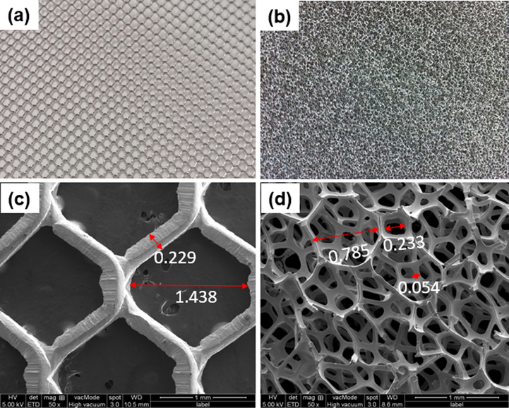
Pictures of fresh (a) Ni mesh (b) Ni foam (c) FESEM images of fresh Ni mesh and (d) Ni foam at 50x magnification.
The effects of two different physical forms of Ni as current collectors (Ni mesh and Ni foam) during the electrochemical process were characterized by CV (Fig. 2a). In the first cycle, Ni mesh exhibits one redox pair: an oxidation (0.53 V) and a reduction (0.45 V); Ni foam also exhibits an oxidation (0.55 V) and a reduction (0.46 V) (Fig. 2b). These peaks are generally connected to a Faradaic reaction of Ni(OH)2 (Xing et al., 2011) as in Eq. (2):
Ni(OH)2 + OH−↔NiOOH + H2O + e−(2)
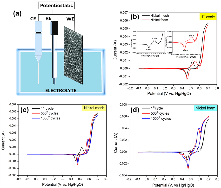
(a) Graphical setup for electrochemical characterization (b) CV curves of Ni mesh and Ni foam at first cycle (c) CV curves of Ni mesh at 1000 cycles and (d) CV curves of Ni foam at 1000 cycles at 10 mV s−1 in potential window of −0.1 to 0.7 V vs. Hg/HgO in 1 M KOH solution.
Ni foam has higher oxidation and reduction potentials compared to Ni mesh. Yet, Ni foam exhibits higher potential separation (0.09 V) compared to Ni mesh (0.08 V). The peak potential separation is used to evaluate reversibility. The result indicated that both Ni foam and Ni mesh show excellent electrochemical action and reversible reaction; and the difference between Ni mesh and Ni foam was merely 0.01 V.
After 500 cycles, the main oxidation peak (0.59 V) and reduction peak (0.47 V) for both current collectors shifted to higher potentials (Fig. 2c and d). The shift was caused by the nonstoichiometric property of the electrochemically active Ni(OH)2 and NiOOH phases (Xing et al., 2011). In this work, the redox couples that appeared at 500 until 1000 cycles in Ni mesh (0.6 V/0.48 V) and Ni foam (0.59 V/0.48 V) contributed to the transformation between β-Ni(OH)2 and β-NiOOH. In addition, the redox couples (0.55 V/0.43 V) in Ni foam correspond to change between α-Ni(OH)2 and γ-NiOOH (Xing et al., 2011). There is not much difference between the 500 and 1000 cycles, proposing that the transition happens mostly in the first 500 cycles on the surface of Ni mesh and Ni foam.
In order to determine the effect of current collectors on specific capacitance, the specific capacitance was calculated with an imaginary 2 mg of active material based on (Eq. (1)) (Fig. 3). The imaginary weight was used because to know how the effect of current collector to the specific capacitance of active materials when it is used as current collectors. Ni foam exhibits higher specific capacitance, better capacitance retention and good cycling stability compared to Ni mesh (Fig. 3a). For the first 150 cycles, the specific capacitance of Ni mesh (Fig. 3b) and Ni foam (Fig. 3c) increased. In this case, the rise in specific capacitance is mostly correlated with the activation of the Ni(OH)2 structure, which accepts trapped ions in the crystalline structure of Ni(OH)2 (Yuan et al., 2011). After the first 150 cycles, the specific capacitance of Ni mesh fluctuated, as cycles increased. However, the specific capacitance for Ni foam remained constant (35 F g−1) and dropped slowly (33 F g−1) as cycles increased. Ni foam's porous nature gave it more benefit compared to Ni mesh as it can ease the stress induced by the increase in volume change, resulting in good cycling performance (Yuan et al., 2011). Then, it is noted that the specific capacitance of Ni mesh and Ni foam decreased very slightly as cycling numbers increased, it is due to the incremental transition of redox couples from α-Ni(OH)2/γ-NiOOH to β-Ni(OH)2/β-NiOOH.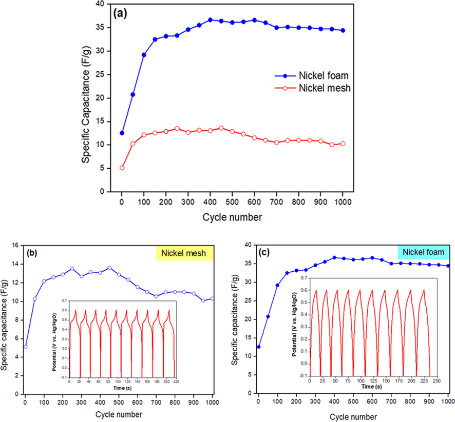
Comparison of specific capacitance of current collectors for 1000 cycles: (a) Ni mesh and Ni foam (b) Ni mesh (inset GCD curves for the first 10 cycles at 1 A g−1) and (c) Ni foam (inset GCD curves for the first 10 cycles at 1 A g−1).
To compare the CV with the discharge voltage plateau of discharge behavior, GCD was performed (inset Fig. 3b and c). The GCD curves of Ni mesh have a lower discharge voltage plateau compared to Ni foam. The discharge voltage plateau for both current collectors was found to be constant for the first ten cycles, as the electrodes have favorable electrochemical reversibility and charge–discharge properties. Ni foam exhibits much higher specific capacitance (35 F g−1) than the Ni mesh (12 F g−1). The enrichment of pseudocapacitor performance due to the application of Ni foam that shortens the diffusion passage for electrons and ions, resulting to faster kinetics (Jing et al., 2020a; Xu et al., 2017; Yuan et al., 2011). In addition, the high surface area provided effective interaction between Ni foam and electrolyte, offering more effective electrochemical reaction sites compared to Ni mesh.
The transport kinetics and contact resistance, occurring at the interface between the current collectors and electrolyte, were investigated using EIS (Fig. 4). No spike was found in Nyquist plots (Fig. 4a). The difference of the slopes in the low-frequency region revealed that both current collectors have a very limited charge transfer resistance (Jiang et al., 2015). The slope at lower frequency region for Ni foam was lower than Ni mesh, indicating that the porous Ni foam has much larger active reaction surface area than the dense Ni mesh. In the high-frequency region, the equivalent series resistance (Rs) was different for Ni mesh (4.14 Ω) and Ni foam (5.87 Ω) (Fig. 4b and c). In this case, Rs is determined by the contact resistance at the interface between current collector (Ni mesh and Ni foam) and electrolyte, the intrinsic resistance of the current collectors and ionic resistance of the electrolyte. The minimum Rs values indicated that the inner resistance of the electrode was insignificantly low, taking advantage of the greatly conductive current collectors. In this case, Ni foam exhibits higher Rs value due to the higher surface area and the thinner strand compared to Ni mesh. It suggesting that the higher surface area of nickel foam decrease the ion transport in the KOH electrolyte, obstruct the charge transport at the interface between electrolyte and electrode, and deteriorate the diffusion or transportation of electrolyte ions to the surface of electrode (Fan et al., 2020). Since both current collectors have the same structure, then the distinction in their internal resistances is not necessary.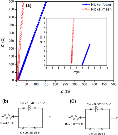
EIS analysis of both current collectors in 1 M KOH solution: (a) Nyquist plots and equivalent circuits of (b) Ni mesh and (c) Ni foam.
3.2 Structural and Rietveld refinement analysis
The phases of both current collectors before and after 1000 cycles of CV were investigated using XRD (Fig. 5). It is observed that Ni mesh and Ni foam (both states) contain only Ni planes at the diffraction peaks, 2θ = 44.34° (1 1 1), 51.54° (2 0 0), and 76.09° (2 2 0) (Fig. 5a and b). XRD analysis showed Ni is the major composition of Ni mesh and Ni foam, as no other peaks have been found. The development of the oxide layer (NiOOH) on the surface of the Ni mesh and Ni foam after 1000 cycles caused the intensity peaks of the Ni planes decreased. Since both Ni and NiOOH share the same peaks, it was very difficult to distinguish. Results from XRD analysis were in good agreement with the CV result for both current collectors.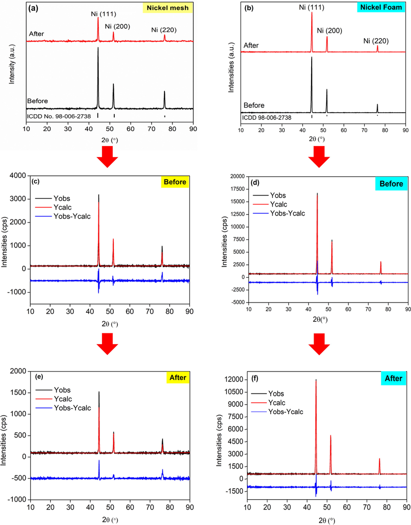
XRD patterns of (a) Ni mesh and (b) Ni foam. Observation and calculation of different profiles from Rietveld refinement of Ni mesh (c) before and (d) after and Ni foam (e) before and (f) after 1000 cycles of CV.
Rietveld refinement was conducted to quantitatively investigate the structural properties of Ni mesh and Ni foam before and after 1000 cycles of CV (Fig. 5c, d, e, and f). A good fit was obtained for all samples (Fig. 5). Only a small residue was contained, as dissipated in the difference plot (blue line). The goodness of fit (GoF) was 0.92389 (Ni mesh) and 1.84878 (Ni foam) before the cycle. After 1000 cycles, the GoF was reduced to 0.76332 (Ni mesh) and 0.79721 (Ni foam), which are considered good and acceptable (Table 1). As can be seen, the GoF values for all the samples were moderately low, around under 2%, which is considered as worthy as per the essential rule of the GoF under 4% and Rwp under 20% (Sarkar and Kannan, 2014). In addition, visual consequences of the plots show the achievement of the Rietveld refinement, as reflected by the little distinction among calculated and measured value (Fig. 5c, d, e, and f).
Parameter
Ni mesh (Before)
Ni mesh (After)
Ni foam (Before)
Ni foam (After)
Reference (ICDD:98-009-0200)
Ni Powder (Sakher et al., 2018)
Rwp
18.37166
17.56892
7.02156
7.76540
–
–
Rexp
17.65871
15.34964
9.54719
6.93346
–
–
GOF
0.92389
0.76332
1.84878
0.79721
–
1.5400
a (Å)
3.52703
3.52809
3.52292
3.525614
3.5230
3.5240
b (Å)
3.52703
3.52809
3.52292
3.525614
3.5230
3.5240
c (Å)
3.52703
3.52809
3.52292
3.525614
3.5230
3.5240
α (°)
90
90
90
90
90
90
β (°)
90
90
90
90
90
90
γ (°)
90
90
90
90
90
90
Regarding the refined data for fresh Ni mesh, the lattice parameters obtained were a = b = c = 3.52703 Å, and the lattice parameters of Ni mesh after 1000 cycles of CV were a = b = c = 3.52809 Å (Table 1). On the other hand, fresh Ni foam shows the lattice parameters obtained were a = b = c = 3.52292 Å and were then changed to a = b = c = 3.525614 Å after 1000 cycles of CV. Both lattice parameters of the current collectors were changed to only 0.03% from their original state and 0.11% when compared to Ni powder (Sakher et al., 2018). This shows that surface atoms on Ni mesh and Ni foam chemically responded with O2 and electrolyte to form Ni(OH)2 and NiOOH species, it also indicate that the supercapattery behavior of Ni mesh and Ni foam (as demonstrated by CV testing). However, the thickness of Ni(OH)2 and NiOOH layer is very thin and not compact to shield the Ni metal, which can be exposed by X-ray in the XRD characterization.
3.3 Morphology and elemental analysis
The surface morphologies and elemental analysis of current collectors were analyzed using SEM and EDX (Fig. 6). According to morphological analysis, Ni foam has a porous structure compared to Ni mesh. The large porosity and high surface area of Ni foam can enlarge the contact area between active material on the current collector and electrolyte, also shorten the ion diffusion path. Before CV characterization, Ni mesh and Ni foam (0.36 wt%) showed a smooth texture surface, while EDX analysis revealed very low percentage of oxygen (Fig. 6a and c). After 1000 cycles of CV, the surface of Ni mesh and Ni foam exhibited the formations of oxide layers (dark spots), indicating that redox reactions occurred (Fig. 6b and d). The formation of oxide layers was confirmed by EDX analysis, demonstrating the increasing weight percentage of the oxygen element on the surface of Ni mesh (5.90 wt%) and Ni foam (2.27 wt%). The presents of C and K mostly contributed from the electrolyte and impurities during the characterization process (Fig. 6b). These results were consistent with those of XRD, which is the transformation of Ni into NiOOH.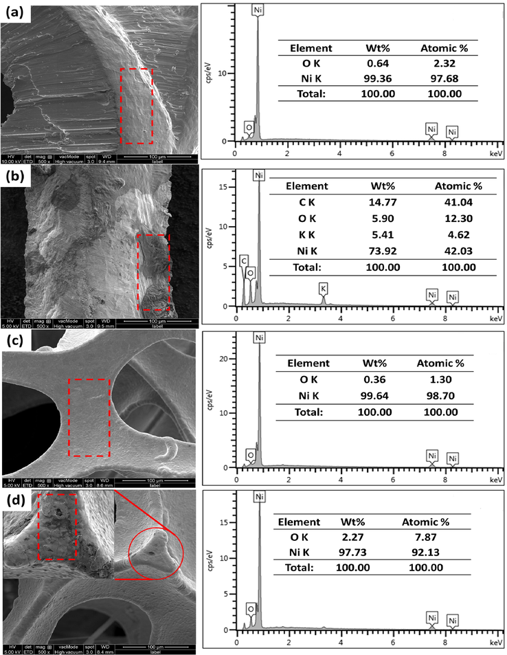
Morphologies and EDX analysis of current collectors: (a) fresh Ni mesh (b) Ni mesh after CV (c) fresh Ni foam and (d) Ni foam after CV with 1000 times cycle measurement.
4 Conclusion
In this work, Ni mesh and Ni foam were investigated for use as a current collector in a supercapacitor application. It is evident that Ni foam exhibited better electrochemical performance and reaction reversibility, higher pseudocapacitance, weaker polarization but better cycling performance compared to Ni mesh. Ni foam also exhibited good pseudocapacitive behavior (35 F g−1) compared to Ni mesh (12 F g−1) at 10 mV s−1 scan rate. Due to its high porosity and wide surface area, Ni foam demonstrated enhanced electrochemical performance, which increased the interaction between the electrolytes and active materials and shortened the direction of ion diffusion. Structural, morphological and elemental analyses confirm the transformation of Ni into NiOOH after electrochemical characterization. This result was in agreement with the CV result. Finally, the detailed physicochemical and electrochemical analyses revealed that the Ni foam current collector could efficiently increase charge transfer and minimize the resistance of the active material and current collector interface, thereby achieving high storage efficiency and high energy density.
CRediT authorship contribution statement
Nor Azmira Salleh: Writing - original draft, Methodology, Investigation, Visualization, Project administration. Soorathep Kheawhom: Writing - review & editing, Validation. Ahmad Azmin Mohamad: Supervision, Conceptualization, Writing - review & editing.
Acknowledgement
The authors would like to thanks the Universiti Sains Malaysia and appreciate the financial support provided by the RUI grant (Ref: USM-RUI 1010/PBAHAN/8014046).
Declaration of Competing Interest
The authors declare that they have no known competing financial interests or personal relationships that could have appeared to influence the work reported in this paper.
References
- Improved redox-active ionic liquid-based ionogel electrolyte by introducing carbon nanotubes for application in all-solid-state supercapacitors. Int. J. Hydrogen Energy 2020
- [Google Scholar]
- Electrochemical capacitance of Co3O4 nanowire arrays supported on nickel foam. J. Power Sources. 2010;195(6):1757-1760.
- [Google Scholar]
- Capacitance decay of nanoporous nickel hydroxide. J. Power Sources. 2010;195(19):6977-6981.
- [Google Scholar]
- Hierarchically mesostructured aluminum current collector for enhancing the performance of supercapacitors. ACS Appl. Mater. Interfaces. 2018;10(19):16572-16580.
- [Google Scholar]
- Hydrothermal synthesis of Ni (OH) 2 nanoflakes on 3D graphene foam for high-performance supercapacitors. Electrochim. Acta. 2015;173:399-407.
- [Google Scholar]
- Morphologically confined hybridization of tiny CoNi2S4 nanosheets into S, P co-doped graphene leading to enhanced pseudocapacitance and rate capability. Chem. Eng. J.. 2020;379:122305
- [Google Scholar]
- Optimizing the rate capability of nickel cobalt phosphide nanowires on graphene oxide by the outer/inter-component synergistic effects. J. Mater. Chem. A. 2020;8(4):1697-1708.
- [Google Scholar]
- Growth of carbon nanotubes on aluminium foil for supercapacitors electrodes. J. Mater. Sci.. 2011;46(5):1487-1493.
- [Google Scholar]
- Three-dimensional fibrous iron as anode current collector for rechargeable zinc-air batteries. Energies. 2020;13(6):1429.
- [Google Scholar]
- Kovalenko, V., Kotok, V., Kovalenko, I., 2018. Activation of the nickel foam as a current collector for application in supercapacitors. Bocтoчнo-Eвpoпeйcкий жypнaл пepeдoвыx тexнoлoгий (3 (12)), 56-62.
- Scalable self-propagating high-temperature synthesis of graphene for supercapacitors with superior power density and cyclic stability. Adv. Mater.. 2017;29(7):1604690.
- [Google Scholar]
- Enhanced capacitance characteristic of microporous carbon spheres through surface modification by oxygen-containing groups. Results Phys.. 2019;15:102586
- [Google Scholar]
- Evaluating the role of nanostructured current collectors in energy storage capability of supercapacitor electrodes with thick electroactive materials layers. Adv. Funct. Mater.. 2018;28(6):1705107.
- [Google Scholar]
- Nickel hydroxide/chemical vapor deposition-grown graphene/nickel hydroxide/nickel foam hybrid electrode for high performance supercapacitors. Electrochim. Acta. 2019;297:479-487.
- [Google Scholar]
- Nickel-copper graphene foam prepared by atmospheric pressure chemical vapour deposition for supercapacitor applications. Surf. Coat. Technol.. 2020;383:125230
- [Google Scholar]
- In situ growth of redox-active iron-centered nanoparticles on graphene sheets for specific capacitance enhancement. Arabian J. Chem.. 2019;12(8):3883-3889.
- [Google Scholar]
- Fabrication of nickel coating on a stainless steel mesh for supercapacitor applications. Çanakkale Onsekiz Mart Üniversitesi Fen Bilimleri Enstitüsü Dergisi. 2019;5(2):201-213.
- [Google Scholar]
- Crystal structure of nickel manganese-layered double hydroxide@ cobaltosic oxides on nickel foam towards high-performance supercapacitors. CrystEngComm. 2019;21(3):470-477.
- [Google Scholar]
- Role of a printed circuit board copper clad current collector in supercapacitor application. J. Electron. Mater.. 2019;48(9):5835-5842.
- [Google Scholar]
- Sakher, E., Loudjani, N., Benchiheub, M., Bououdina, M., 2018. Influence of milling time on structural and microstructural parameters of Ni50Ti50 prepared by mechanical alloying using Rietveld analysis. J. Nanomater. 2018.
- In situ synthesis, fabrication and Rietveld refinement of the hydroxyapatite/titania composite coatings on 316 L SS. Ceram. Int.. 2014;40(5):6453-6463.
- [Google Scholar]
- In-situ green synthesis of CuO on 3D submicron-porous/solid copper current collectors as excellent supercapacitor electrode material. J. Mater. Sci.: Mater. Electron.. 2019;30(4):3545-3551.
- [Google Scholar]
- In-situ grown manganese silicate from biomass-derived heteroatom-doped porous carbon for supercapacitors with high performance. J. Colloid Interface Sci.. 2019;534:142-155.
- [Google Scholar]
- Three-dimensional Ni/MnO2 nanocylinder array with high capacitance for supercapacitors. Results Phys.. 2019;12:1411-1416.
- [Google Scholar]
- Exaggerated capacitance using electrochemically active nickel foam as current collector in electrochemical measurement. J. Power Sources. 2011;196(8):4123-4127.
- [Google Scholar]
- Porous graphene oxide prepared on nickel foam by electrophoretic deposition and thermal reduction as high-performance supercapacitor electrodes. Materials. 2017;10(8):936.
- [Google Scholar]
- Electrodeposited nickel hydroxide on nickel foam with ultrahigh capacitance. Chem. Commun.. 2008;48:6537-6539.
- [Google Scholar]
- Yanuar, H., Asmi, S., Farma, R., Awitdrus, A., Taer, E., Mardhiansyah, M., 2019. Growth of Palladium Thin Film Deposited on Stainless Steel Current Electrodes by Wet Chemical Method for Actived Carbon Supercapacitor and Their Electrochemical Properties.
- Porous ultrathin NiSe nanosheet networks on nickel foam for high-performance hybrid supercapacitors. ChemSusChem. 2020;13(1):260-266.
- [Google Scholar]
- Scalable self-growth of Ni@ NiO core-shell electrode with ultrahigh capacitance and super-long cyclic stability for supercapacitors. NPG Asia Mater.. 2014;6(9) e129 e129
- [Google Scholar]
- Nickel foam-supported porous Ni (OH) 2/NiOOH composite film as advanced pseudocapacitor material. Electrochim. Acta. 2011;56(6):2627-2632.
- [Google Scholar]
- High performance lithium-ion hybrid capacitors employing Fe3O4–graphene composite anode and activated carbon cathode. ACS Appl. Mater. Interfaces. 2017;9(20):17136-17144.
- [Google Scholar]
- Cobalt-nickel silicate hydroxide on amorphous carbon derived from bamboo leaves for hybrid supercapacitors. Chem. Eng. J.. 2019;375:121938
- [Google Scholar]
- Three-dimensional Bi-continuous nanoporous gold/nickel foam supported MnO 2 for high performance supercapacitors. Sci. Rep.. 2017;7(1):1-8.
- [Google Scholar]
- Hydrothermal encapsulation of VO 2 (A) nanorods in amorphous carbon by carbonization of glucose for energy storage devices. Dalton Trans.. 2018;47(2):452-464.
- [Google Scholar]
- Green synthesis of nanoarchitectured nickel fabrics as high performance electrodes for supercapacitors. Renew. Energy. 2019;135:1445-1451.
- [Google Scholar]
- High-performance supercapacitors using a nanoporous current collector made from super-aligned carbon nanotubes. Nanotechnology. 2010;21(34):345701
- [Google Scholar]


