

Translate this page into:
Development and performance analysis of PEMFC stack based on bipolar plates fabricated employing different designs
⁎Corresponding author. Tel.: +20 1001074039 (mobile); fax: +20 2 33370931. kamelced@hotmail.com (K.M. El-Khatib) banimazar2003@yahoo.com (K.M. El-Khatib)
-
Received: ,
Accepted: ,
This article was originally published by Elsevier and was migrated to Scientific Scholar after the change of Publisher.
Peer review under responsibility of King Saud University.
Abstract
A low-temperature proton exchange membrane fuel cell (LT-PEMFC) is a promising clean and effective technology for power generation because of its simplified water and heat management. Due to the non-uniform of H2 and air distributions within fuel cells, the stack design is one of the key factors to enhance the performance and efficiency of LT-PEMFC. In this study, a single, two cells, 6 cells and 11 cells LT-PEMFC stack was investigated with cell active area 114 cm2, Nafion membrane 112 and catalyst loading 0.4 mg/cm2 working at 25 °C and atmospheric pressure using hydrogen and air as a fuel and oxidant, respectively. The power output that is obtained from each stack is presented and the overall power output is compared with single cell stack. The stack prototype has been fabricated, constructed and tested producing a maximum value of 70 W electrical power using 11 cells stack.
Keywords
PEMFC
Stack
Bipolar plate
Performance analysis

1 Introduction
Fuel cells are widely used in power-driven handy equipment such as battery charges, laptops, external power units and electronic devices. The advantages of portable fuel cell stack with respect to usual power supplies which are primary not reusable and secondary rechargeable batteries and at the same time environment friendly. PEMFC achieves most of portable fuel cell stack requirements applications, because of its high energy density, long operational time, immediate refilling and the self-discharge (Dyer, 2002; Colapn et al., 2008).
The critical step to set up the system performance is assembly process of PEMFC (Ge et al., 2006; Chang et al., 2011, 2007; Yim et al., 2010, 2008; Gatto et al., 2011; Lin et al., 2008; Escribano et al., 2006) and Alcaide et al. (2010) as well as Wen et al. (2009). In the beginning the performance of the small stacks could be enhanced by using optimized gas diffusion layers as well as optimized current collectors. Santarelli et al. (2007) described in detail the effect of cathode flow stoichiometric ratio on PEMFC stack output (power and voltage) experimentally. The experimental results obtained proved that an increase in air stoichiometric ratio causes a considerable positive effect (increment) on stack power output, particularly at high-current density, and up to the value of about two stoics. The temperature of the outlet cathode flow increases due to heat produced by irreversibility. At low current densities the effect of flooding connected to the situation water flow rate (GW), flooding (FL > 0) is more significant. Cozzolino et al. (2011) investigated the thermal management of a PEMFC stack. They established experimental setup to define the behavior of a water-cooled PEMFC stack by using a test station which it holds a number of measurement instruments and controlling devices. They introduced to the many of researchers working in numerical models a lot of experimental records helping them to study the behavior and the performance analysis of the stack which its components are complex and some of different energy conversion system. Perna et al. (2011) studied the performance analysis of the fuel processing system (FP-PEMFC) to define the best possible parameters of this system. They approved that how can varying the main operating conditions of both the reforming reactor and the membrane water gas shift reactor are highly sensitive to the fuel processing system. The thermos-chemical model was developed mainly to perform sensitivity analysis of the fuel processing system. The data obtained by thermos-chemical model demonstrated that the thermal efficiency of the fuel processing system has been maximized. Schultz and Sundmacher (2006) reviewed an article and studied an intensive and extensive of PEMFC stack, with a discussion and analysis of single cell vs. stack-level performance, cell voltage uniformity, influence of operating conditions, durability and degradation, dynamic operation. Scott et al. (2012) introduced a new PEMFC stack design with experimental validation. Experimental study of a new stack design showed that the stack can yield outputs similar to current fuel cell stacks with a maximum power output of 234.56 W for 6 cells, equating to a power density of 0.390 W/cm2. Neto et al. (2013) described the experimental characterization of a self-humidified 1 kW PEM fuel stack with 24 cells. The stack accomplished 40% electrical efficiency at current 32 A with a total energy recovery (electricity to heat) of 84% above this current. 815 W maximum power was attained at maximum current. To study the stack ability to produce electrical power at low and high current without relevant oscillations many of stability tests have been executed. The experimental results showed that at larger currents for the individual cell voltages were smaller values close to the cooling plates; the reasons of these smaller values could be due to the partial channel flooding. They introduced details of the losses produced at different current loads by doing an energy balance of the fuel cell stack.
In the present work the setup was prepared for a 70 W PEMFC stack experimentally. In the following sections the fuel cell performance of two different bipolar flow patterns was studied. The experimental polarization curves and the power density curves for the two bipolar plate designs were investigated to select the best design which will be suitable for the stack design.
2 Fuel cell assembly
2.1 Fabrication of bipolar plates
The fabrication of bipolar plate has been selected based on the optimum design of the flow pattern of the rib channels. It shows the fuel cell performance of two different bipolar flow patterns six serpentine flow channels with square bends and six serpentine flow channels with curvilinear bends (Youssef et al., 2012).
2.2 Electrode and membrane preparation and assembly
Prior to fabricating electrodes, the Nafion 212 membrane was boiled in 5 wt.% H2O2 solution for 1 h to remove organic impurities, then it was rinsed in boiling double distilled water for 1 h to remove excess H2O2. In order to remove metallic contaminants on the membrane surface and exchange Na+ for H+ in the membrane, it was boiled in 0.5 M H2SO4 for 1 h. Finally, it was rinsed again in boiling double distilled water for 1 h.
The catalyst ink was prepared by mixing of the electrocatalyst powder with 5 wt.% Nafion solution in an ultrasonic bath at 60 °C for a few minutes (the percentage of the Nafion to the catalyst was 2–1), then the catalyst ink was pasted on a carbon paper. The suspension was coated uniformly over carbon paper. 0.4 mg cm−2 was chosen to be the electrocatalyst loading for both anode and cathode electrodes. The cathode and anode electrodes were made of 30 wt.% Pt/C E-Tek. The electrodes were sandwiched the membrane by hot pressing at 120 °C and 50 bar for 1.5 min to produce the membrane electrode assembly The electrodes were sandwiched by hot pressing at 120 °C and 50 bar for 1.5 min to produce the membrane electrode assembly as shown in Fig. 1.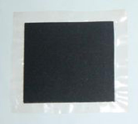
Membrane electrode assembly.
2.3 Fabrication and measurement
The MEA was homemade which used catalyst 30% Pt/C was conditioned at 0.6 V for 1800 s, then 0.4 V for 1800 s and last return to open circuit voltage for 60 s. The MEA conditioning was conducted for five to six times or more until the performances reached a steady state performance (Fang-Bor et al., 2007). After MEA conditioning experiments were started. The heat generated was used to increase the cell temperature. Scribner 850e Fuel Cell Test station issued for conducting the performance of the cell stack. The stack was tested under constant current mode, to generate the polarization and power curves and to stabilize the stack performance as shown in Fig. 2.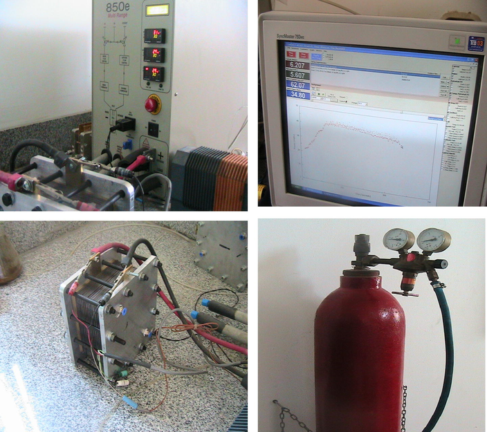
Fuel cell stack test station.
2.4 PEMFC stack prototype
2.4.1 Fuel cell stack design calculations
Design calculations of the fuel cell stack based on desired operating point of cell voltage and cell current density, with a fuel utilization Uf and oxidant utilization, Uox (Fuel Cell Handbook, Seven Edition, 2004) will be as follows:
The total fuel cell current determined by the relation
Because each individual fuel cell will operate at certain current density, we determine the total area required as,
The number of required stacks and cells is calculated simply as
The quantity of hydrogen consumed within the fuel cell is
For the air supply requirement, the stoichiometric ratio of hydrogen to oxygen is 2 to 1 or H2O. The Uf fuel utilization (80%). Thus, the moles of oxygen required for the fuel cell reaction are determined by
Because dry air contains 21% O2 by volume, or by mole percent, the UOx oxidant utilization (80%). The required mass flow rate of dry air is,
2.4.2 Design and manufacture of a 70 W fuel cell stack
A 70 W short stack was designed and manufactured for the following study. The design and specifications of short stack are shown in Table 1. This stack consists of two end plates, 69 bipolar plates, 68 MEAs and gaskets. The end plates were made of Aluminum alloy 6061 and the current collector was made of brass whose role is to conduct the electron. The stack was built from graphite composite bipolar plates (Fang-Bor et al., 2007). Six serpentines type flow fields were used for homogenous gas distribution on anode and cathode sides, as shown in Fig. 1. The flow-field channels dimensions of rib, depth and width are 1 mm, the channels active area is (10.7 × 10.7 cm) 114.5 cm2 and the bipolar plate’s dimension is 140 mm × 140 mm. The flow-field plates, gasket layers, and carbon papers were assembled. The MEAs were assembled between two enclosure plates by eight screw joints with a clamping force about 35 kgf/cm2 (Fang-Bor et al., 2007).
Fuel cell stack power, W
70
Design cell voltage, V
0.65
Design cell current density, mA/cm2
100
Cell width, cm
10.70
Cell length, cm
10.70
Cell active area, cm2
114
Cell current, A
11.4
Cell power, W
7.41
No. of cells
10
Stack voltage, V
6.5
Stack current, A
11.4
Raw materials
Catalyst loading, mg/cm2
0.40
Total catalyst, gm (30% Pt/C)
3.04
Carbon paper, m2
0.6
Nafion solution 5% in alcohol, ml
50
Nafion membrane 212, (15 × 15 cm)
20
Graphite plate, (15 × 15 × 0.4 cm)
11
Aluminum plate, (25 × 25 × 1 cm)
2
Brass plate, (25 × 20 × 0.3 cm)
2
Bolts
12
3 Results & discussions
3.1 Effect of flow pattern on the performance of fuel cell
Figs. 3 and 4 show the two designs: design one for square flow pattern bipolar plate and design two for curvilinear flow pattern bipolar plate. The serpentine flow pattern is better than parallel pattern because it forces flow to be inside the cell longer time than parallel pattern.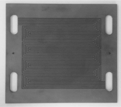
Design one for serpentine flow pattern bipolar plate.
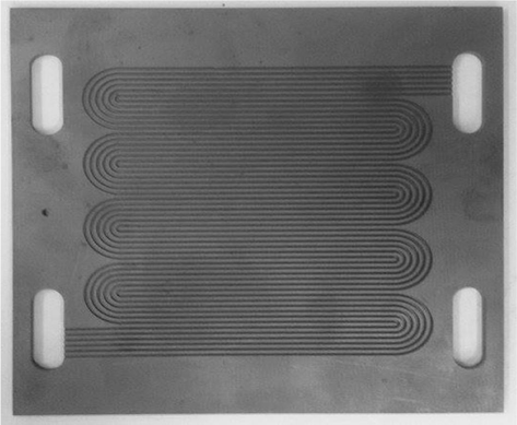
Design two for curvilinear flow pattern bipolar plate.
Fig. 5 demonstrates experimental cell power curves for design one and design two, using air flow rate 42 l/min and hydrogen flow rate 21 l/min as can be seen in the figure that the increase in cell power could have been caused by the differences in the flow velocity inside the channels, the distribution of fuel in the diffusion layer, and for a pressure drop of the fluid inside the channels. As is shown the three different regions are found in PEMFC. Both designs showed that closeness of the output cell power (1 W) up to 15 mA/cm2 cell current density, after reaching 15 mA/cm2 design two shows improvement of cell power than design one.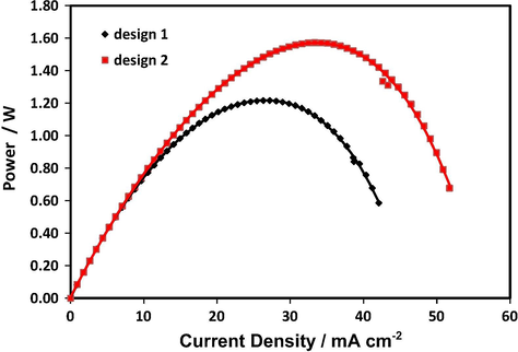
LT-PEMFC power density of the two different designs of bipolar plates at room temperature, operating was using hydrogen flow rate 21 air flow rate 42 l/min. The cathode and anode electrodes were made with 30 wt.% Pt/C E-TEK electrocatalyst, the loading of both was 0.4 mg cm−2. Nafion 212 was used as a membrane.
Based on the results obtained from the single cell studies, the performance evaluation of the two designs of the two flow patterns which show that the flow pattern with curvilinear bends gives better performance than the flow channels with square bends, which are combatable with the results comes out from the modeling and simulation done using COMSOL software (Youssef et al., 2012). This is due to the absence of sharp turns in the curvilinear bends design and consequently the gases flow with no eddies or vortices. The six serpentine flow channels with curvilinear bends have been selected to be the flow pattern for fabrication of the bipolar plate to build the fuel cell stack. The bipolar plate was made of graphite and the flow pattern machined using CNC.
3.2 PEMFC stack performance evaluation
Different stack assembled, 6 cells and 11 cells with electrode active area of 114 cm2 for each cell were assembled in our laboratory with six serpentine flow channels with curvilinear bends for anode and cathode bipolar plate design. Fig. 6 shows the 2 and 11 cells stack assembly. Figs. 7–9 show a typical polarization, power density and power curves obtained from the 2, 6 and 11 cells stack. Data were collected at 5 psi back pressure for H2 and air, room temperature. Fig. 7 shows the polarization curve of the three stacks where the open circuit potential was 1.8, 5.4 and 9.9 V and the limiting current density was 170, 220 and 250 mA cm−2. Fig. 8 shows the power density vs the current density, where the power density increase with the increase in current density reaches the maximum power density 43, 55 and 65 mW/cm2 for the 2, 6 and 11 stacks then the power density decreases with a further increase in the current density. Fig. 9 shows the stack power vs the current density, where the power increase with the increase in current density reaches the maximum power 9.8, 35 and 70 W then the power decreases with a further increase in the current density.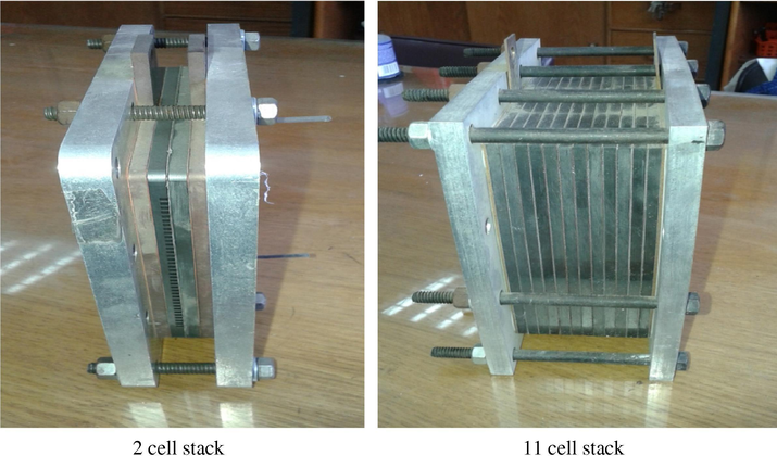
Two, six and eleven cells stack assembly.
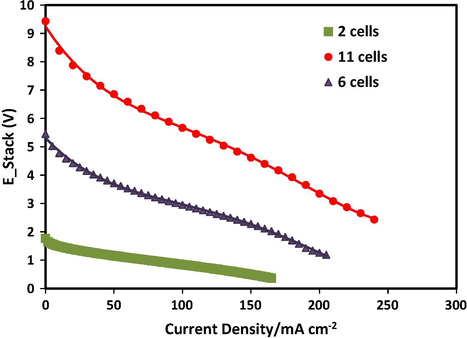
LT-PEMFC polarization curves of different cell stacks at room temperature, operating was with 5 psi H2 and air back pressure. The oxidant was supplied from an air compressor under atmospheric pressure. The cathode and anode electrodes were made with 30 wt.% Pt/C E-TEK electrocatalyst, the loading of both was 0.4 mg cm−2. Nafion 212 was used as a membrane.
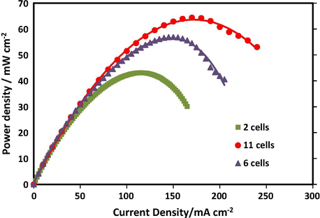
LT-PEMFC power density curves of different cell stacks at room temperature, operating was with 5 psi H2 and air back pressure. The oxidant was supplied from an air compressor under atmospheric pressure. The cathode and anode electrodes were made with 30 wt.% Pt/C E-TEK electro catalyst, the loading of both was 0.4 mg cm−2. Nafion 212 was used as a membrane.

LT-PEMFC power curves of different cell stacks at room temperature, operating was with 5 psi H2 and air back pressure. The oxidant was supplied from an air compressor under atmospheric pressure. The cathode and anode electrodes were made with 30 wt.% Pt/C E-TEK electro catalyst, the loading of both was 0.4 mg cm−2. Nafion 212 was used as a membrane.
4 Conclusion
In this work, a different short PEMFC stack was manufactured and tested. Different bipolar plate flow pattern has been investigated and optimized. The bipolar plates were manufactured using CNC machining. Membrane electrode assemblies (MEAs) were produced by spreading catalyst ink on the gas diffusion layer (GDL). Different fuel cell stack was assembled with 6 and 11 cells each. The test was carried out with H2 at anode and air at cathode side with stoichiometric ratios 1.2 and 2, respectively. The stacks were tested at room temperature. The results showed that the stack has a maximum power of 71 W at 170 mA/cm2 with 11 cells stack.
Acknowledgment
This work was supported by the Egyptian Science and Technology Development Fund (STDF). The project number was “1310” and entitled as “Modeling, Construction and Performance Analysis of Proton Exchange Membrane Fuel Cell (PEMFC) as Clean Portable Power Source”.
References
- Development of a novel portable-size PEMFC short stack with electrodeposited Pt hydrogen diffusion anodes. Int. J. Hydrogen Energy. 2010;35(11):5521-5527.
- [Google Scholar]
- Effect of clamping pressure on the performance of a PEM fuel cell. J. Power Sources. 2007;166(1):149-154.
- [Google Scholar]
- Optimization of polytetrafluoroethylene content in cathode gas diffusion layer by the evaluation of compression effect on the performance of a proton exchange membrane fuel cell. J. Power Sources. 2011;196(8):3773-3780.
- [Google Scholar]
- Portable fuel cells. Fundamentals technologies and applications. In: KaKac S., Pramuanjaroenkij A., Vasilier I., eds. Mini-Micro Fuel Cells. Dordrcht: Springer; 2008. p. :87-101.
- [Google Scholar]
- Theoretical and experimental investigations on thermal management of a PEMFC stack. Int. J. Hydrogen Energy. 2011;36(13):8030-8037.
- [Google Scholar]
- EG&G Technical Services Inc., 2004. Fuel Cell Handbook, seventh ed.
- Characterization of PEMFCs gas diffusion layers properties. J. Power Sources. 2006;156(1):8-13.
- [Google Scholar]
- Design, fabrication and performance analysis of a 200W PEM fuel cell short stack. J. Power Sources. 2007;171:179-185.
- [Google Scholar]
- Influence of the bolt torque on PEFC performance with different gasket materials. Int. J. Hydrogen Energy. 2011;36(20):1343-1350.
- [Google Scholar]
- Effect of gas diffusion layer compression on PEM fuel cell performance. J. Power Sources. 2006;159(2):922-927.
- [Google Scholar]
- Effect of gas diffusion layer compression on the performance in a proton exchange membrane fuel cell. Fuel. 2008;87:2420-2424.
- [Google Scholar]
- Thermal and electrical experimental characterisation of a 1 kW PEM fuel cell stack. Int. J. Hydrogen Energy. 2013;38(13):5348-5356.
- [Google Scholar]
- Performance evaluation of a fuel processing system based on membrane reactors technology integrated with a PEMFC stack. Int. J. Hydrogen Energy. 2011;36(16):9906-9915.
- [Google Scholar]
- Experimental analysis of cathode flow stoichiometry on the electrical performance of a PEMFC stack. Int. J. Hydrogen Energy. 2007;32(6):710-716.
- [Google Scholar]
- Mass, charge and energy transport phenomena in a polymer membrane (PEM) used in a direct methanol fuel cell (DMFC): modelling and experimental validation of fluxes. J. Membr. Sci.. 2006;276:272-285.
- [Google Scholar]
- Experimental evaluation into novel, low cost, modular PEMFC stack. Energy Proc.. 2012;29:567-575.
- [Google Scholar]
- Experimental study of clamping effects on the performances of a single proton exchange membrane fuel cell and a 10-cell stack. J. Power Sources. 2009;192(2):475-485.
- [Google Scholar]
- Operating characteristics of 40W-class PEMFC stacks using reformed gas under low humidifying conditions. J. Power Sources. 2008;178(2):711-715.
- [Google Scholar]
- The influence of stack clamping pressure on the performance of PEM fuel cell stack. Curr. Appl. Phys.. 2010;10(2, Suppl. 1):S59-S61.
- [Google Scholar]
- Youssef, M.E., Galal, Walaa M., Elzatahry, A.A., Sorour, M.M., 2012. Design and modeling of bipolar plates for PEMFC by using comsol software. In: Proceeding of the Global Conference on Global Warming (GCGW-2012) 8–12 July 2012, Istanbul, Turkey, pp. 41–53.


