

Translate this page into:
Effect of sodium dodecyl sulfate surfactant on the surface properties of electroless NiP-TiO2-ZrO2 composite coatings on magnesium AZ91D substrate
⁎Corresponding author. prabakaran@yu.ac.kr (Rajendran Prabakaran) praba.auto@gmail.com (Rajendran Prabakaran)
-
Received: ,
Accepted: ,
This article was originally published by Elsevier and was migrated to Scientific Scholar after the change of Publisher.
Abstract
This research incorporated nano TiO2 and ZrO2 particles into the NiP electroless bath to produce NiP-TiO2-ZrO2 composite deposits on magnesium AZ91D substrates. The impact of sodium dodecyl sulfate (SDS) (anionic surfactant) was utilized for deposition to minimize the agglomeration and clustering of particles in the electroless bath. Surface properties such as atomic force microscopy, energy dispersive X-Ray analysis, scanning electron microscopy, and X-ray diffraction are used to evaluate the surface morphologies of coating, surface roughness, elementary composition, and crystalline structure of the deposits. Furthermore, the impact of SDS surfactant on the corrosion properties of deposits was also studied using potentiodynamic polarization in a 5 wt% NaCl solution. The overall results reveal that incorporating anionic surfactant SDS at the optimum concentration of 1.5 g/L (CMC value) improved wettability, deposition rate, and surface roughness compared to the deposits developed without surfactant. The proposed mechanism is that the molecules of SDS surfactant could come into contact with the surface of NiP-TiO2-ZrO2 composite coating in the bath, increasing nanoparticle dispersion and resulting in a uniform coating. Furthermore, the electrochemical results show improved corrosion protection efficiency (PE%) of NiP-TiO2-ZrO2 composite coatings by increasing the concentration of SDS surfactant, achieving ∼87.9% at (1.5 g/L) CMC value.
Keywords
AZ91D alloy
Electroless coating
Sodium Dodecyl Sulfate
Surface roughness
Contact angle
Corrosion resistance

1 Introduction
Magnesium alloys offer a variety of superior characteristics, including high thermal conductivity, low density, strong electromagnetic shielding properties, high strength-to-weight ratio, and excellent machinability (Alirezaei et al., 2007; Huang and Yang, 2020). They are commonly utilized in aerospace, automotive, military assembly, sports, microelectronics, and other industries (Alirezaei et al., 2013). However, magnesium alloys are limited to their large-scale usage in industries because of their poor surface roughness, high chemical reactivity, poor creep resistance, and poor wear and corrosion resistance (Chintada and Koona, 2018). To provide protective surface treatment for the future application of magnesium alloys, which may prevent the substrate surface's excellent behavior while protecting them from corrosion and wear (Zielińska et al., 2012). Surface coating technique that partly or entirely covers a surface of the material to improve electrical, mechanical, and magnetic behaviour. Several surface coatings technologies have improved surface characteristics, such as thermal spraying, electroplating, electroless, physical vapor deposition (PVD), and chemical vapor deposition (CVD). However, these technologies have limitations, such as uneven coating and expensive costs (Farzaneh et al., 2010). The electroless coating method is relatively beneficial over all other technologies due to the low-cost homogenous deposition on complicated geometries and the simple procedure scientists recognize for preparing nanocomposite coating on magnesium alloys. Compared to traditional electroplating, it has proven an alternative and attractive approach for creating thin and homogenous deposits on the magnesium substrate surface (Chen et al., 2017).
The electroless nickel-phosphorus (E-Ni-P) deposits are extensively used in a wide range of applications because they suit a broad range of requirements, such as aerospace, petroleum, electronics, chemical, textiles, machinery, and automobile industries (Sharma and Singh, 2013; Fayyad et al., 2021). Recently, nanocomposite coatings are gaining popularity because Ni-P coatings mixed with second-phase nanoparticles increase the apparent characteristics. The essential behaviour, such as excellent corrosion and wear properties, may be further improved by including different nanoparticles in the Ni matrix, resulting in NiP composite deposits (Islam et al., 2015a,b). The behaviour of composite deposits is determined by numerous factors, such as the coating structure, the bath composition, and the shape, type, and size of the embedded nanoparticles (Lee, 2012). Incorporating nano-size particles into NiP coatings significantly increases their characteristics and performance, prompting attention to metal matrix nanocomposite coatings (Liu et al., 2019). The most frequently used second-phase hard nanoparticles include Silicon dioxide (SiO2), Silicon carbide (SiC), Zirconium oxide (ZrO2), Titanium dioxide (TiO2), Aluminium oxide (Al2O3), Cyanide nitrogen (C3N4), Tungsten carbide (WC), Diamond (C), Boron carbide (B4C) Carbon nanotubes (CNTs) and Titanium carbide (TiC) nanoparticles co-deposited with electroless NiP coatings (Elansezhian et al., 2009). Several factors determine the inclusion and dispersion of second-phase nanoparticles throughout the NiP matrix, including pH, agitation speed, particle concentration in the electroless plating bath, reducing agent, the concentration of Ni ions, and the existence of a surfactant (Fayyad et al., 2019a,b). The amount of reinforced particles in the coating is determined mainly by the size of the secondary particles in the electroless plating bath. The particle deposition rate in the prepared electroless coating accelerates until the particle concentration is optimum (Fayyad et al., 2019a,b). The possibility of secondary particles depositing on the coating decreases when particle accumulation in the electroless coating solution reaches a specified level (Chintada et al., 2021a). For instance, with particle concentrations of up to 70 g/L in the deposition solution, the deposition rate of Al2O3 particles into the electroless coating increases (Gawad et al., 2013). The greater amount of SiC nanoparticles can uniformly spread inside the coating matrix owing to the particle concentration of 2 g/L respectively (Farzaneh et al., 2013). NiP composite coatings made with the right proportions of S3N4 and SiO2 particles provide adequate corrosion protection (Islam et al., 2015a,b). Incorporating ZrO2 and TiO2 nanoparticles into the deposits has encouraged enormous attention in the scientific community due to its many applications in engineering components. According to the studies, adding ZrO2 and TiO2 nanoparticles improved corrosion resistance and other behaviour, such as photocatalysis and electrocatalysis (Sudagar et al., 2013). The main advantages of composite deposits were evaluated by the optimum concentration and stable dispersion of nanoparticles in the electroless bath (Ranganatha et al., 2010).
Moreover, the homogenous dispersion of nanoparticles would be restricted owing to the agglomeration and segregation of nanoparticles with greater active and surface energy in the electroless bath. Uniform coatings containing well-scattered nanoparticles are essential for increased corrosion resistance (Shu et al., 2015). Magnetic stirring and ultrasonication are often used to keep the nanopowder in the solution. The surfactants are widely used in electroless baths for nanoparticle separation (Ansari and Thakur, 2017).
Surfactants are carefully introduced to the electroless bath at the appropriate proportions. Surfactant binds with the Ni and significantly lowers the generation of H2 (Hydrogen) gas bubbles during the deposition reaction stage. It results in minimal porosity homogenous deposits and increases the coatings deposition rate in magnesium substrate (Chen et al., 2010). The critical micelle concentration (CMC) describes surfactants and their capacity to provide a stable deposit with appropriate characteristics (Zhang et al., 2010). It is the concentration at which a pronounced break or sudden change in the surface tension curve can be seen. It coincides with the onset of micelle formation and a sharp drop in surface tension. This point's concentration is regarded as the CMC. A contact angle meter can be used to determine the surfactant's CMC value. For the specific solution, the lowest angle is reached at the CMC value. Surfactants may also increase the suspended nanoparticle's electrostatic adsorption and surface charge, increasing the number of nanoparticles in the deposit (Yang et al., 2011; Saoudi et al., 2020; Blkoor et al., 2022). Even though the cationic surfactant enhances the proportion of C3N4 inclusion in the coating, the polymeric surfactant results in a composite coating with maximum microhardness (Fayyad et al., 2019a,b). The inclusion of non-ionic or ionic surfactants in an electroless bath solution improves the wettability of the ENiP nanocomposite coating surface (Fayyad et al., 2018a,b). The addition of sodium dodecyl sulfate (SDS) with nanoparticles transformed the morphology of the electroless deposit from a nodular to a smooth surface as the SDS surfactant lowered the contact angle and increased the wettability of the NiP deposit on the substrate surface (Fayyad et al., 2018a,b). Meanwhile, it is still challenging to choose the right surfactant for each deposition due to the complicated chemical reaction mechanism and particular electroless technique dependent on the composition of the bath (Yu et al., 2011). The anionic surfactant sSDS has effectively stabilized and dispersed the ZrO2 and TiO2 nanoparticles in the NiP coatings, demonstrating that greater nanoparticles deposited in the magnesium substrate at optimum concentration and enhanced the corrosion resistance (Momenzadeh and Sanjabi, 2012). However, few studies have attempted to investigate the dispersion stability of TiO2 and ZrO2 nanoparticles in the baths. There has been no study on the interaction of ZrO2 and TiO2 nanoparticles with SDS anionic surfactant during composite coating production.
It is the first attempt to deposit the ZrO2 and TiO2 nanoparticles within the NiP matrix using the electroless coating technique on magnesium AZ91D alloy. However, the main focus has been given to the effect of SDS surfactants on the stability of nano ZrO2 and TiO2 dispersions in the electroless bath solution at the temperature of 90 ± 2 °C. The bath with the (1.5 g/L) optimal concentrations of ZrO2 and TiO2 nanoparticles was selected as the usual model for the surfactant analysis. The research mainly focused on the impact of NiP-TiO2-ZrO2 on deposition rate, surface morphology, and elementary composition. Additionally, the impact of SDS surfactant on the deposition rate, surface roughness, corrosion, and contact angle behaviour of NiP-TiO2-ZrO2 coatings are examined.
2 Experimental details and procedure
2.1 Materials
This study chose a lightweight and excellent machinability character magnesium AZ91 alloy (Huang and Yang 2020) substrates cut into 20 mm × 15 mm × 3 mm dimensions as substrate material for depositing ENiP-TiO2-ZrO2 composite deposits. Table 1 shows the elemental composition of the magnesium AZ91D alloy samples. Fig. 1 depicts the X-ray diffraction (XRD) pattern of the base magnesium AZ91D alloy containing significant peaks of β-Mg17Al12 and α-Mg. TiO2 and ZrO2 nanoparticles (99.7% purity), with a particle size of (<80 nm) purchased from Sigma Aldrich, were chosen as second-phase nanoparticles in the bath solution.
Elements
Mg
Al
Zn
Mn
Wt%
89.42
9.4
0.86
0.32
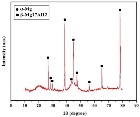
XRD diffraction pattern of magnesium AZ91D alloy.
The SEM micrograph in Fig. 2(a) reveals that the ZrO2 nanoparticle is structured and appears light grey at high magnification. While the XRD pattern in Fig. 2(b) shows the existence of significant peaks of zirconium oxide. The SEM image in Fig. 2(c) reveals that the TiO2 nanoparticle is regularly shaped and appears grey at high magnification. While the XRD image in Fig. 2(d) shows the presence of significant peaks of titanium dioxide, respectively.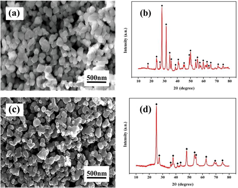
Surface morphology and elemental composition (a) ZrO2 nanoparticle and (b) TiO2 nanoparticle.
SDS is an anionic surfactant procured from Sigma Aldrich. The surfactant concentration was taken above and below its CMC value. From the earlier research, the CMC value for SDS is found to be 1.2 g/L. Thus the concentration was chosen as 0.5 g/L, 1.0 g/L, 1.5 g/L, 2.0 g/L of surfactant. The zeta potential of ENiP-TiO2-ZrO2 nanoparticles is measured using the Zetasizer Nano ZS90 (Malvern Instruments Ltd, UK) both with and without surfactants. Fig. 3(a) indicates that the zeta potential value of −30.5 mV for nanoparticles with surfactants (-19.2 mV for without surfactant). The Fig. 3(b) also indicate that the mean diameter of the particle size distribution was smaller for the nanoparticle with SDS (586 d.nm) compared to the nanoparticle without surfactants (961 d.nm). Since the stability of colloidal solutions is influenced by electro-kinetic properties, the kind of surfactants plays a crucial role (Sundaram et al., 2023). This confirms that the nanoparticle prepared with surfactants exhibit stable deposits and have desirable characteristics.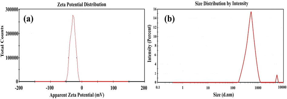
Zeta potential reports of the NiP-TiO2-ZrO2 with SDS (1.5 g/L): (a) charge distribution and (b) particle size distribution.
2.2 Deposition method
Before electroless plating, all the substrate of magnesium AZ91D alloy was disc polished and manually polished with different grades of fine sandpaper of 800, 1000, and 1200 mesh grit size. The surface roughness of the magnesium substrate was analyzed using a stylus instrument with a mean surface roughness of 0.60 µm. The magnesium substrate was ultrasonically cleaned in acetone for 20 min before being rinsed with deionized water, degreased by the ethanol for 15 min, and then, all the specimens were activated by dipping in 50% volume of H2SO4 (Sulfuric acid), and HCl (Hydrochloric acid) solution for 40 sec at ambient temperature. Finally, before being moved to the electroless bath, the samples were washed with distilled water.
The experimental setup of the electroless deposit is shown in Fig. 4. In the deposition method, nickel sulfate (NiSO4) is used as the nickel source, ammonium chloride (NH4Cl) acts as the complexing agent, and sodium hypophosphite (NaPO2H2) serves as a reducing agent in the electroless plating bath. Meanwhile, tri-sodium citrate was used to stabilize the electroless bath from decomposition. The operation condition parameter and bath composition for electroless nanocomposite coatings with SDS surfactants are shown in Table 2. The electroless bath's pH was determined using an Eco tester pH meter and kept at 5 ± 0.02 throughout the plating process by utilizing a 25% volume of aqueous ammonia solution (NH3) as a pH controller. A previous study found that the pH of the coatings affects the phosphorus (P) level. The thickness of the coating also varies with pH, with neutral or acidic baths providing thicker coatings than alkaline baths. Similarly, the coating thickness and phosphorus level had an inverse relationship. The pH 5 value is selected to attain an optimum phosphorus level and the appropriate coating thickness range for the Ni-P coatings (Czagany and Baumli, 2017).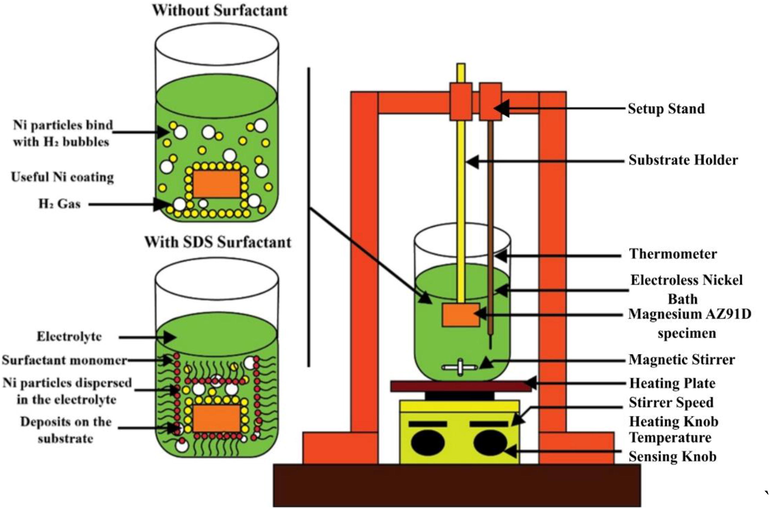
The experimental setup of the electroless deposit.
Constituent
Function
Quantity (g/L)
Nickel Sulfate
Source of Nickel
25
Sodium Hypophosphite
Reducing Agent
15
Tri-Sodium Citrate
Stabilizer
36
Ammonium Chloride
Complexing Agent
50
Nano TiO2-ZrO2
Co-Deposits
(1.5–1.5)
SDS Surfactant
Dispersant
0.5, 1.0,
1.5 and 2.0
Critical micelle concentration (CMC)
_
2.395
The experiment of the bath solution was conducted at a temperature and magnetic stirring rate of 90 ± 2 °C and 400 rpm, respectively. The concentration level of TiO2 and ZrO2 nanoparticles in the bath was fixed at 1.5g/L. The quantity of distributed TiO2 and ZrO2 nanoparticles in the bath significantly influenced the level of incorporation in the deposit. However, a high proportion of TiO2 and ZrO2 nanoparticles (2.0 g/L) causes particle agglomeration (Fayyad et al., 2019a,b). In previous literature (Ansari and Thakur, 2017), it was observed that concentration levels greater than 1.5g/L seem to be saturated when the concentration level is increased up to 10g/L level.
The varying SDS surfactant concentration from 0.5 to 2.0 g/L was calculated using SDS surfactant CMC values as described in Table 2. Before the coating operation, the desired quantity of ZrO2 and TiO2 nanopowder was weighted and ultrasonically dispersed in 20 mL of distilled water with an adequate amount of SDS surfactant for 25 min. After depositing the NiP coating for 20 min, the prepared nanopowder suspension was introduced into the electroless bath solution within 1 min at a uniform rate, and the deposition proceeded for 40 min. The mechanical stirring at a constant speed of 400 rpm was utilized, and the overall deposit duration was 60 min. For comparison, the above procedure was used to deposit a NiP-TiO2-ZrO2 composite coating with and without SDS surfactants. After electroless plating, the NiP-TiO2-ZrO2 deposited was cleaned with distilled water and allowed to dry in the air at ambient temperature.
2.3 Electroless Ni-P layer formation mechanism
The mechanism identified in the bath solution is the instantaneous adsorption of the H+ and Ni2+ on active sites of the substrate surface. The reduction of P+1 and Ni+2 in the existence of NaPO2H2 as a reducing agent causes the development of NiP deposits on the required substrate surface, as shown in Fig. 5. The surface behaves as both a catalyst and substrate during the rapid deposition (Amini and Sarabi, 2011). During the reaction, the H + concentration rises; hence pH is controlled throughout the reaction is necessary. Based on the mechanism formation of the NiP layer in the magnesium substrate (Taşci et al., 2019).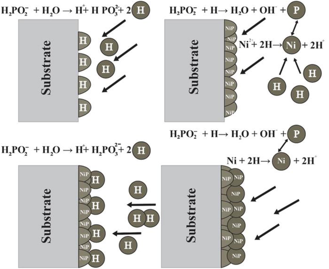
Mechanism of Ni-P layer formation on a magnesium substrate.
2.4 Coating characterization
The surface micrograph of the electroless NiP-TiO2-ZrO2 deposits using various surfactant concentrations composite was evaluated through a scanning electron microscope (SEM) using the model (FEI Quanta, FEG 200) attached with Energy Dispersive X-ray Analysis (EDAX). The X-Ray Diffraction (XRD) analysis was utilized to identify the elementary composition of the deposits. The crystalline structure of the NiP-TiO2-ZrO2 deposits was studied by X-Ray diffraction technique using the model (Xpert Shimadzu) at 40 kV with Cu Kα radiation (λ = 1.54065 Å) by scanning range from 2θ = 20 to 70°.
The rate of deposition of the ENiP-TiO2-ZrO2 is indicated by weight gained throughout the deposition stage. The as-deposited surface was dried periodically and weighed until no more variation in the reading was recorded. On the other hand, the deposition rate (D) was calculated by dividing the deposit thickness by the entire deposition duration (T). The rate of deposition may be represented using the below equation,
An atomic force microscope (AFM) calculates the mean roughness deviation. The mean roughness (Ra) was measured utilizing AFM (Asylum Research) on a nanoscale, with the silicon probe using the model (Veeco model-OLTESPA, Olympus) with the resonance of 70 kHz and a spring constant of 2 N/m, respectively. The contact angle [Model: 200-k1 goniometer (Rame-hart Instrument, USA)] was measured on the deposited surface using the sessile drop (DI water) technique. The corrosion behaviour was evaluated using potentiodynamic polarization corrosion test equipment CHI 1240B (CH Instruments, USA) under the ASTM G 59-97 standard.
The corrosion resistance experiment for ENiP-TiO2-ZrO2 deposits in 5 wt% NaCl solution was carried out at a temperature of around 25 °C. The electrochemical test setup includes saturated silver/silver chloride (Ag/AgCl) as a reference electrode, graphite wire as a counter electrode, and as-deposit composite coatings as working electrodes. The experiment was performed at a +0.2 to −0.2 V scanning rate against open circuit potential (OCP). Before each experiment, a 15 min setting period was set to stabilize the OCP. The current density (Icorr) and potential (Ecorr) were calculated using a Tafel plot. Thus, the corrosion rate (mpy) may be calculated using the below equation,
3 Results and discussion
3.1 Surface morphology of ENiP-TiO2-ZrO2 deposits without and with SDS surfactant
Fig. 6 represents the FESEM micrographs of ENiP-TiO2-ZrO2 deposits with and without SDS surfactant. Fig. 6(a) FESEM micrographs show the nodular appearance and the existence of microvoids and agglomeration of nano TiO2 and ZrO2 particles developed at 10–40 µm in the absence of SDS surfactant addition.![Surface morphology of the NiP-TiO2-ZrO2 deposits: (a) Without surfactant, With SDS. anionic surfactant [(b) 0.5 g/L, (c) 1.0 g/L, (d) 1.5 g/L, (e) 2.0 g/L].](/content/184/2023/16/9/img/10.1016_j.arabjc.2023.105028-fig6.png)
Surface morphology of the NiP-TiO2-ZrO2 deposits: (a) Without surfactant, With SDS. anionic surfactant [(b) 0.5 g/L, (c) 1.0 g/L, (d) 1.5 g/L, (e) 2.0 g/L].
Furthermore, the surface of the deposits contains a considerably reduced quantity of Ni on the magnesium substrate surface, resulting in increased surface roughness due to the non-uniform deposition. When the SDS surfactant was added to the electroless bath, the surface morphology appearance dramatically transformed from an irregular nodular structure to a uniform, smooth, fine, and compact surface of about 5 µm, decreasing the surface roughness values. The optimum concentration of SDS surfactant in ENiP-TiO2-ZrO2 deposits enhances the nucleation sites and inhibits particle growth. It results in a significant rise in the deposition rate on the magnesium substrate in the existence of SDS surfactant (Nwosu et al., 2012). Fig. 6(b)–(d) reveals that increasing the concentration of SDS surfactant from 0.5 g/L to 1.5 g/L results in homogenous deposition of nanoparticles with a smooth surface is obtained. However, the particle size increases when the SDS surfactant concentration increases by 2.0 g/L of CMC value (Alsari et al., 2001). The reason is increasing the SDS surfactant concentration level beyond a certain point, the nanoparticle in the bath solution tends to agglomerate, resulting in uneven dispersion of nanoparticles, few micro-voids, and coarse particles, as appeared in Fig. 6(e) SEM micrograph.
Fig. 7(a)–(c) depicted the elementary composition of the ENiP-TiO2-ZrO2 deposits with and without SDS surfactant concentration of (1.5 g/L) CMC value deposits determined by EDAX analysis, which proves the existence of Zr, Ti, Ni, O, and P elements in the deposits and scanning the chosen region to determine the percentage of each element. Table 3 shows that the addition of SDS surfactant reduced the nickel level rwhile the phosphorus level of the deposits increased from 4.80% to 5.64% respectively.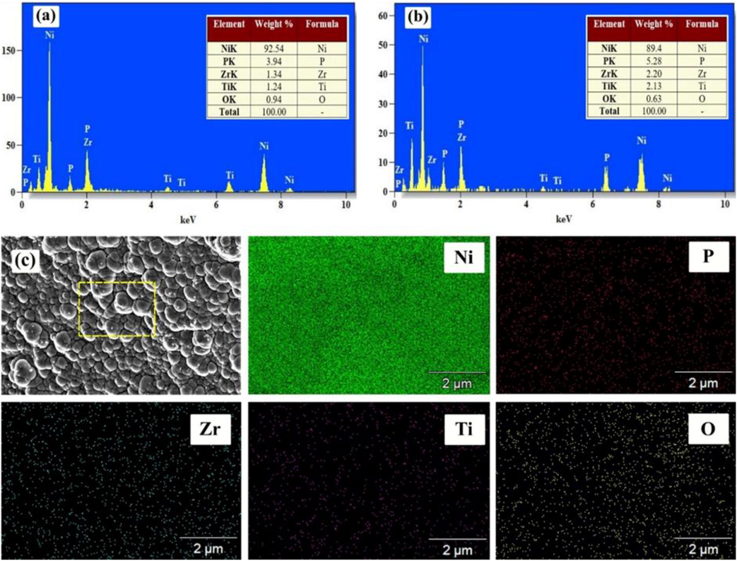
EDAX mapping analysis of the NiP-TiO2-ZrO2 deposits: (a) Without surfactant, (b) With SDS surfactant 1.5 g/L of CMC value.
Elements (wt%)
SDS concentration
Without Surfactant
(0.5 g/L)
(1.0 g/L)
(1.5 g/L)
(2.0 g/L)
Ni
92.54 ± 1.4
90.8 ± 1.4
90.1 ± 0.7
89.4 ± 0.8
92.08 ± 0.2
P
3.94 ± 0.2
4.80 ± 0.1
5.28 ± 0.2
5.64 ± 0.3
5.18 ± 0.1
Zr
1.34 ± 0.4
1.82 ± 0.3
1.97 ± 0.4
2.20 ± 0.1
1.14 ± 0.2
Ti
1.24 ± 0.1
1.76 ± 0.2
1.89 ± 0.1
2.13 ± 0.3
1.06 ± 0.2
O
0.94 ± 0.3
0.82 ± 0.2
0.76 ± 0.3
0.63 ± 0.1
0.54 ± 0.1
Fig. 8 shows the X-ray diffraction of ENiP-TiO2-ZrO2 deposits developed without and with the SDS surfactant addition. The inclusion of SDS surfactant results in a combination of amorphous phases and non-crystalline structure observed in the ENiP-TiO2-ZrO2 deposits. The change in the crystalline structure occurs during the production of ENiP-TiO2-ZrO2 deposits by increasing the concentration of SDS surfactant. One prominent peak at 2θ = 44.60° is observed in all the X-ray diffraction patterns. Similarly, one large and two minor peaks of lesser intensity were observed for ENiP-TiO2-ZrO2 deposits at Ni (1 1 1), ZrO2 (1 1 1), and TiO2 (2 2 0).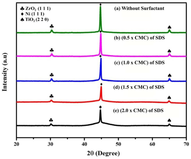
XRD diffraction pattern of the NiP-TiO2-ZrO2 deposits.
Table 4 depicts the change in XRD parameters of the ENiP-TiO2-ZrO2 deposits without and with the surfactant addition on the magnesium substrate. The Debye-Scherer equation may be used to calculate the crystallite grain size (d) of nickel by using the below equation,
Parameters
Without SDS. Surfactant
With SDS. surfactant
0.5 g/L
1.0 g/L
1.5 g/L
2.0 g/L
The peak position of Niin
(°)44.56°
44.61°
44.59°
44.53°
44.55°
FWHM
0.250
0.390
0.420
0.545
0.540
Crystalline Size (nm)
39.501
25.295
23.504
18.126
18.302
3.2 Deposition rate of ENiP-TiO2-ZrO2 deposits without and with SDS surfactant
Fig. 9 depicts the influence of SDS surfactant addition on the deposition rate of ENiP-TiO2-ZrO2 composite coatings on the magnesium alloy. The graph indicates that the variation in the SDS surfactant concentration significantly impacts the deposition rate. The rate of deposition of 1.5 g/L of ENiP-TiO2-ZrO2 composite sample without SDS surfactant was observed to be 15 µm/hr. The deposition rate increases as the SDS surfactant concentration increases from 0.5 g/L to 1.5 g/L of CMC value, reaching a maximum value of 34 µm/hr. A condition known as CMC was developed by varying the surfactant concentration to obtain the highest deposition rate. The CMC value about 1.5 g/L of SDS surfactant has a maximal deposition rate compared to without surfactant. The time duration of deposition was similar across all the coatings, regardless of the variation in SDS surfactant concentration.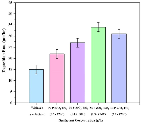
Deposition rate of the NiP-TiO2-ZrO2 deposits with different SDS surfactant concentrations.
The coating thickness measurement refers to the distance between the outermost surface of the coating and the original substrate surface. The thickness of the coating (CT) was determined by SEM using the model (Supra 55, Carl Zeiss Germany) across the cross-section of the deposited specimen that has undergone diamond polishing. The thickness of the coating is measured in three separate areas. Deposit thickness, on the other hand, refers to the measurement of material accumulation that occurs naturally or unintentionally on a surface. The coating thickness values are reported in Table 5, and the deposit thickness (DT) is calculated using the below equation for varied surfactant concentrations.
Different surfactant concentration
Without SDS. surfactant
With SDS Surfactant (g/L)
–
0.5
1.0
1.5
2.0
Deposit thickness (μm)
8.50 ± 0.5
15.40 ± 0.61
16.15 ± 0.51
18.54 ± 0.68
16.70 ± 0.58
Coating thickness (μm)
7.986 ± 0.58
14.476 ± 0.60
15.686 ± 0.53
17.760 ± 0.60
16.458 ± 0.56
The deposition rate rises as the concentration of SDS surfactant in the electroless bath increases. It is due to the nickel (Ni) particle monolayer development on the magnesium substrate surface. It happens when the anionic monomer negative head group points towards the magnesium substrate surface, which makes the deposition simple (Afroukhteh et al., 2012). However, increasing the concentration of SDS surfactant to 2.0 g/L of CMC value reduces the deposition rate due to the surfactant saturation over the CMC value conditions. It may be due to excess SDS surfactant in the electroless bath (Tamilarasan et al., 2015). The deposition rate is subsequently affected because the SDS surfactant particles seem more liable to surround the cathode surface and restrict the Ni2+ ion diffusion across the substrate surface (Nwosu et al., 2012).
SEM images of the ENiP-TiO2-ZrO2 composite deposits with and without SDS surfactant, are depicted in Fig. 10. It is clearly reveals the interface, coating layer, and magnesium substrate. Fig. 10(a) micrograph depicted the cross-section of the deposit without SDS surfactant addition seems to be the low amount of Ni obtained in the magnesium substrate surface with a coating thickness of 7.986 µm. It is because, during the reduction process, a few Ni will float on the top surface and generate H2 gas bubbles. Fig. 10(b)–(d) micrograph shows the cross-section of the deposit with SDS surfactant addition from 0.5 g/L to 1.5 g/L seems to be a considerable rise in the amount of Ni obtained in the magnesium substrate with the highest coating thickness of 17.76 µm. Fig. 10(e) micrograph shows that 2.0 g/L of CMC value of SDS surfactant reduces the coating thickness of 16.458 µm. The cross-section micrographs above show that the decrease in coating thickness was caused without and with SDS surfactant addition over a certain limit, respectively.![Cross-sectional morphology of the NiP-TiO2-ZrO2 deposits: (a) Without surfactant, With SDS. anionic surfactant [(b) 0.5 g/L, (c) 1.0 g/L, (d) 1.5 g/L, (e) 2.0 g/L].](/content/184/2023/16/9/img/10.1016_j.arabjc.2023.105028-fig10.png)
Cross-sectional morphology of the NiP-TiO2-ZrO2 deposits: (a) Without surfactant, With SDS. anionic surfactant [(b) 0.5 g/L, (c) 1.0 g/L, (d) 1.5 g/L, (e) 2.0 g/L].
3.3 Surface roughness of ENiP-TiO2-ZrO2 deposits without and with SDS surfactant
The differences in the mean roughness value of the ENiP-TiO2-ZrO2 composite deposits with and without the inclusion of varying SDS surfactant concentrations were studied using AFM, and the findings are represented in Fig. 11(a)–(e). In absence of surfactant, the result shows an increased coarseness, while the existence of SDS surfactant improves the smoothness in deposits surface. The ENiP-TiO2-ZrO2 deposits developed without using SDS surfactant, having a surface roughness with greater (Ra) values of 14.432 nm. When the SDS surfactant is added, the average roughness value of ENiP-TiO2-ZrO2 deposits (Ra) is 6.705 nm, which is considerably lower than the value obtained from the deposit surface in the absence of surfactant.![AFM morphology of the NiP-TiO2-ZrO2 deposits: (a) Without surfactant, With SDS. anionic surfactant [(b) 0.5 g/L, (c) 1.0 g/L, (d) 1.5 g/L, (e) 2.0 g/L].](/content/184/2023/16/9/img/10.1016_j.arabjc.2023.105028-fig11.png)
AFM morphology of the NiP-TiO2-ZrO2 deposits: (a) Without surfactant, With SDS. anionic surfactant [(b) 0.5 g/L, (c) 1.0 g/L, (d) 1.5 g/L, (e) 2.0 g/L].
At the low SDS surfactant concentration, the chemical reaction occurs throughout the electroless bath solution instead of a regulated autocatalytic reaction on the magnesium substrate surface (Afroukhteh et al., 2012). The electroless bath gets unsteady after a one-hour duration. When the chemical reaction is finished, a significant amount of the tiny Ni don’t contribute to the formation of adhering deposits and it settles at the base of the beaker (Song et al., 2007). The tiny Ni particles adhere to the H2 gas produced by the chemical reactions, which causes them to drop and settle at the base of the beaker or disperse in the solution and travel to regions apart from the magnesium substrate surface. Only a tiny proportion of free Ni are deposited under these situations. It justifies the improvement in the Ra of the nickel deposits (Liu et al., 2009). In a similar situation, the concentration of SDS surfactant raises the deposition rate of Ni on the ENiP-TiO2-ZrO2 deposits.
3.4 Contact angle of ENiP-TiO2-ZrO2 deposits without and with SDS surfactant
Contact angle (CA) measurements are used on ENiP-TiO2-ZrO2 deposits with and without the inclusion of varying SDS surfactant concentrations to determine the wettability of the deposit surface. The wettability of the deposit was taken into consideration by the contact angle between the surface and the water. Fig. 12 shows the CA results and water drop images for various deposits. In our study, an SDS surfactant concentration of 1.5 g/L of CMC value resulted in a decreased surface roughness with greater wettability. When the SDS surfactant concentration is increased to 1.5 g/L value, the decrease in the CA value of 79.83° (hydrophilic) was observed. The CA value was determined to be 110.76° (hydrophobic) without surfactant. The inclusion of SDS surfactant in the electroless bath solution caused the CA value to decrease until it reached the optimum CMC requirement, after which the CA value decreased (Elansezhian et al., 2008). It might be attributed to the decrease in roughness attained on the ENiP-TiO2-ZrO2 composite deposits after reaching the CMC requirement. Therefore, the SDS surfactant at 1.5 g/L concentration leads to better wettability. Based on the wettability tests, it is possible to conclude that the surfaces essential for the Ni-P-ZrO2-TiO2 deposition are adequately wetted while SDS surfactants are used. As a result, it is expected that the continuous coating with embedded ZrO2 and TiO2 nanoparticles and strong adhesion to the magnesium AZ91D substrate surface.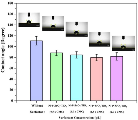
CA of the NiP-TiO2-ZrO2 deposits with and without SDS surfactant.
3.5 Corrosion behaviour of ENiP-TiO2-ZrO2 deposits without and with SDS surfactant
Chemical potentiodynamic polarization curves are used to evaluate the corrosion behaviour of deposits. Fig. 13 shows the Tafel polarization plots for the NiP-TiO2-ZrO2 deposits from the electroless bath with and without the inclusion of various SDS surfactant concentrations after 24-hour immersion in a 5 wt% NaCl solution at room temperature. This figure shows that the polarization curves of the ENiP-TiO2-ZrO2 composite deposits with increasing concentrations of SDS surfactant seem to migrate to the right side. The electroless parameter acquired from the potentiodynamic polarization curves is represented in Table 6, where Y-axis, denotes the current density (Icorr in µA cm−2), and X-axis denotes the corrosion potential (Ecorr in V). Furthermore, corrosion protection (PE) efficiency was estimated using the following formula.
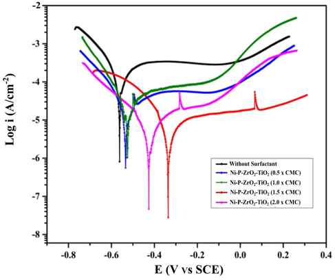
Potentiodynamic polarization curves of the NiP-TiO2-ZrO2 deposits.
Sample
Ecorr (mV)
Icorr (µA/cm−2)
PE (%)
Corrosion rate (mm/yr)
NiP-TiO2-ZrO2 (Without surfactant)
−562.0
65.73
–
1.28
NiP-TiO2-ZrO2 (0.5 × CMC) SDS
−534.0
55.88
14.98%
1.02
NiP-TiO2-ZrO2 (1.0 × CMC) SDS
−526.0
47.93
27.08%
0.87
NiP-TiO2-ZrO2 (1.5 × CMC) SDS
−335.0
8.48
87.39%
0.27
Ni-P-TiO2-ZrO2 (2.0 × CMC) SDS
−426.0
10.24
84.42%
0.29
ENiP-TiO2-ZrO2 deposits without surfactant are observed to have a greater current density of Icorr (65.73 µA cm−2) with an Ecorr of −562.0 mV, while the SDS surfactant concentration increased the corrosion resistance at 1.5 g/L of CMC value. The current density and the corrosion potential for ENiP-TiO2-ZrO2 deposits with SDS surfactant at 1.5 g/L of CMC value were measured as Icorr (8.48 µA cm−2) at a potential of −335.0 mV indicating an 87.39% improvement in corrosion resistance. The 1.5 g/L of CMC value shows that the inclusion of SDS surfactant in the electroless bath solution considerably impacts corrosion properties. For (2.0 × CMC), current density and the corrosion potential were measured as Icorr about 10.24 µA cm−2 at a potential of −426.0 mV, indicating a 3.51% decrease in corrosion resistance compared to 1.5 g/L of CMC value. Electroless ENiP-TiO2-ZrO2 deposits with SDS surfactant show better corrosion resistance compared to those without surfactant addition. The SDS surfactant improves the moist adhesion properties between the deposits and the magnesium substrate surface (Elansezhian et al., 2008). The ability of the SDS surfactant acts as a corrosion barrier by the following factor called CMC, which provides the variable results of different concentrations of SDS surfactant (Aal et al., 2008). The CMC value mentioned above, corrosion rate, and surface tension are unaffected due to the creation of a shielding layer on the substrate surface caused by the deposit of multiple monolayers (Novakovic et al., 2006). The increased phosphorus level of the ENiP-TiO2-ZrO2 deposits may provide a higher resistance to Cl2 attacks on the deposits. As previously stated, the concentration level of SDS surfactant in the electroless bath increases the amorphous proportion of the deposits (Chintada et al., 2021a).
4 Conclusion
In this study, ENiP-TiO2-ZrO2 deposits were developed using the electroless coating technique, and the impact of SDS surfactant on the surface behaviour of the deposits was examined. The test results revealed that varying the SDS surfactant concentration significantly influenced the process. Based on the experimental study, the following conclusion were obtained.
-
The inclusion of SDS surfactant results in the homogenous deposition of Ni produced during the chemical reaction on the magnesium substrate surface.
-
The surface morphology demonstrates that by increasing the SDS surfactant concentration in the electroless bath to 1.5 g/L (CMC value), the ENiP-TiO2-ZrO2 deposits achieved a smooth surface instead of the irregular surface obtained without surfactant.
-
The use of SDS surfactant enhances the surface finish and wettability and sharply decreases the contact angle.
-
The inclusion of SDS surfactant in the electroless bath enhances the phosphorus content in the ENiP-TiO2-ZrO2 deposits at 1.5 g/L of CMC value, resulting in better corrosion resistance and deposition rate.
CRediT authorship contribution statement
Pragathi Pandian: Conceptualization, Methodology, Writing – original draft. Palanichamy Sundaram: Methodology, Writing – original draft. Anbalagan Sathishkumar: Methodology. Rajendran Prabakaran: Formal analysis. Poongavanam Ganesh Kumar: Formal analysis. Sung Chul Kim: . Abdullah Alodhayb: . Saravanan Pandiaraj: . Elansezhian Rasu: . Muraliraja Rajaraman: .
Acknowledgments
PP would like to thank the Mechanical Engineering Department of Puducherry Technological University, Puducherry, for providing the necessary laboratory facilities for manufacturing. PP, PS and AS thank SRM College, Chennai, for providing testing facilities.
Funding
Authors acknowledge Researchers Supporting Project Number (RSP2023R304), Kind Saud University, Riyadh, Saudi Arabia.
Declaration of Competing Interest
The authors declare that they have no known competing financial interests or personal relationships that could have appeared to influence the work reported in this paper.
References
- Nanostructured Ni–P–TiO2 composite coatings for electrocatalytic oxidation of small organic molecules. J. Electroanal. Chem.. 2008;619:17-25.
- [Google Scholar]
- Corrosion behavior of Ni–P/nano-TiC composite coating prepared in electroless baths containing different types of surfactant. Prog. Nat. Sci.: Mater. Int.. 2012;22(5):480-487.
- [Google Scholar]
- Wear behavior of Ni–P and Ni–P–Al2O3 electroless coatings. Wear. 2007;262(7–8):978-985.
- [Google Scholar]
- High temperature friction and wear behaviour of Ni–P–Ag–Al2O3 hybrid nanocomposite coating. Trans. IMF. 2013;91(4):207-213.
- [Google Scholar]
- The effect of sodium dodecyl sulfate solutions as gelation media on the formation of PES membranes. J. Membr. Sci.. 2001;188(2):279-293.
- [Google Scholar]
- The corrosion properties of phosphate coating on AZ31 magnesium alloy: The effect of sodium dodecyl sulfate (SDS) as an eco-friendly accelerating agent. Appl. Surf. Sci.. 2011;257(16):7134-7139.
- [Google Scholar]
- Influence of surfactant: Using electroless ternary nanocomposite coatings to enhance the surface properties on AZ91 magnesium alloy. Surf. Interfaces. 2017;7:20-28.
- [Google Scholar]
- Amphipathic anionic surfactant modified hydrophilic polyethylene glycol-nanosilica composite as effective viscosifier and filtration control agent for water-based drilling muds. Arab. J. Chem.. 2022;15(4):103741
- [Google Scholar]
- A novel electroless plating of Ni–P–TiO2 nanocomposite coatings. Surf. Coat. Technol.. 2010;204(15):2493-2498.
- [Google Scholar]
- Corrosion behavior of Ni-P-nano-Al2O3 composite coating in the presence of anionic and cationic surfactants. Surf. Coat. Technol.. 2017;310:122-128.
- [Google Scholar]
- Effect of surfactant on the electrodeposition and wear resistance of Ni–Al2O3 composite coatings. Mater. Sci. Eng. A. 2006;434(1–2):319-325.
- [Google Scholar]
- Influence of surfactant on the properties of Ni-P-nano ZnO composite coating. Mater. Res. Express. 2018;6(2):025030
- [Google Scholar]
- State of art review on nickel-based electroless coatings and materials. Journal of Bio- and Tribo-Corrosion. 2021;7(4):1-14.
- [Google Scholar]
- Effect of pH on the characteristics of electroless Ni-P coatings. J. Min. Metall. Sect. B.. 2017;53(3):319-326.
- [Google Scholar]
- Effect of surfactants on the mechanical properties of electroless (Ni–P) coating. Surf. Coat. Technol.. 2008;203(5–7):709-712.
- [Google Scholar]
- The influence of SDS and CTAB surfactants on the surface morphology and surface topography of electroless Ni–P deposits. J. Mater. Process. Technol.. 2009;209(1):233-240.
- [Google Scholar]
- Investigation and optimization of SDS and key parameters effect on the nickel electroless coatings properties by Taguchi method. J. Coat. Technol. Res.. 2010;7:547-555.
- [Google Scholar]
- Electrochemical and structural properties of electroless Ni-P-SiC nanocomposite coatings. Appl. Surf. Sci.. 2013;276:697-704.
- [Google Scholar]
- Recent advances in electroless-plated Ni-P and its composites for erosion and corrosion applications: a review. Emergent Mater.. 2018;1(8):3-24.
- [Google Scholar]
- Synthesis, characterization, and application of novel Ni-P-carbon nitride nanocomposites. Coatings. 2018;8(1):37.
- [Google Scholar]
- Effect of electroless bath composition on the mechanical, chemical, and electrochemical properties of new NiP–C3N4 nanocomposite coatings. Surf. Coat. Technol.. 2019;362(23):239-251.
- [Google Scholar]
- Novel electroless deposited corrosion-resistant and anti-bacterial NiP–TiNi nanocomposite coatings. Surf. Coat. Technol.. 2019;369:323-333.
- [Google Scholar]
- Microbiologically-influenced corrosion of the electroless-deposited NiP-TiNi–coating. Arab. J. Chem.. 2021 Dec 1;14(12):103445
- [Google Scholar]
- Development of electroless Ni-P-Al2O3 and Ni-P-TiO2 composite coatings from alkaline hypophosphite gluconate baths and their properties. Int. J. Electrochem. Sci.. 2013;8(2):1722-1734.
- [Google Scholar]
- Corrosion behavior of AZ91D magnesium alloy in distilled water. Arab. J. Chem.. 2020;13(7):6044-6055.
- [Google Scholar]
- Influence of SiO2 nanoparticles on hardness and corrosion resistance of electroless Ni–P coatings. Surf. Coat. Technol.. 2015;261:141-148.
- [Google Scholar]
- Influence of SiO2 nanoparticles on hardness and corrosion resistance of electroless Ni–P coatings. Surf. Coat. Technol.. 2015;261:141-148.
- [Google Scholar]
- Comparative corrosion resistance of electroless Ni-P/nano-TiO2 and Ni-P/nano-CNT composite coatings on 5083 aluminum alloy. Int. J. Electrochem. Sci. 2012;7:12941-12954.
- [Google Scholar]
- Effect of surfactant on the alumina dispersion and corrosion behavior of electroless Ni-P-Al2O3 composite coatings. Mater. Corros.. 2009;60(9):690-694.
- [Google Scholar]
- Surfactant-free electroless codeposition of Ni–P–MoS2/Al2O3 composite coatings. Coatings. 2019;9(2):116.
- [Google Scholar]
- The effect of TiO2 nanoparticle co-deposition on microstructure and corrosion resistance of electroless Ni-P coating. Mater. Corros.. 2012;63(7):614-619.
- [Google Scholar]
- Electroless NiP–TiO2 composite coatings: their production and properties. Surf. Coat. Technol.. 2006;201(3–4):895-901.
- [Google Scholar]
- On the influence of surfactant incorporation during electroless nickel plating. Ind. Eng. Chem. Res.. 2012;51(16):5635-5644.
- [Google Scholar]
- Development of electroless Ni–Zn–P/nano-TiO2 composite coatings and their properties. Appl. Surf. Sci.. 2010;256(24):7377-7383.
- [Google Scholar]
- Electrochemical behavior of PbO2/PbSO4 electrode in the presence of surfactants in electrolyte. Arab. J. Chem.. 2020;13(5):5326-5331.
- [Google Scholar]
- Electroless Ni-P and Ni-P-Al2O3 nanocomposite coatings and their corrosion and wear resistance. J. Mater. Eng. Perform.. 2013;22:176-183.
- [Google Scholar]
- Double-layered Ni-P/Ni-P-ZrO2 electroless coatings on AZ31 magnesium alloy with improved corrosion resistance. Surf. Coat. Technol.. 2015;261:161-166.
- [Google Scholar]
- Study on electroless Ni–P–ZrO2 composite coatings on AZ91D magnesium alloys. Surf. Eng.. 2007;23(5):334-338.
- [Google Scholar]
- The performance of surfactant on the surface characteristics of electroless nickel coating on magnesium alloy. Prog. Org. Coat.. 2012;74(4):788-793.
- [Google Scholar]
- Electroless nickel, alloy, composite and nano coatings–A critical review. J. Alloys Compd.. 2013;571:183-204.
- [Google Scholar]
- Synthesis, stability, and heat transfer behavior of water and graphene nanoplatelet-based nanofluid for cool thermal storage applications. J. Storage Mater.. 2023;64(1):107219
- [Google Scholar]
- Effect of surfactants on the coating properties and corrosion behaviour of Ni–P–nano-TiO2 coatings. Surf. Coat. Technol.. 2015;276:320-326.
- [Google Scholar]
- Corrosion and wear characteristics of electroless Ni–P, Ni–P–W and composite Ni–P–W/Al2O3 coatings on AZ91 Sheet. Met. Mater. Int.. 2019;25:313-323.
- [Google Scholar]
- Fabrication and characterization of electroless Ni–P–ZrO2 nanocomposite coatings. Appl. Nanosci.. 2011;1:19-26.
- [Google Scholar]
- Preparation and characterization of Ni–P–nanoTiN electroless composite coatings. J. Alloys Compd.. 2011;509(10):4154-4159.
- [Google Scholar]
- Corrosion resistance of AZ91D magnesium alloy with electroless plating pretreatment and Ni–TiO2 composite coating. Mater. Charact.. 2010;61(3):269-276.
- [Google Scholar]
- Electroless deposition of Ni–P–nano-ZrO2 composite coatings in the presence of various types of surfactants. J. Colloid Interface Sci.. 2012;377(1):362-367.
- [Google Scholar]


