

Translate this page into:
Efficient removal of partially hydrolysed polyacrylamide in polymer-flooding produced water using photocatalytic graphitic carbon nitride nanofibres
⁎Corresponding author at: Advanced Membrane Technology Research Centre (AMTEC), School of Chemical and Energy Engineering, Faculty of Engineering, Universiti Teknologi Malaysia, 81310 Skudai, Johor, Malaysia. juhana@petroleum.utm.my (Juhana Jaafar)
-
Received: ,
Accepted: ,
This article was originally published by Elsevier and was migrated to Scientific Scholar after the change of Publisher.
Peer review under responsibility of King Saud University.
Abstract
In this work, graphitic carbon nitride (GCN) photocatalyst-incorporated polyacrylonitrile (PAN) nanofibres (GCN/PAN nanofibres) were successfully prepared using electrospinning technique. The physicochemical properties of the fabricated GCN/PAN nanofibres were analysed using field emission scanning electron microscopy (FESEM), transmission electron microscopy (TEM), elemental analyser, X-ray powder diffraction (XRD), Fourier transform infrared spectroscopy (FTIR) and UV–vis–NIR spectroscopy. The photocatalytic degradation by GCN/PAN nanofibres exhibited 90.2% photodegradation of partially hydrolysed polyacrylonitrile (HPAM) after 180 min under UV light irradiation in a suspension photocatalytic reactor. The results suggest that the photodegradation of HPAM contaminant by GCN/PAN nanofibres was due to the synergetic effects of HPAM adsorption by the PAN nanofibres and HPAM photodegradation by the GCN. This study provides an insight into the removal of HPAM from polymer-flooding produced water (PFPW) through photocatalytic degradation of liquid-permeable self-supporting nanofibre mats as a potentially promising material to be used in industrial applications.
Keywords
Graphitic carbon nitride
Nanofibres
Photocatalytic degradation
Adsorption
Partially hydrolysed polyacrylonitrile
Polymer-flooding produced water

1 Introduction
While explorations and development of new oil reserves continue, enhanced oil recovery (EOR) technology achieves large-scale field application to maximise oil production in pressure depleted-reservoirs. Enhanced oil recovery technique improves oil sweep and displacement efficiency by reducing the mobility ratio between in-place and injected fluids as well as reducing the interfacial and capillary forces (Achim et al., 2015; Mohd et al., 2015a). Currently, various EOR technologies are commercially available; this includes polymer (Achim et al., 2015; Yahya et al., 2015b) and surfactant flooding (Yahya et al., 2015a; Alias et al., 2015; Othman et al., 2018a), steam injection (Gharibshahi et al., 2019; Wu et al., 2019), carbon dioxide flooding (Mohd et al., 2014a, 2014b, 2015b; Azizi et al., 2015), and microbial modification (Alias et al., 2014; Al-Sabahi et al., 2018). Polymer flooding is categorised as a tertiary oil recovery method and is proven to improve sweep efficiency while being one of the most cost-effective chemical EOR processes. This technology has been tested in heavy oil fields (Ko et al., 2017). During the production of oil, water injection is applied to sweep oil into a production well.
However, due to viscous fingering effect where the viscosity of the oil is higher than that of water, the injected water moves faster than oil, leaving the oil behind. Addition of polymer will be able to retard viscous fingering via the increment of the injected water viscosity, reducing water mobility and achieving stable displacement (Littmann, 1988). The most commonly used polymers for EOR are polyacrylamide (PAM), partially hydrolysed polyacrylamide (HPAM), and biopolymer xanthan (Gao, 2011; Al-Sabahi et al., 2018). In this application, HPAM is the most popular and widely used polymer because it is relatively cheap, it has good solubility in water, and can be synthesised to high molecular weights. However, in an aqueous system, HPAM is known to persist slow biodegradability (Sang et al., 2015). Although the addition of HPAM polymer can enhance the oil recovery, it could seep into water bodies such as ground and surface water and subsequently leads to environmental impacts and affects the health of animal and plant lives if not properly treated (Sang et al., 2015). A large amount of global oilfield produced water is generated daily (Othman et al., 2017; Zaman et al., 2015) and it is estimated that approximately 300 million barrels/day in 2015 (Al-Sabahi et al., 2018). It is also estimated that around 200–600 ppm of HPAM still exist even after conventional treatment of oilfield-produced water (Wang et al., 2006).
Great efforts have been devoted to the removal of pollutants from wastewater through various technologies, such as advanced oxidation processes (AOP), crystallisation, distillation, ion exchange, adsorption, membrane filtration, coagulation–flocculation, and electrochemical precipitation (Zhang et al., 2017; Bolisetty et al., 2019). Effective green treatment technologies such as AOP can treat polluted water, particularly relating to organic contaminants. This technology is known to be prominent for the degradation of toxic compounds into harmless products such as mineral acids, carbon dioxide, and water. Recently, adsorption has shown promising and effective results for the removal of toxic pollutants from a broad range of water treatment applications such as dyes, oily and pharmaceutical wastewater, heavy metals removal, and landfill leachate treatment. This treatment method is attractive due to its low cost, simplicity of design, ease of operation, and insensitivity to toxic pollutants, and it involves smaller amounts of harmful substances (Othman et al., 2018b). Up to date, an immense number of adsorbent materials have been studied and applied such as carbon nanotubes (Zhang et al., 2015; Zeng et al., 2016), SiO2 (Huang et al., 2017b), GO (Othman et al., 2018b; Liu et al., 2018), MOS2 (Huang et al., 2018a, 2017a; Zeng et al., 2018a, 2018b), and layered double hydroxides (LDH) nanoparticles (Huang et al., 2018b). Besides that, nanofibres have also attracted interest of researchers in the recent decades due to their unique physical properties (large surface area, high aspect ratio, abundant surface of hydroxyl groups, and high crystallinity), good mechanical (high specific strength, stiffness, and modulus) and thermal properties (high thermal resistance and low coefficient of thermal expansion), and mass production availability (Ilyas et al., 2019). In our previous work, we have applied both AOP and adsorption processes using GCN nanofibres and the nanofibres-photocatalyst successfully removed oil contaminants from oilfield-produced water with high photocatalytic degradation (Alias et al., 2018, 2019).
In this work, we have studied the photodegradation efficiency of HPAM (20 ppm) using GCN/PAN nanofibres under ultraviolet (UV) light irradiation. To the best of our knowledge, this is the first reported study on the photodegradation of HPAM using GCN/PAN nanofibres under UV irradiation. Therefore, this study provides insight into the photodegradation of HPAM which can be used as an efficient tool that exhibits practical value for the improvement of existing technologies in the treatment of oilfield wastewater.
2 Materials and methods
2.1 Materials
Partially hydrolysed polyacrylamide (HPAM, MW: 16–19 million g/mol) was purchased from Vchem Laboratory Chemicals. Isopropyl alcohol (IPA) and urea (AR grade) were purchased from QReC Malaysia. Polyacrylonitrile (PAN) was purchased from Sigma-Aldrich and dimethylformamide (DMF) was purchased from RCI Labscan. All the chemicals used were of analytical grade and were used without further purification. Reverse osmosis (RO) water (Milipore, ASTM Type III) was used in this study.
2.2 Methods
2.2.1 Fabrication of electrospun GCN/PAN nanofibres
The GCN powder was synthesised from urea using a facile template-free based on the method reported in previous studies (Alias et al., 2018; Mohamed et al., 2018). A certain amount of urea was calcined at 500 °C in an ashing furnace (AAF 1100 Carbolite) for 4 h at a heating rate of 5 °C/min. The as-synthesised GCN powder was ground in a mortar prior of use. The electrospinning dope was prepared referring to the method previously reported (Alias et al., 2018) with a few modifications. A solution of DMF and GCN powder was firstly sonicated using an ultrasonic cleaner (Delta Ultrasonic, DC150H) at 40 KHz for 5 h. Subsequently, PAN powder was added, and the mixture was sonicated for another 5 h. The weight ratio of GCN to PAN was set at 1:10, while the concentration of total solid was 8 wt%. To fabricate GCN/PAN nanofibres, the dope suspension was subjected to electrospinning process (Nanofibers electrospinning, Progene Link Sdn Bhd) with the experimental conditions of flow rate at 1 mL/h, electrospinning voltage of 15 kV, and tip-to-collector distance of 18 cm. In this study, stainless steel plate coated with aluminium foil was used as the collector in which the electrospun nanofibres were later peeled off by hand, revealing a self-supporting thin sheet of nanofibres. The PAN nanofibres containing GCN was referred as electrospun GCN/PAN nanofibres. Fig. 1 illustrates the fabrication of electrospun GCN/PAN nanofibres using electrospinning technique.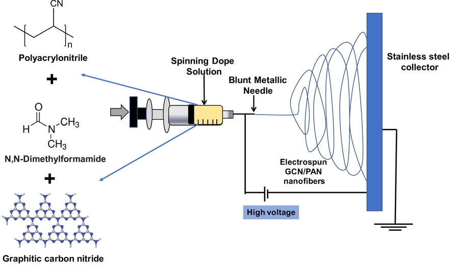
Fabrication of electrospun GCN/PAN nanofibres using electrospinning technique.
2.2.2 Characterisation
The surface morphology of the electrospun GCN/PAN nanofibres was examined using field-emission scanning electron microscopy (FESEM, Hitachi High-Tech. Co., Hitachi SU8020) and high-resolution transmission electron microscopy (HRTEM, Hitachi High-Tech. Co., Hitachi HT7700). The crystallinity of the GCN and nanofibres was examined using X-ray diffraction spectroscopy (XRD, Rigaku Asia and Pacific Pte. Ltd., Rigaku D/Max 2200 PC) with diffraction angle 2θ ranges between 2° and 80° with a scan rate of 2°/min. The measurements were conducted by employing Cu Kα radiation at the acceleration voltage of 40 kV and the acceleration current of 40 mA. The functional groups in GCN and nanofibres were characterised using Fourier transform infrared spectroscopy (FTIR, JASCO Inc., FT/IR-6100). The FTIR spectra were recorded at the wavenumber between 4000 and 600 cm−1. The elemental analysis of urea and GCN was investigated by a CHN corder (Yanaco MT-5). The optical structure of GCN was measured using UV–vis–NIR spectroscopy by transmission mode (Shidmadzu Co., UV-3101PC). The band gap energy of the GCN was estimated using the Kubelka–Munch function by plotting a graph of (αhv)2 versus hv, where α is the absorption coefficient and hv is the photon energy (Xu et al., 2017).
2.2.3 Photocatalytic measurement activity
HPAM solution (200 ppm) was freshly prepared by mixing HPAM with RO water overnight with stirring at room temperature. All photocatalytic measurements were conducted in a suspension mode using a photocatalytic reactor at room temperature as shown in Fig. 2. A UV light source with a wavelength region of 312 nm and wattage at 30 W was used for irradiation during the photocatalytic activity. The suspension solution containing photocatalyst (GCN powder, PAN nanofibres, GCN/PAN nanofibres) at 1 mg/L and HPAM solution was added in a 450 mL beaker and placed 15 cm from the light source. An air diffuser was supplied into the beaker to supply sufficient oxygen to the reaction. The samples were collected at every 30 min during the 180-min photocatalytic experiment. The degradation of organic compounds in HPAM was evaluated using total organic carbon (TOC) analysis carried out using TOC analyser (Shimadzu Co., TOC-LPCN). The TOC degradation (%) of the OPW solution was determined according to Eq. (1).
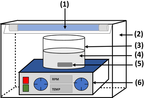
Schematic diagram of the GCN/PAN nanofibres in suspension photocatalytic reactor: (1) UV light source, (2) stainless steel reactor body frame, (3) Pyrex glass beaker, (4) GCN/PAN suspension in HPAM solution, (5) magnetic stirrer bar, and (6) magnetic stirrer.
3 Results and discussion
3.1 Characterisation
Fig. 3 shows the images of the synthesised GCN powder in pale yellow and the electrospun GCN/PAN nanofibres (Fig. 3a and d), and their morphological structures (Fig. 3b–f). Based on the SEM image (Fig. 3b), GCN shows a porous structure with a pore size of around 0.1–2 µm. At higher observation via TEM (Fig. 3c), individual GCN reveals irregular structures with a pore size of 20–100 nm. The porous structure represented by relatively darkbrightness could have resulted from the decomposition of urea during thermal treatment, which generated gas bubbles and induced the formation of porous structure (Alias et al., 2018). The porous structure of GCN provides high surface area, enhancing its mass transfer ability and photocatalytic activity (Zhang et al., 2014). Fig. 3e and f show the SEM and TEM images of GCN/PAN nanofibres. Since the molecular structure of PAN is similar with that of GCN, PAN shall have favourable miscibility and dispersity that are same with those of GCN. The SEM and TEM images of GCN/PAN nanofibres revealed that GCN/PAN nanofibres had been successfully fabricated by electrospinning technique and the resultant GCN-self-supporting nanofibre mats could be conveniently handled by hand. The nonwoven electrospun fibres were straight and smooth in infinite length structure with an average diameter of ≥200 nm. Based on the SEM images, the nanofibre mats have a network of highly well interconnected open pore structure with the size of several micrometres. Furthermore, the noduleless structure of GCN/PAN nanofibres indicates that the GCN particles were uniformly distributed along the PAN nanofibres surface.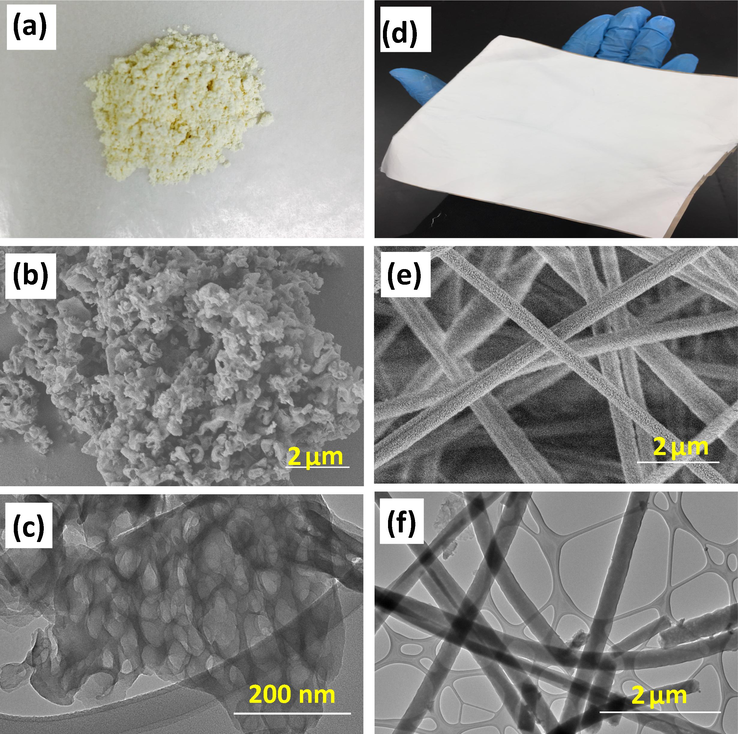
Images of (a) GCN powder and (d) GCN/PAN nanofibers, morphological characterisations of GCN powder (b & c) and GCN/PAN nanofibres (e & f) performed using SEM (b & e) and TEM (c & f).
Fig. 4(a) illustrates the crystalline structure of GCN. The X-ray diffraction (XRD) patterns show certain fractions of molecular arrangement in GCN with intense peaks at 2θ of 13.5° and 27.4°. The peak at 13.5° corresponds to the interlayer repeating of aromatic units, while the peak at 27.4° corresponds to the interlayer stacking of aromatic units (Chen et al., 2016). A successful embedment of GCN was observed in the XRD pattern of GCN/PAN nanofibres, where similar low intensity peaks at 25.5° and 15.6° were observed, corresponding to the crystalline structure of GCN. These low intensity peaks of GCN crystalline structures might be due to the low loading of GCN in PAN dope suspension.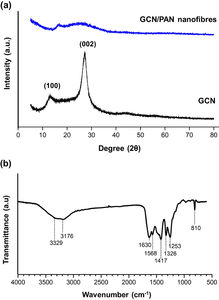
(a) The XRD patterns of GCN/PAN nanofibres and GCN, and (b) FTIR spectrum of GCN.
The functional groups related to GCN and CGN/PAN analysed using FTIR is shown in Fig. 4b. The FTIR spectrum of GCN obtained in this study is similar with the typical peaks of GCN spectra reported elsewhere (Mohamed et al., 2018; Kim et al., 2007). GCN mainly consists of various chemical bonds made from C and N atoms such as C—N bond, C≡N bond, N(—C)3, and C—NH—C bridges, even though it does not have any specific molecular structure (Alias et al., 2018). The weak peaks at 3176 and 3329 cm−1 correspond to the stretching modes of uncondensed amine groups, —NH2 or ⚌NH. Meanwhile, the peaks in the range of 900–1800 cm−1 are mainly attributed to the aromatic CN heterocycles which contain either fully condensed trigonal N(—C)3 or partially condensed bridging C—NH—C units (Ma et al., 2014). The three bands around 1417, 1326, and 1253 cm−1 are attributed to C—N stretching, while the absorption bands near 1630 and 1568 cm−1 correspond to C≡N stretching. Lastly, a single sharp band at 810 cm−1 originated from breathing of the tri-s-triazine units ring corresponds to the condensed CN heterocycles.
The result from elemental analysis shows that both urea and GCN are mainly composed of C and N as tabulated in Table 1. The presence of H is possibly attributed to the amino group in GCN. The carbon to nitrogen ratio (C/N) of bGCN was slightly higher than that of the urea precursor at 0.56. However, the H ratio significantly decreased which might be due to the increase of C/N resulted from the detachment of N atom as gas NH3. Moreover, the decrease of the H ratio was also probably due to the release of NH3 and H2O. The result indicates that the thermal decomposition of urea successfully formed GCN photocatalyst powder. However, elemental analysis of GCN/PAN nanofibre was not conducted because PAN consists of similar molecular structure with GCN. This result agrees with that of the XPS analysis of GCN from our previous study (Mohamed et al., 2018) where its composition mainly consists of C and N elements.
Sample
C
H
N
Others
C/N
Urea
20.0
6.7
46.7
26.6
0.43
GCN
33.1
2.2
59.3
5.4
0.56
The optical structures of GCN was examined using UV–vis absorption. As shown in Fig. 5(a), the diffuse reflectance spectrum of GCN exhibits an absorption edge around 440 nm, which signifies that GCN can absorb visible light with a wavelength shorter than 440 nm. As reported in Xu et al. (2015), the absorption edge of the GCN/PAN nanofibres has no significant different with that of the GCN powder. The band gap energy of GCN was estimated using the Kubelka–Munch function by plotting a graph of (αhv)2 versus hv, where α is the absorption coefficient and hv is the photon energy (Xu et al., 2017). A band gap energy of 2.72 eV was obtained from the intercept of the plot tangent.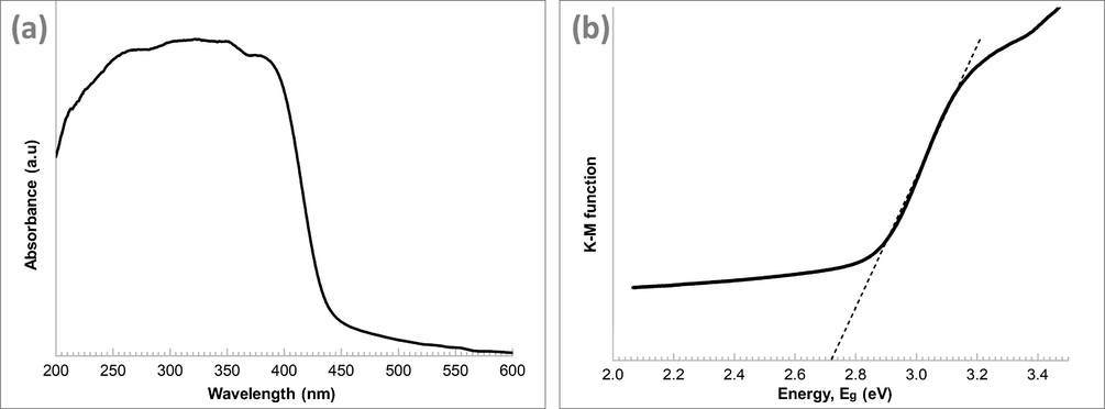
(a) Diffuse reflectance absorption spectra of GCN and (b) optical band gap plot transformed using Kulbelka–Munk function.
3.2 Photocatalytic degradation of HPAM solution
The removal efficiency of HPAM was investigated using HPAM water solution with an initial concentration of 20 ppm and were measured based on adsorption and photocatalytic degradation of HPAM in solution. Before irradiation, the mixture of HPAM and photocatalyst was stirred for 60 min in the dark to achieve adsorption equilibrium. This procedure was done to ensure that adsorption process does not interfere with the photocatalytic degradation of HPAM so that more accurate photocatalytic results can be obtained. After 60 min, the suspension of photocatalyst and HPAM solution was immediately irradiated with UV light to investigate the photocatalytic performance of GCN/PAN nanofibres.
Fig. 6 shows the degradation of HPAM by photodegradation of direct photolysis, GCN, PAN nanofibres and GCN/PAN nanofibres under UV light within 180 min. In the absence of photocatalyst, only 6.5% degradation of HPAM was observed. In the presence of pristine PAN nanofibres as photocatalyst, the degradation of HPAM increased to 65.1% after 180 min. The opening size of nanofibre mesh enables the HPAM molecules to permeate, colliding with the PAN nanofibre and eventually absorbed into the nanofibres that has favourable affinity to HPAM. It is well known that diffusion rates of small molecules increase with excess free volume of a polymer matrix (Freeman and Yampolskii, 2010). For GCN powder as photocatalyst, since GCN dispersed well in HPAM solution, the sample of suspension solution was centrifuged at 3000 rpm before TOC measurement was conducted to recover the GCN powder from HPAM solution. Compared to PAN nanofibres, 85.3% photodegradation of HPAM using GCN was observed. This high photodegradation indicates the effective photodegradation of pollutants by GCN in which it rapidly generated highly reactive species of HPAM organic contaminants. Furthermore, the fabricated GCN/PAN nanofibres was also convenient to be handled compared to the tedious separation of GCN powder after photocatalysis.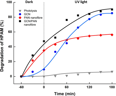
Degradation of HPAM under dark and UV light irradiation of direct photolysis, GCN, PAN nanofibre and GCN/PAN nanofibre.
Despite the good photodegradation of GCN, the well dispersity of GCN in aqueous system prohibits its real potential. In this study, we fabricated liquid permeable nanofibre which acts as a support to GCN particles that can overcome the issue of the tedious separation of GCN after photocatalytic process. Furthermore, the highest photodegradation of 90.2% was recorded by GCN/PAN nanofibres on HPAM, after 180 min UV light irradiation. This significant degradation of HPAM was the result of the synergetic effects of adsorption by PAN nanofibres and photocatalytic degradation by GCN embedded in PAN nanofibres. GCN/PAN nanofibres offer higher surface area that provides more photocatalytic active sites, thus producing more hydroxyl radicals and superoxide radical anions to enhance the degradation of HPAM. In addition, 10 wt% loading of GCN in PAN nanofibres is sufficient to perform excellent photocatalytic activity, similar to GCN powder that was directly dispersed into the HPAM suspension solution. The dose of photocatalyst is the influencing factor when characterising the degradation of an organic contaminant (Wang et al., 2017). Despite the amount of GCN powder used (1 mg/L), which is higher compared to GCN in PAN nanofibres (10% in 1 mg/L), the degradation using GCN powder was 5.4% lower, probably due to the agglomeration of GCN particles, which hindered and shielded the photocatalyst from UV light penetration.
The mechanism for the photocatalytic degradation of HPAM was possibly due to the existence of hydroxyl radical on the surface of GCN. There are three types of prominent species known as hydroxyl radicals (
), photogenerated holes (
), and superoxide radical anions (
) (Augugliaro et al., 2012). According to Al-Sabahi et al. (2018), photodegradation of HPAM generated several byproducts containing propionamide, acetamide and acetic acid. Under UV irradiation, HPAM is possibly converted to propionamide followed by the removal of CH3 group to form another byproduct of acetamide. In another part of HPAM, the compound of ∼CH3 reacts with free hydrogen ions (H+) to form acetic acid. Ammonia (NH3) is also formed during the degradation of HPAM which is photocatalytically converted into nitrite (NO2−) before further degraded to nitrate (NO3−). Fig. 7 proposes the mechanism of photodegradation of HPAM using GCN/PAN nanofibres under UV light irradiation. A complete mineralisation of HPAM also leads to the generation of harmless products, which are CO2 and water.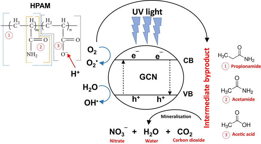
Proposed mechanism of photocatalytic degradation of HPAM using GCN/PAN nanofibres under UV light forming benign compound.
4 Conclusions
Graphitic carbon nitride (GCN) synthesised from urea was successfully embedded into the polyacrylonitrile (PAN) nanofibres using electrospinning technique. The fabricated electrospun GCN/PAN nonwoven nanofibres had highly interconnected open pores with infinite lengths as well as straight and smooth morphologies with an average diameter of ≥200 nm. The noduleless structure of GCN/PAN nanofibres indicates that GCN powders were uniformly distributed along the PAN nanofibres surface. Both GCN and PAN nanofibres had the photodegradation capability to degrade HPAM in aqueous under UV light irradiation. The PAN nanofibres effectively absorbed HPAM molecules inside the nanofibres. The incorporation of GCN into PAN nanofibres exhibited HPAM degradation of 90.2% under UV light irradiation. The incorporation of particles photocatalyst into polymer nanofibres using electrospinning technique is potentially promising and applicable to match a practical operation to meet the need of treatment of the produced water from polymer flooding.
Acknowledgements
N.H.A and J.J would like to express their sincere gratitude towards Malaysia Ministry of Higher Education for the research funding provided under UTM–HiCOE Research Grants (R.J090301.7846.4J184) and (R.J090301.7846.4J185), UTM for the financial support under Research University Grant (GUP) Tier 1 (Q.J130000.254616H43), Ministry of Education Malaysia for the financial support under Fundamental Research Grant Scheme (FRGS/1/2019/TK02/UITM/02/17) and Japan government for the Kurita Water and Environmental Foundation (KWEF) research grant (18P001). A part of this work was supported by “Nanotechnology Platform” (project No. A-17-NM-0208) of the Ministry of Education, Culture, Sports, Science and Technology (MEXT), Japan.
Declaration of Competing Interest
None.
References
- Polymer gelled technology to improve sweep efficiency in enhanced oil recovery: a literature review. Adv. Mater. Res.. 2015;1113:690-694.
- [CrossRef] [Google Scholar]
- Saccharomyces cerevisiae from baker’s yeast for lower oil viscosity and beneficial metabolite to improve oil recovery: an overview. Appl. Mech. Mater.. 2014;625:522-525.
- [CrossRef] [Google Scholar]
- Nanoemulsion applications in enhanced oil recovery and wellbore cleaning: an overview. Adv. Mater. Eng. Technol. III. 2015;754–755:1161-1168.
- [CrossRef] [Google Scholar]
- Photocatalytic nanofiber-coated alumina hollow fiber membranes for highly efficient oilfield produced water treatment. Chemical Engineering Journal. 2019;360:1437-1446.
- [CrossRef] [Google Scholar]
- Photocatalytic degradation of oilfield produced water using graphitic carbon nitride embedded in electrospun polyacrylonitrile nanofibres. Chemosphere. 2018;204:79-86.
- [CrossRef] [Google Scholar]
- Visible light photocatalytic degradation of HPAM polymer in oil produced water using supported zinc oxide nanorods. Chem. Eng. J.. 2018;351:56-64.
- [CrossRef] [Google Scholar]
- Overview on oxidation mechanisms of organic compounds by TiO2 in heterogeneous photocatalysis. J. Photochem. Photobiol. C Photochem. Rev.. 2012;13:224-245.
- [Google Scholar]
- Nanoparticles stabilized carbon dioxide foams in sandstone and limestone reservoir. Key Eng. Mater.. 2015;1119:170-174.
- [CrossRef] [Google Scholar]
- Sustainable technologies for water purification from heavy metals: review and analysis. Chem. Soc. Rev.. 2019;48:409-724.
- [CrossRef] [Google Scholar]
- Highly selective hydrogenation of furfural to furfuryl alcohol over Pt nanoparticles supported on g-C3N4 nanosheets catalysts in water. Sci. Rep.. 2016;6:28558.
- [CrossRef] [Google Scholar]
- Membrane Gas Separation. John Wiley & Sons Ltd; 2010. https://doi.org/10.1002/9780470665626.ch15
- Scientific research and field applications of polymer flooding in heavy oil recovery. J. Pet. Explor. Prod. Technol.. 2011;1:65-70.
- [CrossRef] [Google Scholar]
- CFD investigation of enhanced extra-heavy oil recovery using metallic nanoparticles/steam injection in a micromodel with random pore distribution. J. Pet. Sci. Eng.. 2019;174:374-383.
- [CrossRef] [Google Scholar]
- Facile preparation of MoS2 based polymer composites via mussel inspired chemistry and their high efficiency for removal of organic dyes. Appl. Surf. Sci.. 2017;419:35-44.
- [CrossRef] [Google Scholar]
- Surface functionalized SiO2 nanoparticles with cationic polymers via the combination of mussel inspired chemistry and surface initiated atom transfer radical polymerization: characterization and enhanced removal of organic dye. J. Colloid Interface Sci.. 2017;499:170-179.
- [CrossRef] [Google Scholar]
- Synthesis of polyacrylamide immobilized molybdenum disulfide (MoS2 @PDA @PAM) composites via mussel-inspired chemistry and surface-initiated atom transfer radical polymerization for removal of copper(II) ions. J. Taiwan Inst. Chem. Eng.. 2018;86:174-184.
- [CrossRef] [Google Scholar]
- Preparation of polyethylene polyamine@tannic acid encapsulated MgAl-layered double hydroxide for the efficient removal of copper(II) ions from aqueous solution. J. Taiwan Inst. Chem. Eng.. 2018;82:92-101.
- [CrossRef] [Google Scholar]
- Sugar palm nanofibrillated cellulose (Arenga pinnata (Wurmb.) Merr): Effect of cycles on their yield, physic-chemical, morphological and thermal behavior. Int. J. Biol. Macromol. 2019;123:379-388.
- [CrossRef] [Google Scholar]
- Novel ordered nanoporous graphitic C3N4 as a support for Pt-Ru anode catalyst in direct methanol fuel cell. J. Mater. Chem.. 2007;17:1656-1659.
- [CrossRef] [Google Scholar]
- Efficient removal of enhanced-oil-recovery polymer from produced water with magnetic nanoparticles and regeneration/reuse of spent particles. SPE Prod. Oper.. 2017;32:374-381.
- [CrossRef] [Google Scholar]
- A facile strategy for preparation of magnetic graphene oxide composites and their potential for environmental adsorption. Ceram. Int.. 2018;44:18571-18577.
- [CrossRef] [Google Scholar]
- Proton-functionalized two-dimensional graphitic carbon nitride nanosheet: an excellent metal-/label-free biosensing platform. Small. 2014;10:2382-2389.
- [CrossRef] [Google Scholar]
- In-depth understanding of core-shell nanoarchitecture evolution of g-C3N4@C, N co-doped anatase/rutile: efficient charge separation and enhanced visible-light photocatalytic performance. Appl. Surf. Sci.. 2018;436:302-318.
- [CrossRef] [Google Scholar]
- Mohd, T.A.T., Shukor, M.A.A., Ghazali, N.A., Alias, N., Yahya, E., Azizi, A., Shahruddin, M.Z., Ramleeh, N.A., 2014a. Relationship between foamability and nanoparticle concentration of carbon dioxide (CO2) foam for enhanced oil recovery (EOR). https://doi.org/10.4028/www.scientific.net/AMM.548-549.67.
- Mohd, T.A.T., Muhayyidin, A.H.M., Ghazali, N.A., Shahruddin, M.Z., Alias, N., Arina, S., Ismail, S.N., Ramlee, N.A., 2014b. Carbon dioxide (CO2) foam stability dependence on nanoparticle concentration for enhanced oil recovery (EOR). https://doi.org/10.4028/www.scientific.net/AMM.548-549.1876.
- Mobility investigation of nanoparticle-stabilized carbon dioxide foam for enhanced oil recovery (EOR) Adv. Mater. Res.. 2015;1119:90-95.
- [CrossRef] [Google Scholar]
- Mohd, T.A.T., Harun, A., Ghazali, N.A., Alias, N., Yahya, E., 2015b. Interfacial tension dependence on nanoparticle surface modification for stabilization of CO2 foam in EOR: an overview 1113, 8985. https://doi.org/10.4028/www.scientific.net/AMR.1113.637.
- Supported graphene oxide hollow fibre membrane for oily wastewater treatment. AIP Conf. Proc. 2017:020008.
- [CrossRef] [Google Scholar]
- Demulsification of crude oil in water (O/W) emulsions using graphene oxide demulsification of crude oil in water (O/W) emulsions using graphene oxide. IOP Conf. Ser. Mater. Sci. Eng.. 2018;458:012023.
- [CrossRef] [Google Scholar]
- Adsorption kinetics of methylene blue dyes onto magnetic graphene oxide. J. Environ Chem. Eng.. 2018;6:2803-2811.
- [CrossRef] [Google Scholar]
- Biodegradation for hydrolyzed polyacrylamide in the anaerobic baffled reactor combined aeration tank. Ecol. Eng.. 2015;84:121-127.
- [CrossRef] [Google Scholar]
- Photocatalytical visbreaking of wastewater produced from polymer flooding in oilfields. Colloids Surf. A Physicochem. Eng. Asp.. 2006;287:170-174.
- [CrossRef] [Google Scholar]
- Photoelectrocatalytic degradation of partially hydrolyzed polyacrylamide using a novel particle electrode. RSC Adv.. 2017;7:55496-55503.
- [CrossRef] [Google Scholar]
- Experimental investigation on improved heavy oil recovery by air assisted steam injection with 2D visualized models. Fuel. 2019;252:109-115.
- [CrossRef] [Google Scholar]
- In situ structural modification of graphitic carbon nitride by alkali halides and influence on photocatalytic activity. RSC Adv.. 2017;7:32592-32600.
- [CrossRef] [Google Scholar]
- Visible-light responsive electrospun nanofibres based on polyacrylonitrile-dispersed graphitic carbon nitride. RSC Adv.. 2015;5:86505-86512.
- [CrossRef] [Google Scholar]
- Nanoemulsion formulation using biodegradable oil in enhance oil recovery (EOR) Appl. Mech. Mater.. 2015;754–755:1098-1101.
- [CrossRef] [Google Scholar]
- Flooding with biopolymer from microbes derived from mushroom and cabbage to enhance sweep efficiency in enhanced oil recovery. Adv. Mater. Res.. 2015;1113:492-497.
- [CrossRef] [Google Scholar]
- Desalination of produced water using bentonite as pre-treatment and membrane separation as main treatment. Proc. - Soc. Behav. Sci.. 2015;195:2094-2100.
- [CrossRef] [Google Scholar]
- Facile preparation of carbon nanotubes based carboxymethyl chitosan nanocomposites through combination of mussel inspired chemistry and Michael addition reaction: characterization and improved Cu2+ removal capability. J. Taiwan Inst. Chem. Eng.. 2016;68:446-454.
- [CrossRef] [Google Scholar]
- Rapid synthesis of MoS2-PDA-Ag nanocomposites as heterogeneous catalysts and antimicrobial agents via microwave irradiation. Appl. Surf. Sci.. 2018;459:588-595.
- [CrossRef] [Google Scholar]
- Surface modification and drug delivery applications of MoS2 nanosheets with polymers through the combination of mussel inspired chemistry and SET-LRP. J. Taiwan Inst. Chem. Eng.. 2018;82:205-213.
- [Google Scholar]
- Preparation of amine functionalized carbon nanotubes via a bioinspired strategy and their application in Cu2+ removal. Appl. Surf. Sci.. 2015;343:19-27.
- [Google Scholar]
- Mussel-inspired fabrication of functional materials and their environmental applications: progress and prospects. Appl. Mater. Today. 2017;7:222-238.
- [CrossRef] [Google Scholar]
- Enhancement of visible light photocatalytic activities via porous structure of g-C3N4. Appl. Catal. B Environ.. 2014;147:229-235.
- [CrossRef] [Google Scholar]


