

Translate this page into:
Elaboration of carbon paste electrode containing pentadentate Nickel-(II) Schiff base complex: Application to electrochemical oxidation of thiosulfate in alkaline medium
⁎Corresponding author. zerroual@yahoo.fr (Larbi Zerroual)
-
Received: ,
Accepted: ,
This article was originally published by Elsevier and was migrated to Scientific Scholar after the change of Publisher.
Peer review under responsibility of King Saud University.
Abstract
A Nickel Schiff base complex, insoluble in water, was synthesized and used as modifier. A Nickel Schiff base modified carbon paste electrode MCPE was build. The electrodes were characterized by scanning electron microscopy (SEM), energy dispersive X-Ray spectroscopy (EDXS), cyclic voltammetry and chronoamperometry. The modifier is elctroactive, a well defined redox couple of NiIII/NiII in alkaline medium was made in evidence. It presents a quasi-reversible system with electron transfer coefficient (0.38) and electron transfer rate of 4.5 s−1. The electrogenerated NiIII species on the surface of the electrode act as an excellent catalyst toward thiosulfate oxidation reaction with a chemical rate constant Kh equal to 23,6 M−1s−1. The different techniques involved in this study qualify our modified electrode as sensitive, reliable and very stable for thiosulfate analysis.
Keywords
Carbon paste electrode
NiII-Schiff base complex
Modified carbon paste electrode
Cyclic voltammetry
Thiosulfate oxidation

1 Introduction
Thiosulfate is a prime pollutant resulting from photographic, paper and textile industries. It is, therefore, necessary to develop a sensitive, fast, low cost and analytical method for its determination and decomposition (Wiberg et al., 2001). Several methods such as iodometry are useful but take much time and are not reliable (Sörbo, 1957; Miura and Koh, 1985). Electrochemical analytical methods present a good choice due to the simplicity, time saving and low cost (Nosuhi and Nezamzadeh-Ejhieh, 2017). The electro-catalytic oxidation of thiosulfate (TS) was well investigated using noble metal based electrodes such as platinum and gold. However due to the high cost, oscillatory behavior and non linear phenomenon observed during the electro-oxidation reaction of TS on platinum surface (Du et al., 2006) and the leaching of gold by TS anion (Aylmore and Muir, 2001), it is preferable to develop more stable and low cost electrode materials. Chemically modified electrodes were pioneered by Lane, Hubbard, Murray and Miller (Watkins et al., 1975; Lane and Hubbard, 1973; Moses et al., 1975) and then extensively used by several researchers as strong tools for synthesis, electro-catalysis (Merz, 1990; El-Shafei, 1999; Ourari et al., 2017b) Analysis and detection (Sharafzadeh and Nezamzadeh-Ejhieh, 2015). Metal hexacyanoferrate films are examples of well studied chemically modified electrodes (de Tacconi et al., 2003), due to their simple preparation method (de Mattos et al., 2000), low cost and excellent electro-catalytic activity toward several chemical reactions (Ghaffarinejad et al., 2012; Ghica et al., 2013), as hydrazine, ascorbic acid and thiosulfate oxidation (Chen, 1996; Wang et al., 2001; Zhou et al., 1993). Carbon is the material of choice as a conductive (Yang et al., 2011), chemically inert support with very rich crystalline and amorphous forms (Zhang et al., 2007); it exhibits excellent chemical and physical properties (Mestl et al., 2001), such as large surface area and excellent adsorption properties (Julkapli and Bagheri, 2015; Lam and Luong, 2014; Li et al., 2016).
Carbon paste electrodes were pioneered and described by Adams since 1958 (Adams, 1958), among chemically modified electrodes, they have practical advantages including; ease of preparation and regeneration, strong tool to evaluate different modifiers, excellent electric properties (Ahmadi and Nezamzadeh-Ejhieh, 2017; Sharafzadeh and Nezamzadeh-Ejhieh, 2015), which make them actively developed by several researchers (Sheikh-Mohseni and Nezamzadeh-Ejhieh, 2014), building a useful platform for many applications (Arduini et al., 2012; Malha et al., 2016, 2013; Ourari et al., 2017a, 2017b, 2015).
We report in this work the use of carbon paste Nickel Schiff base complex modified electrode as reliable and sensitive electrode material for the analysis of thiosulfate. Our electrode material was elaborated by mixing a water insoluble Nickel Schiff base complex with powder, the (N,N’-bisalicylidenepropylenetriamine) NiII complex was previously synthesized (Ourari et al., 2015) then characterized as single crystal by X-ray diffraction (Charef et al., 2015). The modified carbon paste electrode was characterized by scanning electron microscopy (SEM), energy dispersive X-Ray spectroscopy (EDXS), cyclic voltammetry and chronoamperometry. In alkaline medium a well defined NiIII/NiII redox couple was recorded and a linear dependency of catalytic current was observed after addition of thiosulfate in the solution. The electrode has excellent sensitivity, good selectivity and remarkable stability.
2 Experimental
2.1 Chemicals
All chemicals were obtained from commercial sources and were used as received without any further purification. All solvents, absolute ethanol and dichloromethane are obtained from Fluka while N, N’-bis (3-aminopropyl) amine and salicylaldehyde are purchased from Sigma Aldrich. Nickel acetate tetrahydrated and NaOH were obtained from Fluka and Na2S2O3 in analytical grade from Merck.
2.2 Instrumentation
Electrochemical experiments were carried out using a 301/10 Potentiostat / Galvanostat type PGZ 301-Voltalab 10 Radiometer with PC work station and electrochemical interface IMT 301 with Volta Master 4 software. An electrochemical standard three-electrode cell of 10 ml was used. Potentials are referred to a (Hg/Hg2Cl2) saturated with KCl reference electrode. A Platinum wire was used as counter electrode. The different electrodes were examined using a Hitachi SU 8000 cold field emission scanning electron microscope.
2.3 Preparation of Ni II-L Nickel Schiff base complex
The Nickel-(II) [N,N’-bis(Salicylidenepropylenetriamine)] complex (NiII-L) was prepared according to the literature (Ourari et al., 2015; Charef et al., 2015) A mixture of the Schiff base (1 mmol) and the metal salt (1 mmol) [Ni (OAc) 2·4H2O], in 25 ml of ethanol was refluxed for 1–2 h. After cooling the mixture a greenish solid product was precipitated, collected by filtration, washed several times with hot ethanol and distilled water, then dried in air. The obtained Ni complex NiII-L is soluble in most organic solvents and insoluble in water.
2.4 Elaboration of the electrode
2.4.1 Carbon paste electrode
Carbon paste electrodes were prepared by mixing carbon powder with solid paraffin wax in the ratio 70/ 30 (w/w) respectively. Carbon powder was used as electric conductive support and paraffin wax as binder. These materials must be carefully mixed in an Agate mortar, to obtain a carbon paste sufficiently homogeneous for practical electrochemical uses. In our case, the composite material was filled in a syringe body of polyethylene (3 ml) in the side of needle (depth 3 mm, inner diam. 2 mm) and the electric contact is ensured by introducing a copper wire from the piston side as shown in Scheme 1.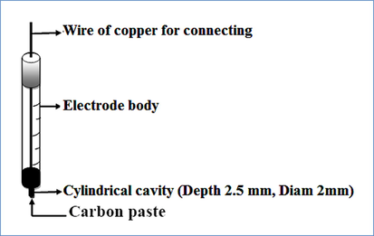
Carbon paste electrode used for electrochemical studies and electrocatalysis applications.
2.4.2 Modified carbon paste electrode (MCPE)
The modified carbon paste electrodes were prepared by the same manner than previously, masses of the Nickel Schiff base complex (NiII-L) equal to 2.5, 5, 7.5 and 10 mg were dissolved separately in 10 ml of dichlomethane each, then carbon powder was introduced to each solution as 97.5, 95, 92.5, and 90 mg respectively, the mixture was stirred for 1 h. After solvent evaporation the obtained solid was over night dried under vacuum to eliminate the residual solvent. In these formulations, the obtained modified carbon powders have the percentages of the modifier as 2.5, 5, 7.5, and 10% (w/w). For this, it was revealed that the most appropriate percentage for the electrochemical study was 5% of NiII-L. The MCPE was obtained by mixing the modified carbon powder with paraffin wax as binder in the ratio 70/ 30 (w/w) respectively for example we mix 70 mg of modified carbon powder with 30 mg of paraffin wax to obtain 100 mg of modified carbon paste ready for use(as shown in Scheme 2).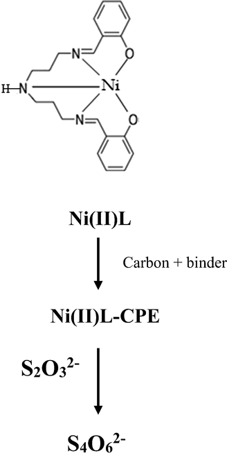
Ni (II)-Schiff base complex (Ni(II)L) mixed with carbon black and paraffin wax modified electrode used in electro-oxidation of thiosulfate.
3 Results and discussion
3.1 Characterization of new composite material
Fig. 1A shows the SEM micrographs of the modified carbon powder depicted at different magnitudes, presents a dark surface coated with well distributed clear particles with different shapes, having an average size less than 5 µm. Fig. 1 (B, C) shows the mapping of the different existing elements with EDX pattern, and confirms the presence of carbon with (95% w) which indicate that the most of the past constituted with carbon but it is less than expected, the presence of oxygen is not only from Schiff base but probably adsorbed from air on the carbon surface. Nickel presence is in good agreement with calculated amount; it should be around (0.75%w) it is present at (0.57% w) and well distributed on the surface. The elements analysis confirm the purity of carbon used in the preparation of the past, the small size of complex crystals and the good dispersion of nickel through carbon past, demonstrate the efficiency of the preparation protocol using CH2Cl2 as solvent.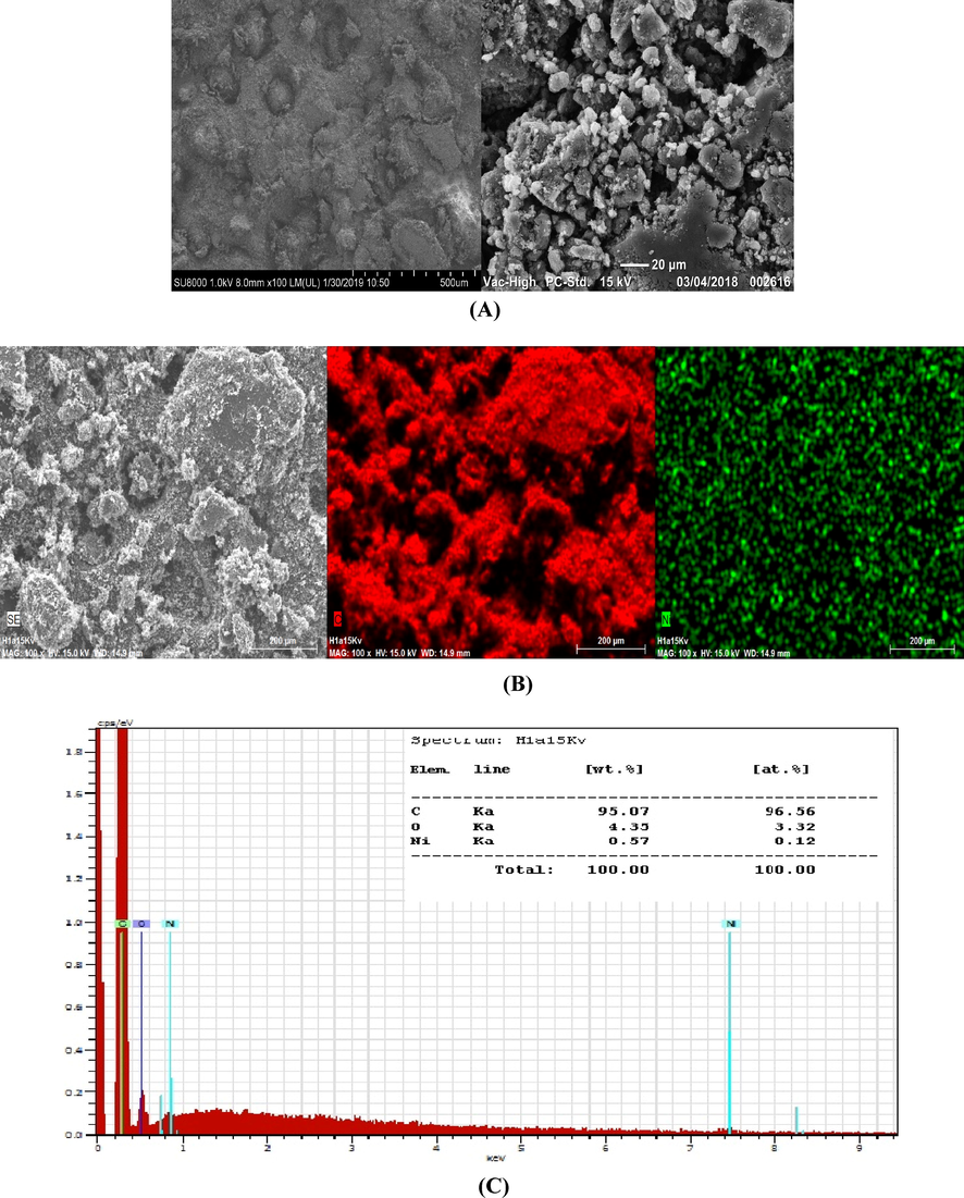
(A) SEM image of modified carbon powder taken at different magnifications. (B) SEM image of modified carbon powder with at medium magnification from left to right, SEM image without mapping, mapping of carbon element C first in right mapping of Nickel element. (C) EDX pattern of modified carbon powder with element composition.
3.2 Electrochemical behavior of the MCPE
Fig. 2 (A curves a and b) shows typical cyclic voltammograms (CV) of carbon paste electrode-CPE (without modifier) (curve a), and carbon paste electrode modified with Nickel Schiff base complex NiII-CPE (curve b) recorded in 0.1 M NaOH, between 0 and 650 mV/SCE at a scan rate of 15 mV.s−1. In the absence of NiII complex no electrochemical signal is recorded. In contrast, in the presence of NiII complex a pair of redox peaks appears at 312 and 206 mV/SCE respectively, in anodic and cathodic regions.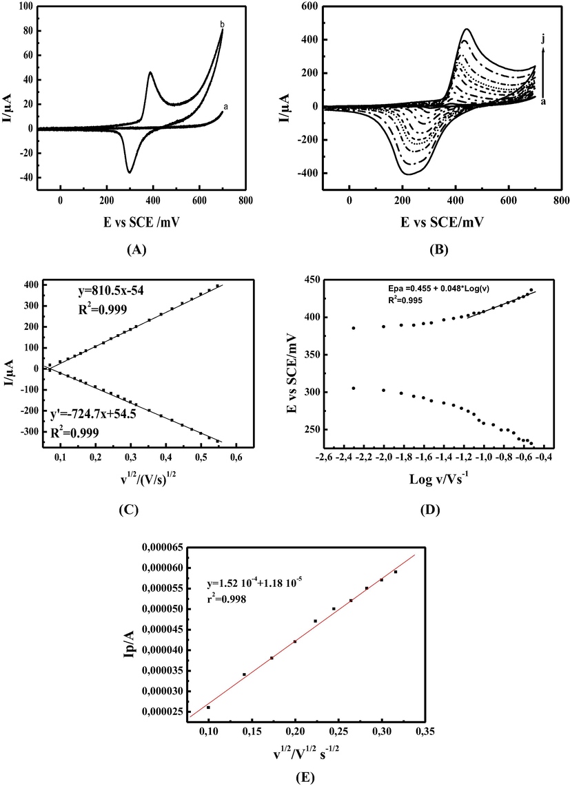
(A) Cyclic voltammograms of (a) CPE, (b) Ni(II)L-CPE recorded in 0.1 M NaOH at a scan rate of 15 mVs−1; (B) Cyclic voltammograms of MCPE in 0.1 M NaOH, at different scan rates: (a) 5, (b) 15, (c) 30, (d) 50, (e) 70, (f) 100, (g) 150, (h) 200, (i) 250, and (j) 300 mVs−1; (C) Anodic and cathodic peak currents (Ipa/c) versus square root of the scan rate (ν1/2); recorded in 0.1 M NaOH (D) Anodic and cathodic potentials (Epa/c) versus Logν. recorded in 0.1 M NaOH. (F) The plot of anodic pic current Ipa in A vs square root of scan rate in Vs−1 for the MCPE in 5 mM solution containing 1:1 ratio of K3Fe(CN)6/K4Fe(CN)6 + 0.1 M KCl, in the scan rate range from 15 to 100 mVs−1.
These two peaks correspond to the NiII/NiIII redox couple (Di Girolamo et al., 2019).
The electrochemical reaction may be written according to Eq. (1):
During the forward scan, the anodic peak corresponds to the oxidation reaction of [NiII-L(OH)]− (NiII) and leads [NiIII-L(OH)] (NiIII) species. Whereas during the reverse scan the cathodic peak is assigned to the reduction of [NiIII-L(OH)] to [NiII-L(OH)]− according to Eqs. (2) and (3) respectively.
The current values associated to this redox process are 45 µA for the anodic peak IPa and −36 µA for the cathodic one IPc, while the peak-to-peak separation ΔEP is equal to 92 mV indicating that this redox system is not Nernstian but it is rather quasi-reversible (Godwin and Lyons, 2013; Neiva et al., 2016). By varying the scan rate in the range between 5 and 300 mV.s−1 (Fig. 2B), the recorded voltammograms show a continuous increasing of both anodic and cathodic peak currents (ipa, ipc) accompanied with a shifting of anodic and cathodic peak potentials to a positive and negative values respectively, enlarging the peak-to-peak difference ΔEP. The ipa/ipc ratios are systematically higher than unity. From these results, we can conclude that the redox couple NiII/NiIII is in accordance with a slow electrochemical process. The linear dependency of anodic and cathodic peak currents (ipa, ipc) with the square root of the scan rate (v1/2) Fig. 2 (curve C) can be attributed to an electrochemical activity of Nin+ active species controlled by surface bound redox species (Abdel Hameed and Medany, 2017; Amani-Beni and Nezamzadeh-Ejhieh, 2018). Furthermore, the anodic and cathodic peak potentials (Epa, Epc) are proportional to the logarithm of the scan rate (Logν) as illustrated in Fig. 2 (curve D). These results are in accordance with those reported in the (Nosuhi and Nezamzadeh-Ejhieh, 2018; Tamiji and Nezamzadeh-Ejhieh, 2019) expressing probably an EC mechanism, due to the need of hydroxide ions for a charge compensation inducing a limitation of the charge transfer.
Our modified electrodes were fabricated from a composite material as mentioned, loading of the surface by electro-active species like NiII-L could not be homogeneous. The geometric surface area of the electrode surface is equal to 0.0314 cm2 (Id = 1 mm) whereas the effective surface area was 0.0436, for its estimation CVs of MCPE at different scan rate were recorded in 5 mM solution containing 1:1 ratio of K3Fe(CN)6/ K4Fe(CN)6 + 0.1 M KCl, the diffusion coefficient (D) value for K4Fe(CN)6 in similar conditions has been reported about 6.56 10−6 cm2 s−1 (Konopka and McDuffie, 2002), based on the plot of anodic pic current versus square root of scan rate and the reported (D) value (Fig. 2E), the resulting line equation is y = 1.52 10−4 + 1.18 10−5, r2 = 0.998, based on Randles-sevcik equation the effective surface area was calculated equal to 0.0436 cm2. The surface coverage can be estimated from the equation Eq. (4)
The integration of charge under the oxidation wave at slow scan rate (15 mVs−1) gives a quantity of charge equal to 0.24 mC.
With Q the quantity of charge calculate previously, n the number of exchanged electron equal to 1, F the Faraday constant and A the effective surface area equal to 0.0436 cm2 after calculation the surface loading was estimated to 5.7 10−8 mol.cm−2. By plotting the EPa vs Logv a linear behavior was shown for scan rate below 80 mVs−1 with line equation of y = 0.455 + 0.048x, R2 = 0.995. Basing on Laviron theory (Laviron, 1979; Laviron and Roullier, 1980) the transfer coefficient α was determined as given below:
The slope resulting from the line equation is presented in Fig. 2D:, for a scan rate ≥ 80 mV.s−1, the slope is b/2 where b is leading to a value of 0,048 V decade−1.
ks can be determined from Eq. (5):
3.3 Electro-catalytic oxidation of thiosulfate
The oxidation of thiosulfate was extensively studied in the literature using different modified electrodes. Formally, when this oxidation is occurred in alkaline medium using our modified electrode may be summarized by Eq.7:
However, the adsorbed intermediate species are not clearly known. The formation of tetrathionate S4O62− is more favored at low potential and high pH (Feng et al., 1995); Using CPE in 0,1M NaOH and in presence of 10 mM of thiosulfate Fig. 3 (A, curve a), the thiosulfate oxidation reaction takes place at around 1 V/SCE. By using MCPE in presence of thiosulfate its oxidation reaction was observed at 420 mV/SCE with a gain in potential value around 600 mV compared to CPE only. In addition, a significant current was recorded at slightly more positive potential compared to that obtained in the absence of TS Fig. 3 (A, curve band c), representing a strong catalytic activity of the MCPE toward thiosulfate oxidation reaction (Keivani et al., 2017). A full recovery of cathodic current ipc was observed during the reverse scan. The effect of the concentration of thiosulfate on MCPE response was investigated. Fig. 3 (B, curve a) shows the voltammograms plotted at a scan rate of 15 mV.s−1 at a concentration range varying from 0 to 50 mM. The anodic peak current increases by increasing the concentration of TS. The peak potential shifts slightly to positive directions, demonstrating the kinetic limitation of electro-oxidation process. In the studied concentration range the electro-catalytic peak current increases linearly with the concentration as shown in Fig. 3 (B, inset II). The cathodic current was fully recovered, which can be justified by the poor adsorption affinity of thiosulfate to the active sites. The thiosulfate radical anion S2O3.– is probably formed on the electrode surface as clarified by the equations below:
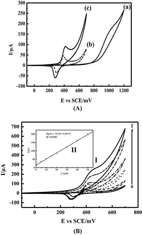
(A) Electrochemical responses for (a) CPE, in alkaline solution 0.1 M NaOH and 15 mVs−1 as scan rate in presence of 10 mM of thiosulfate; (b) NiIIL-CPE in alkaline solution 0.1 M NaOH and absence of thiosulfate; (c) NiIIL-CPE in alkaline solution 0.1 M NaOH and in presence of 10 mM of thiosulfate. (B): (I) Cyclovoltammograms obtained with modified electrode MCPE for electrocatalytic oxidation of thiosulfate in 0.1 M NaOH at scan rate 15 mVs−1 using various concentrations of thiosulfate: (a) 0, (b) 5, (c) 15, (d) 20, (e) 40, and (f) 50 mM, (II) Inset: the variation of anodic peak currents versus Thiosulfate concentration.
To understand the kinetic of the thiosulfate electro-catalytic oxidation in 0.1 M NaOH at MCPE surface, the effect of scan rate was investigated in the range between 15 and 100 mV.s−1 at relatively low concentration 10 mM as illustrated in (Fig. 4 A curve I). The recorded curves show an increase of the peak current with a shifting of the peak potentials to more anodic value, the catalytic peak current have a linear dependency with the square root of scan rate which indicates the diffusion controlled process (Fig. 4A inset II). At a concentration of 50 mM as shown in (Fig. 4B) the shape of the voltammogram was significantly changed, the plot of the normalized anodic peak current versus scan rate shown in (Fig. 4C), the normalized current was decreased to reach a constant level at higher scan rates, indicating a kinetic controlled process with a regenerative mechanism of the NiIII active species. The adsorbed thiosulfate at the electrode surface reacts chemically with NiIII and leads to NiII. The NiII species obtained undergo further electro-oxidation at the applied potential and regenerate NiIII active species again via an EC process as illustrated in the catalytic cycle (given in Scheme 3).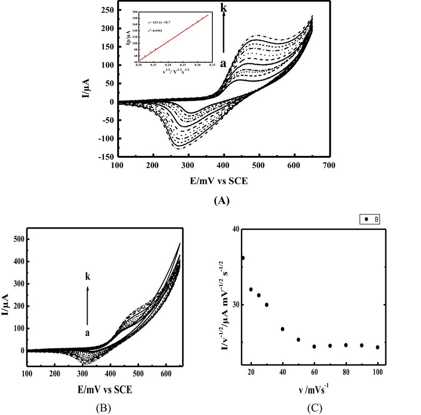
(A): (I) Cyclovoltammograms of modified electrode MCPE obtained in presence of 10 mM thiosulfate and 0.1 M NaOH at different scan rates ν: (a) 15, (b) 20, (c) 30, (d) 40, (e) 50 (f) 70, (g) 100, and (h)125 mVs−1; (II) Inset: the variation of anodic peak currents versus square root of scan rate (B): (I) Cyclovoltammograms of modified electrode MCPE obtained in presence of 50 mM thiosulfate and 0.1 M NaOH at different scan rates ν: (a) 15, (b) 20, (c) 30, (d) 40, (e) 50 (f) 70, (g) 100, and (h) 125 mVs−1. (C): The normalized anodic peak current versus scan rate.
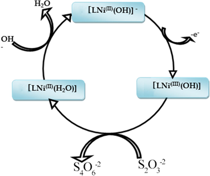
Proposed catalytic cycles of Ni (II)-Schiff base complex (Ni(II)L) toward thiosulfate electro-oxidation reaction.
In order to study the mass transfer kinetics and estimate the heterogeneous catalytic rate constant Kh, chronoamperometry was used and chronoamperograms were recorded by setting our MCPE potential at 600 mV/SCE in absence (Fig. 5A curves a) and in presence of TS in the range of 2 to 50 mM in 0.1 M NaOH, (Fig. 5A, curves b-h). The transient current increased upon increasing TS concentration. As shown in (Fig. 5B) by plotting net current with respect to the minus square root of time a linear dependency from line equation y = 182.6 x + 23.04, r2 = 0.999 was observed, obeying Cottrell law By applying Cottrell’s equation. Eq. (10)
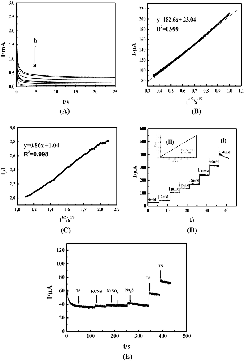
(A): Chronoamperogramm of MCPE in 0.1 M NaOH at 600 mV/SCE and different concentration of thiosulfate. (a) 0, (b) 2, (c) 5, (d) 15, (e) 20, (f) 30, (g) 40, and (h) 50 mM. (B): Dependency of the net current on the minus square root of time in 0.1 M NaOH and 10 mM TS. (C): Dependency of the Ic/I on the square root of time. In 0.1 M NaOH and in absence and presence 10 mM TS. (D): (I) Chronoamperogram of MCPE in 0.1 M NaOH at 600 mV/SCE and after successive addition of thiosulfate. (a) 0, (b) 2, (c) 5, (d) 15, (e) 20, (f) 30, (g) 40, (h) 50 mM. (II) Inset: Dependency of transient current on the thiosulfate concentration. (F): Chronoamperogram of MCPE in 0.1 M NaOH at 600 mV/SCE firstly in presence of 5 mM TS and after successive addition of 500 µM SCN–, SO32− and S2– interferon’s respectively, followed by twice successive addition of 2.5 mM TS.
To evaluate sensing capability of our MCPE, a typical amperometric signals recorded during successive additions of TS to 0.1 M NaOH solution at applied potential of 600 mV/SCE as shown in (Fig. 5D curves I). Under slow stirring the electrode responses were quite rapid and proportional to TS concentration. (Fig. 5D inset II) shows the calibration curve showing the amperometric current versus TS concentration, from the slope in the line equation
y = 7.12x + 1.34, r2 = 0.999 our MCPE sensitivity equal to 7.12 µA.mM−1 taking in account he geometric surface 0.0314 cm2 the sensitivity is 226.75 µA mM−1 cm−2.
The interference studies
Under optimal conditions, the interference of some compounds such as NO3–, Cl–, SO42−,S2–, SCN–, SO32−, K+ on the oxidation of 5 mM TS in 0.1 M NaOH at 600 mV vs SCE has been evaluated. It can be found that most ions such as NO3–, Cl–, SO42−, K+, did not show any interference effect during the determination of TS by using MCPE. However, 10-fold SCN– and 10-fold SO32− and S2– 10-fold were found to have noticeable interference in TS determination on the MCPE, (Fig. 5E) shows amperometric responses of MCPE in 0.1 M NaOH in the presence of 5 mM TS after successive addition of 500 µM SCN–, SO32− and S2–. These results suggest that MCPE can be successfully used to measure TS concentration in the presence of a variety of possible interfering substances.
3.4 Electrode stability
The modified carbon paste electrode (MCPE) studied in this work shows a good stability, after 7 month has been stored in ambient conditions, the electrode responds still remained. During cycling between 0 and 600 mV/SCE in 0.1 M NaOH, 10 mM TS at 15 mVs−1 for 200 cycles (Fig. 6A), the catalytic pic current remain stable with slight decrease to 96.71% of its initial value. As shown (Fig. 6B). The chronoamperogram of TS at a concentration of 10 mM in the time span of 90 min shows after an initial decrease a stabilization of the current indicating a good stability toward TS oxidation, by switching the potential between 0 mV vs SCE for 10 s and 600 mV vs SCE for 30 s in 0.1 M NaOH and 15 mM TS the chronoamperometric response shows stable signal during 30 cycles (Fig. 6C). The above results indicate no poisoning of the catalyst by the oxidation product. This electrochemical behavior may be explained by the stability of Nickel Schiff base complex in the working conditions.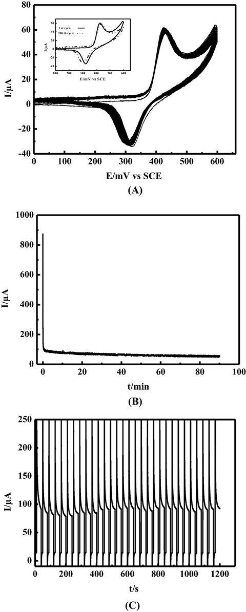
(A): 200 successive CVs cycles of modified electrode MCPE obtained in presence of 10 mM thiosulfate and 0.1 M NaOH at scan rate 15 mVs−1. Inset: the 1st and 200th cycles. (B): Chronoamperogramm of MCPE in 0.1 M NaOH at 600 mV/SCE and 10 mM TS for 90 min electrolysis. (C): 30 successive chronoamperometric cycles of MCPE in 0.1 M NaOH and 15 mM TS by switching potential at 0 mV vs SCE for 10 s and at 600 mV vs SCE for 10 s.
Our results compared to the literature seem to be very interesting as illustrated by Table 1.
Electrode
Modifier
Epa
Kh (cm3 mol−1 s−1)
Sensitivity (µA mM−1)
Ref.
CPE
NiO/NPs/CPE
0,97V/SCE
-
-
(Keivani et al., 2017)
CPE
2,4-DDMA-NiO/NPs/CPEa
0,49V/SCE
6.41 105
115,6
(Keivani et al., 2017)
CPE
CuHCF-GNSb
0,75V/Ag-AgCl
5.02 102
1.21
(Chen, 1996)
CCE
NiHCF-CCEc
0.513V/Ag-AgCl
-
1.33
(Wang et al., 2001)
GCE
CoPCNFd
0,8V/SCE
5.61 105
-
(Sabzi, 2005)
CPE
Ni(II)-L/CPEe
0,42V/SCE
2.36 104
7.12
This work
4 Conclusion
A new modified electrode fabricated from a pentadentate Nickel (II)-Schiff base complex, incorporated in carbon paste, showed a good electro-catalytic activity towards oxidation of thiosulfate evidenced by higher peak current density.
The enhanced electro-catalytic performance is mainly due to the electro-generated Nickel(III) mediator on the electrode surface. The electrochemical study of its behavior in alkaline medium shows a good stability and negligible poisoning effect. An investigation about all probable oxidation products requires more effort and long time electrolysis, but due to the strength of S-S bend the main product of thiosulfate electro-oxidation is tetrathionate anion S4O62−. The different techniques involved in this study permit the calculation of the diffusion coefficient D and rate constant Kh. According to the obtained results, it is clear that the MCPE exhibits a good stability and sensitivity around 226.75 µA.mM−1.cm2 which qualifies it as a good sensing platform for determination of thiosulfate.
Acknowledgement
We gratefully aknowledge the “Direction Générale de Recherche (DGR)” for the financial support. The authors would like also to thank Professor Ali Ourari, from Faculté de Technologie, Université Ferhat Abbas-Sétif-1, Laboratoire d'Electrochimie, d'Ingénierie Moléculaire et de Catalyse Redox (LEIMCR), Sétif 19000, Algeria, for his help.
References
- Enhanced electrocatalytic activity of NiO nanoparticles supported on graphite planes towards urea electro-oxidation in NaOH solution. Int. J. Hydrog. Energy. 2017;42:24117-24130.
- [CrossRef] [Google Scholar]
- A comprehensive study on electrocatalytic current of urea oxidation by modified carbon paste electrode with Ni(II)-clinoptilolite nanoparticles: Experimental design by response surface methodology. J. Electroanal. Chem.. 2017;801:328-337.
- [CrossRef] [Google Scholar]
- NiO nanoparticles modified carbon paste electrode as a novel sulfasalazine sensor. Anal. Chim. Acta. 2018;1031:47-59.
- [CrossRef] [Google Scholar]
- Carbon black-modified screen-printed electrodes as electroanalytical tools. Electroanalysis. 2012;24:743-751.
- [CrossRef] [Google Scholar]
- Synthesis, characterization, X-ray structures, and biological activity of some metal complexes of the Schiff base 2,2′-(((azanediylbis(propane-3,1-diyl))bis(azanylylidene))bis(methanylylidene))diphenol. Polyhedron. 2015;85:450-456.
- [CrossRef] [Google Scholar]
- Electrocatalytic oxidation of thiosulfate by metal hexacyanoferrate film modified electrodes. J. Electroanal. Chem.. 1996;417:145-153.
- [CrossRef] [Google Scholar]
- Development of biosensors based on hexacyanoferrates. Talanta. 2000;52:791-799.
- [CrossRef] [Google Scholar]
- Metal hexacyanoferrates: electrosynthesis, in situ characterization, and applications. Chem. Mater.. 2003;15:3046-3062.
- [CrossRef] [Google Scholar]
- Investigating the electrodeposition mechanism of anodically grown NiOOH films on transparent conductive oxides. Electrochim. Acta. 2019;319:175-184.
- [CrossRef] [Google Scholar]
- Dynamic instabilities and mechanism of the electrochemical oxidation of thiosulfate. J. Phys. Chem. B. 2006;110:26098-26104.
- [CrossRef] [Google Scholar]
- Electrocatalytic oxidation of methanol at a nickel hydroxide/glassy carbon modified electrode in alkaline medium. J. Electroanal. Chem.. 1999;471:89-95.
- [CrossRef] [Google Scholar]
- Oxidation of thiosulfate to sulfate at glassy carbon electrodes. J. Electrochem. Soc.. 1995;142:2618.
- [CrossRef] [Google Scholar]
- Fundamentals of electrochemical analysis, Ellis Horwood series in analytical chemistry. Ellis Horwood; Halsted Press, a division of. Chichester : New York: Wiley; 1976.
- Effect of metal hexacyanoferrate films on hydrogen evolution reaction. J. Electroanal. Chem.. 2012;685:103-108.
- [CrossRef] [Google Scholar]
- Glucose oxidase enzyme inhibition sensors for heavy metals at carbon film electrodes modified with cobalt or copper hexacyanoferrate. Sens. Actuators B Chem.. 2013;178:270-278.
- [CrossRef] [Google Scholar]
- Enhanced oxygen evolution at hydrous nickel oxide electrodes via electrochemical ageing in alkaline solution. Electrochem. Commun.. 2013;32:39-42.
- [CrossRef] [Google Scholar]
- Graphene supported heterogeneous catalysts: An overview. Int. J. Hydrog. Energy. 2015;40:948-979.
- [CrossRef] [Google Scholar]
- An electrochemical strategy to determine thiosulfate, 4-chlorophenol and nitrite as three important pollutants in water samples via a nanostructure modified sensor. J. Colloid Interface Sci.. 2017;507:11-17.
- [CrossRef] [Google Scholar]
- Konopka, S.J., McDuffie, B., 2002. Diffusion coefficients of ferri- and ferrocyanide ions in aqueous media, using twin-electrode thin-layer electrochemistry [WWW Document]. https://doi.org/10.1021/ac50160a042.
- Carbon materials as catalyst supports and catalysts in the transformation of biomass to fuels and chemicals. ACS Catal.. 2014;4:3393-3410.
- [CrossRef] [Google Scholar]
- Electrochemistry of chemisorbed molecules. I. Reactants connected to electrodes through olefinic substituents. J. Phys. Chem.. 1973;77:1401-1410.
- [CrossRef] [Google Scholar]
- General expression of the linear potential sweep voltammogram in the case of diffusionless electrochemical systems. J. Electroanal. Chem. Interfacial Electrochem.. 1979;101:19-28.
- [CrossRef] [Google Scholar]
- General expression of the linear potential sweep voltammogram for a surface redox reaction with interactions between the adsorbed molecules: Applications to modified electrodes. J. Electroanal. Chem. Interfacial Electrochem.. 1980;115:65-74.
- [CrossRef] [Google Scholar]
- Nitrogen-doped porous carbon materials: promising catalysts or catalyst supports for heterogeneous hydrogenation and oxidation. Catal. Sci. Technol.. 2016;6:3670-3693.
- [CrossRef] [Google Scholar]
- Electrochemical characterization of carbon solid□like paste electrode assembled using different carbon nanoparticles. Electroanalysis. 2016;28:1044-1051.
- [CrossRef] [Google Scholar]
- Carbon black-modified electrodes as sensitive tools for the electrochemical detection of nitrite and nitrate. Electroanalysis. 2013;25:2289-2297.
- [CrossRef] [Google Scholar]
- Chemically modified electrodes. In: Steckhan E., ed. Electrochemistry IV, Topics in Current Chemistry. Berlin, Heidelberg: Springer; 1990. p. :49-90.
- [CrossRef] [Google Scholar]
- Carbon nanofilaments in heterogeneous catalysis: an industrial application for new carbon materials? Angew. Chem. Int. Ed.. 2001;40:2066-2068.
- [CrossRef] [Google Scholar]
- Spectrophotometric determination of micro amounts of thiosulfate by liberation of thiocyanate from mercury(II) thiocyanate. Anal. Chim. Acta. 1985;173:33-41.
- [CrossRef] [Google Scholar]
- Chemically modified tin oxide electrode. Anal. Chem.. 1975;47:1882-1886.
- [CrossRef] [Google Scholar]
- Nickel nanoparticles with hcp structure: Preparation, deposition as thin films and application as electrochemical sensor. J. Colloid Interface Sci.. 2016;468:34-41.
- [CrossRef] [Google Scholar]
- A sensitive and simple modified zeolitic carbon paste electrode for indirect voltammetric determination of nitrate. Ionics. 2018;24:2135-2145.
- [CrossRef] [Google Scholar]
- High catalytic activity of Fe(II)-clinoptilolite nanoparticales for indirect voltammetric determination of dichromate: Experimental design by response surface methodology (RSM) Electrochim. Acta. 2017;223:47-62.
- [CrossRef] [Google Scholar]
- Electrocatalytic reduction of nitrite and bromate and their highly sensitive determination on carbon paste electrode modified with new copper Schiff base complex. J. Electroanal. Chem.. 2017;797:31-36.
- [CrossRef] [Google Scholar]
- Elaboration of modified poly(NiII-DHS) films as electrodes by the electropolymerization of Ni(II)-[5,5′-dihydroxysalen] onto indium tin oxide surface and study of their electrocatalytic behavior toward aliphatic alcohols. Arab. J. Chem.. 2017;10:914-921.
- [CrossRef] [Google Scholar]
- Elaboration of new electrodes with carbon paste containing polystyrene functionalized by pentadentate nickel(II)-Schiff base complex – Application to the electrooxidation reaction of methanol and its aliphatic analogs. Electrochim. Acta. 2015;170:311-320.
- [CrossRef] [Google Scholar]
- Using of anionic adsorption property of a surfactant modified clinoptilolite nano-particles in modification of carbon paste electrode as effective ingredient for determination of anionic ascorbic acid species in presence of cationic dopamine species. Electrochim. Acta. 2015;184:371-380.
- [CrossRef] [Google Scholar]
- Modification of carbon paste electrode with Ni-clinoptilolite nanoparticles for electrocatalytic oxidation of methanol. Electrochim. Acta. 2014;147:572-581.
- [CrossRef] [Google Scholar]
- A colorimetric method for the determination of thiosulfate. Biochim. Biophys. Acta. 1957;23:412-416.
- [CrossRef] [Google Scholar]
- Electrocatalytic behavior of AgBr NPs as modifier of carbon past electrode in the presence of methanol and ethanol in aqueous solution: A kinetic study. J. Taiwan Inst. Chem. Eng.. 2019;104:130-138.
- [CrossRef] [Google Scholar]
- Amperometric determination of thiosulfate at a surface-renewable nickel(II) hexacyanoferrate-modified carbon ceramic electrode. Talanta. 2001;53:863-869.
- [CrossRef] [Google Scholar]
- Wiberg, E., Wiberg, N., Holleman, A.F., 2001. Inorganic chemistry, 1st English ed. ed. Academic Press ; De Gruyter, San Diego: Berlin ; New York.
- Porous carbon-supported catalysts for energy and environmental applications: A short review. Catal. Today, Catal. Energy Clean Environ.. 2011;178:197-205.
- [CrossRef] [Google Scholar]
- Nanocarbon as robust catalyst: mechanistic insight into carbon-mediated catalysis. Angew. Chem. Int. Ed.. 2007;46:7319-7323.
- [CrossRef] [Google Scholar]
- Electrocatalytic oxidation of thiosulfate on a modified nickel hexacyanoferrate film electrode. Fresenius J. Anal. Chem.. 1993;345:424-427.
- [CrossRef] [Google Scholar]


