

Translate this page into:
Electrospun aligned nanofibers: A review
⁎Corresponding authors. hao@qust.edu.cn (Chun-Cheng Hao), yunze.long@163.com (Yun-Ze Long)
-
Received: ,
Accepted: ,
This article was originally published by Elsevier and was migrated to Scientific Scholar after the change of Publisher.
Peer review under responsibility of King Saud University.
Abstract
Electrospinning (e-spinning) is famous for the construction and production of ultrafine and continuous micro-/nanofibers. Then, the alignment of electrospun (e-spun) nanofibers becomes one of the most valuable research topics. Because aligned fibers have more advantages over random fibers, such as better mechanical properties, faster charge transport, more regular spatial structure, etc. This review summarizes various electrospinning techniques of fabricating aligned e-spun nanofibers, such as early conventional methods, near-field e-spinning, and three-dimensional (3D) printing e-spinning. Among them, four auxiliary preparation methods (e.g., auxiliary solid template, auxiliary liquid, auxiliary electromagnetic field and auxiliary airflow), two collection modes (static and dynamic collection), and the controllability of near-field e-spinning and 3D printing e-spinning are highlighted. The representative applications depending on aligned nanofibers are classified and briefly introduced, emphasizing in the fields of 1D applications (e.g., field-effect transistor, nanochannel and guidance carrier), 2D applications (e.g., platform for gas detection, filter, and electrode materials storage), and 3D applications (e.g., bioengineering, supercapacitor, and nanogenerator). At last, the challenges and prospects are addressed.
Keywords
Nanofiber
Alignment
Near-field electrospinning
3D printing electrospinning
Micro-electro-mechanical application

1 Introduction
Electrospinning (e-spinning) is superior in the preparation of micro-/nanofiber structures, including one-dimensional (1D) nanofibers, two-dimensional (2D) fibrous membranes, and three-dimensional (3D) fibrous scaffolds, because of simple e-spinning devices, easy operation, low cost as well as widely-used nanofiber products. In the development history of e-spinning, especially in recent 20 years, it can be found that controllable preparation of nanofibers is very important for realizing various potential applications. Furthermore, excellent physical/chemical properties such as better mechanical properties, higher tensile ratio, faster charge transport, and more regular spatial structure, often tend to appear with controllable nanofibers over non-woven fabrics. Therefore, the alignment of e-spun nanofibers, as a representative of controllable preparation, has attracted much attention.
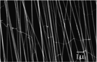
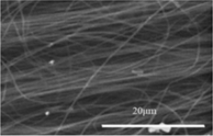
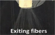
Beginning from the patent applied for by Formhals, e-spinning has had a history of nearly 90 years (Formhals, 1934). However, the re-recognition of e-spinning took place in the 1990 s due to the researches on polymer fibers (Reneker and Chun, 1996). Nowadays, e-spinning is experiencing a period of rapid development. Many e-spinning devices and processes have been developed to be more automatic and diversified to adapt to the commercialization of nanofiber-based applications. Current researches on e-spinning includes the design of e-spinning apparatus (in laboratory or factory), the study of spinning precursor (solution e-spinning and melt e-spinning), the preparation of different nanofiber aggregates, and the applications of e-spun nanofibers in different fields, etc. But no matter what any development, their prototypes remain unchanged, as shown in Fig. 1A. A solution container (a syringe with a needle) is used to store the spinning solution and a metal collector is used to collect nanofibers. Crucially, a direct-current (DC) high voltage power supply (DC HVPS) which can provide tens of kilovolts makes the three parts into an e-spinning system with the positive electrode connecting the needle and the negative electrode connecting the collector. Under the action of a strong electric field (∼1 kV/cm) between the needle and collector, the charged precursor solution completes the transformation to nanofibers largely experiencing four stages, as shown in Fig. 1B. Finally, disordered nanofibers are obtained on the grounded collector, as shown in Fig. 1C. Relatively speaking, the stages of solution jet and initial bending instability are easy to control. Under a series of auxiliary conditions (e.g., near-field electrospinning device with a 2D mobile station/collector), the corresponding aligned e-spun nanofibers can be collected, as shown in Fig. 1D.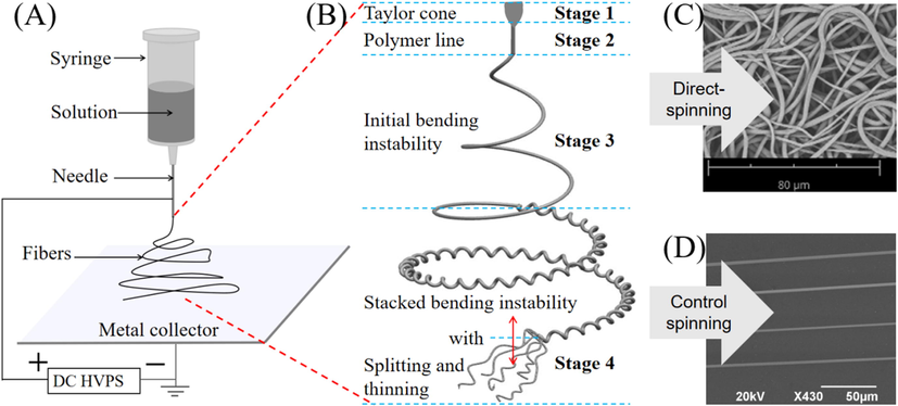
(A) Schematic diagram of e-spinning. (B) Four stages of enlarged fibers during e-spinning process. (C) Disordered fibers by conventional e-spinning device. (D) Aligned nanofibers by controlled/modified e-spinning device.
Up to now, the preparation technology of e-spun aligned nanofibers has been relatively mature, involving auxiliary solid template (Huang et al., 2003; Li et al., 2003; Yang et al., 2007; Dalton et al., 2005; Bazbouz and Stylios, 2008; Theron et al., 2001; Matthews et al., 2002; Katta et al., 2004; Zheng et al., 2015; Vaquette and Cooper-White, 2011; Zhao et al., 2013), auxiliary liquid (Smit et al., 2005; Teo et al., 2007; Li et al., 2021), auxiliary electromagnetic field (Gu et al., 2007; Li et al., 2016), and auxiliary airflow (McClure et al., 2012; Chen et al., 2016; Zhang et al., 2018), and some other methods (Conte et al., 2019; Hsu et al., 2020; Liu et al., 2012). The e-spun materials have also been developed from single polymer material to various polymer composite, metallic oxide, carbon fibers, and ceramics, etc. The development of alignment of e-spun nanofibers has three important stages. Most studies in its early stage mainly focus on the modification of fiber collector. Then, near-field e-spinning (NFES) or near-field direct-writing has emerged and been widely studied. Recently, 3D printing e-spinning has received the most and widespread attention. In this review, we briefly describe the development of e-spun aligned nanofibers and related potential applications (mainly in recent 5 years). Herein, NFES is known as the technology to open a new chapter for precise-deposition e-spinning and 3D printing e-spinning, the later is acclaimed as the most advanced e-spinning technology in additive manufacturing today. Finally, the current trends, challenges, and prospects are addressed.
2 Conventional methods
These strategies cover the most preparation methods of aligned e-spun nanofibers. According to the mode of auxiliary collection, it can be divided into seven categories, as shown in Table 1. These seven categories can also be more widely divided into two modes: Static collection and dynamic collection.
Method
No.
Diagram
Effect*
Reference
Auxiliary solid template
1
(Huang et al., 2003)
2
(Li et al., 2003; Yang et al., 2007)
3


(Dalton et al., 2005; Bazbouz and Stylios, 2008)
4
(Theron et al., 2001; Matthews et al., 2002)
5
(Katta et al., 2004)
6
(Zheng et al., 2015)
Patterned e-spinning
7
(Vaquette and Cooper-White, 2011)
8
(Zhao et al., 2013)
Auxiliary liquid
9
(Smit et al., 2005)
10
(Teo et al., 2007)
11
(Li et al., 2021)
Auxiliary electromagnetic field
12
(Gu et al., 2007)
13
(Li et al., 2016)
Auxiliary airflow
14

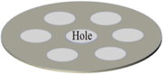
(McClure et al., 2012)
15
(Chen et al., 2016; Zhang et al., 2018)
Centrifugal e-spinning
16

(Wang et al., 2017)
17

(Li et al., 2011)
Post-treatment
18
(Conte et al., 2019; Hsu et al., 2020)
2.1 Static collection mode
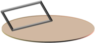
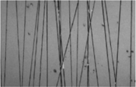
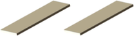
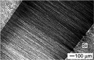
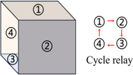
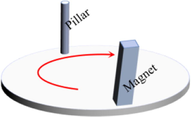
The so-called static collection is keeping the fiber generator and collector relatively stationary during the e-spinning process. To achieve alignment of e-spun nanofibers, changing the single planar collector is one of the options. Huang et al. obtained aligned polyethylene oxide (PEO) nanofibers by adding a frame on the traditional collector and keeping a certain angle (60°) placed (Huang et al., 2003) (method No. 1 in Table 1). The additional frame affects the distribution of the electric field, and thus determines the deposition path of the e-spun fibers. The results demonstrated that the alignment degree of nanofibers depended on the material of the frame (an aluminum frame is superior to a wooded frame). Li et al. (Li et al., 2003) and Yang et al. (Yang et al., 2007) replaced the traditional collector with double collectors placed side by side (method No. 2 in Table 1). Li et al. have utilized conductive Si stripes separated by a small gap (hundreds of micrometers to several centimeters) to achieve the fabrication of aligned nanofibers from poly(vinyl pyrrolidone) (PVP), polyacrylonitrile (PAN), TiO2/PVP, and a variety of other ceramics based on the tensile effect of an electric field between two plates on charged nanofibers (Li et al., 2003). Similarly, Yang et al. fabricated aligned poly(vinyl alcohol) (PVA) nanofibers by placing two magnets on a conventional device (Yang et al., 2007). However, it should be noted that a small number of magnetic nanoparticles (e.g., Fe3O4 nanoparticles, 0.22 wt%) need to be added to the polymer solution, and then the magnetized spinning solution could be pulled by the magnetic field in e-spinning. This described gap method is multifarious in form. For example, Teo et al. developed a gap method with steel blades instead of double collecting plates to control the electric field affecting fiber deposition and successfully obtained highly aligned polycaprolactone (PCL) nanofibers and fiber bundles (Teo and Ramakrishna, 2005). Aligned fibers can also be obtained with face-to-face collectors (method No. 3 in Table 1) (Dalton et al., 2005; Bazbouz and Stylios, 2008). Dalton et al. utilized grounded rings to complete the preparation of aligned PCL fibers (Dalton et al., 2005) and Bazbouz et al. utilized two copper disks to obtain aligned nylon 6 nanofibers (Bazbouz and Stylios, 2008). The above-mentioned methods are generally simple to operate and the devices are not complicated.
Patterned e-spinning also belongs to the type of static collection. Based on the different effects of collectors made of different materials on the electric field, two forms are introduced here. Patterned PCL nanofiber films were prepared by Vaquette et al. using conductive metal electrodes as collectors (Vaquette and Cooper-White, 2011) (method No. 7 in Table 1). Similarly, Zhao et al. also obtained patterned nanofibers using insulating substrates (Zhao et al., 2013) (method No. 8 in Table 1). It should be noted that when the insulating substrate is used as the fiber collector, it generally needs to be used together with a metal electrode. The two methods are mainly based on the influence of conductor/insulator on electric field distribution, which affects the deposition of charged fibers. Furthermore, the factors that could affect the alignment of nanofibers are not only the material of the collector, but also the shape and placement. The influence of these parameters is applicable to all preparation methods that achieve ordered alignment of nanofibers through self-assembly.
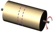
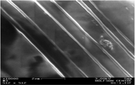
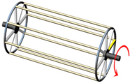
2.2 Dynamic collection mode
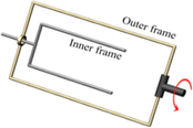
The so-called dynamic collection is keeping the relative motion between the fiber generator and the collector during e-spinning process. Among them, the most widely used method is the rotating cylinder collection (Theron et al., 2001; Matthews et al., 2002; Katta et al., 2004). Aligned collagen nanofibers were obtained by Matthews et al. utilizing a rotating mandrel (Matthews et al., 2002) and aligned PEO nanofibers were obtained by Theron et al. utilizing a rotating disk (Theron et al., 2001) (method No. 4 in Table 1). The difference between the two forms lies in the contact area of the collector surface. Another similar form is utilizing a rotating wire drum to obtain aligned nanofibers (Katta et al., 2004) (method No. 5 in Table 1). Particularly, Zheng et al. proposed a device with two-frame collector to fabricate highly aligned arrays of polystyrene (PS) nanofibers with array area>14 cm × 12 cm (the size of the inner frame), by keeping the inner frame fixed and outer framer rotating in e-spinning (Zheng et al., 2015) (method No. 6 in Table 1). Furthermore, twisted polymer fiber ropes (e.g., PS, PVDF, and PVDF/carbon nanotubes composite) were obtained from the aligned e-spun nanofibers. The key to the preparation of aligned nanofibers by the above methods is the control of the rotation speed of collectors. In general, when the collection speed is too slow, the degree of fiber alignment is poor, and when the collection speed is too fast, some fibers will be pulled and broken, but the high collection speed may make the fiber diameter thinner. In order to obtain high-quality aligned nanofibers, the spinning speed and collection speed must be nearly the same. Generally, the fiber collection speed is slightly larger than the spinning speed.
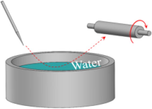
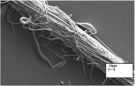
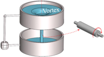
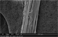
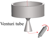
Another dynamic collection method is conducted by utilizing water/water flow, called the auxiliary liquid method (Smit et al., 2005; Teo et al., 2007; Li et al., 2021). Initially, Smit et al. prepared e-spun nanofiber yarns of PVDF, PAN, and PVA by a water reservoir collector cooperated with a take-up roller in 2005 (Smit et al., 2005) (method No. 9 in Table 1). Two years later, Teo et al. utilized a dynamic liquid support system that could produce a water vortex to fabricate continuous yarn of PVDF-co-hexafluoropropylene (Teo et al., 2007) (method No. 10 in Table 1). Recently, Li et al. fabricated PAN nanofiber bundles by a novel Venturi tube high-speed airflow drafting method (Li et al., 2021), due to the strong attractive force produced by the Venturi effect and aggregation of water vortex (method No. 11 in Table 1). In fact, the above-mentioned method makes comprehensive use of auxiliary liquid and auxiliary airflow. These three auxiliary liquid methods are suitable for preparing continuous fiber bundles, but the morphology is generally not ideal. Because the parameters involved cannot be accurately controlled in the process of orderly self-assembly of nanofibers by water flow or directional deposition by the effect of airflow on nanofibers.
Some research groups also prepared aligned e-spun nanofibers by auxiliary electromagnetic field method (Gu et al., 2007; Li et al., 2016). Gu et al. obtained twisted PEO nanofibers by applying a voltage of 220 V to each side of an auxiliary electrode to form a continuously rotating electric field (Gu et al., 2007) (method No. 12 in Table 1). Recently, Li et al. fabricated aligned and cross-aligned magnetic microfibers by a magneto-mechanical drawing method (Li et al., 2016) (method No. 13 in Table 1). As mentioned above, this method is suitable for the polymer solutions doped with magnetic nanoparticles (e.g., polymethyl methacrylate (PMMA) and PVDF containing γ-Fe2O3, Fe3O4 and NiO). The preparation mechanism of these two methods is the same, which is the effect of magnetic field on magnetic medium, but it is found that the first method involves complex devices and operations, and the later is easier to achieve the large-scale preparation of aligned fibers.
Auxiliary airflow collection is also one of the methods for the dynamic preparation of aligned e-spun nanofibers (McClure et al., 2012; Chen et al., 2016; Zhang et al., 2018). McClure et al. utilized a porous mandrel connected with a gas source to affect fiber deposition, and obtained patterned PCL nanofiber films (McClure et al., 2012) (method No. 14 in Table 1). Another scheme of auxiliary airflow collection was implemented by Chen's group (Chen et al., 2016) (method No. 15 in Table 1). They successfully fabricated 3D cell culture scaffolds of PCL fibers. However, the PCL fibers prepared by this method have a lower alignment degree compared with several other auxiliary collection methods. On the positive side, ultrafine fibers can be prepared by auxiliary airflow method. Zhang et al. have fabricated ultrafine PVA/poly(3,4-ethylenedioxythiophene):poly(styrenesulfonate) (PEDOT:PSS) nanofibers with a diameter of 68 nm (Zhang et al., 2018). So far, auxiliary airflow collection is rarely used in the ordered alignment of e-spun nanofibers, mainly because airflow has no advantage in precise control, resulting in poor control of nanofiber alignment.
Centrifugal e-spinning has great advantages in the ordered alignment of e-spun nanofibers such as its excellent morphology control, high spinning efficiency, and low spinning voltage. One of the two forms has been employed by Wang et al. to prepare PS/PVP composite nanofiber arrays displayed in different colors (Wang et al., 2017) (method No. 16 in Table 1). Another form (method No. 17 in Table 1) has been studied by Li et al. as called double-spinning (Li et al., 2011). They have successfully fabricated aligned PS nanofibers and fiber arrays crossed at an arbitrary angle (e.g., 45°, 60°, 90°). The key factor of centrifugal e-spinning is the speed of the spinning nozzle. According to reports, in the conditions of 2.8–3 kV in spinning voltage, 390 rpm in rotating speed (corresponding the linear velocity of the spinning needle is ∼ 6.5 m s−1), polymer microfibers (4–5 µm) can be prepared (Li et al., 2011) under the dual action of electric field force and centrifugal force. Centrifugal e-spinning employs the rapid movement of spinning nozzle on a static collector to obtain aligned nanofibers in a form of “writing”. Therefore, its mechanism is similar to that of the rotating collector method, as well as influencing factors.
2.3 Two-step collection
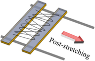
The so-called two-step collection is the integration of static collection and dynamic collection. To further improve the alignment degree of nanofibers, Conte et al. utilized the post-draw process to fabricate e-spun PVDF-co-hexafluoropropylene (PVDF-HFP) nanofibers (Conte et al., 2019), and Hsu et al. utilized the hot-stretching process to fabricate PS and PMMA nanofibers (Hsu et al., 2020) (method No. 18 in Table 1). After post-treatment, not only the alignment degree of e-spun nanofibers is improved, but also the nanofiber diameter is reduced. Another two-step process named contact-transfer printing was reported by Liu et al. and aligned PVDF nanofibers with the degree of order of ∼ 88.2 % were fabricated (Liu et al., 2012). Post-treatment could be used for both disordered nanofibers from conventional e-spinning and quasi-aligned nanofibers from any of the methods mentioned above. The process of these methods is to stretch the as-prepared disordered or quasi-aligned nanofibers in a specific direction under the action of external forces, so as to obtain a higher degree of aligned nanofiber array.
The large-scale preparation of aligned nanofibers is on the way to commercialization. The current commercialized machines and possible commercialized technologies are listed in Table 1. At present, the commercial machines that could realize the large-scale production of aligned nanofibers are mainly designed with reference to the rotating collector method. But the size of the machine is many times larger. Moreover, in order to improve spinning efficiency, commercial machines are generally equipped with multiple-point liquid supply device (e.g., multiple spinning needles), linear liquid supply device (metal chain), and planar liquid supply device (metal plate with vibration device). In addition, the centrifugal e-spinning apparatus also has commercial value. In contrast, the alignment achieved by self-assembly of nanofibers is of little commercial value.
3 Near-field electrospinning
The distance from the tip of the spinning needle to the collector can be divided into three kinds: Far-field (>10 cm), medium-field (1–10 cm), and near-field (<1 cm). From the viewpoint of the controllability (or precise deposition) of nanofibers, near-field e-spinning (NFES) is undoubtedly the most effective means.
NFES occurs in stage 2 and stage 3 in Fig. 1B, from the initial formation of polymer jet to the lower limit of polymer line. Because of the obvious decrease in spinning distance, the e-spinning voltage is greatly reduced. According to the electric field of conventional e-spinning, just 0.6–3 kV of electric voltage is enough to drive the fabrication of micro-/nanofibers in NFES. In addition, the lower voltage operating environment provides security for researchers. However, the NFES has insurmountable disadvantages. Because of the short spinning distance, the fibers cannot be further stretched and refined. So, the fiber diameters prepared by NFES are generally at the micron level. In the following, the development history and key nodes of NFES are briefly summarized.
3.1 NFES progress
NFES opens a new chapter for precise-deposition e-spinning, microfluidic weld, and micro-sensors. Especially in the past decade, both basic researches and applications have made tremendous development. Table 2 shows a summary of the development of NFES.
Year
Method or form
polymer
Spinning distance
Spinning voltage
Fiber diameter
Reference
2003
Scanned tip e-spinning deposition
PEO
0.5–2 cm
4–6 kV
100–1800 nm
(Kameoka et al., 2003)
2006
NFES
PEO
500 µm − 3 mm
1 kV
50–500 nm
(Sun et al., 2006)
2008
Atomic force microscope (AFM) assisted e-spinning
PEO
10–20 μm
8–12 V
150–430 nm
(Wu et al., 2008)
2008
Continuous NFES
PEO
500–1500 μm
< 1.5 kV
sub-100 nm
(Chang et al., 2008)
2009
High precision deposition e-spinning (HPDE)
PEO, Polyamide 6, PAN
0.5–10 mm
0.1–10 kV
hundreds of nm
(Hellmann et al., 2009)
2011
Coaxial NFES
Sugar-PCL
2 cm
5.5 kV
72–175 μm
(Zhou et al., 2011)
2011
Low-voltage NFES
PEO
1 mm
0.2–0.6 kV
< 20 nm
(Bisht et al., 2011)
2011
Direct writing melt e-spinning
PCL
30 mm
12 kV
∼ 21 μm
(Brown et al., 2011)
2015
Multi-nozzle NFES
PEO
5 mm
2 kV
—
(Wang et al., 2015)
Combined with the contents in Table 2, there is still some information to be stated. Kameoka et al. have utilized a Si tip instead of a nozzle to prepare aligned nanofibers with a small spinning distance and a low spinning voltage (Kameoka et al., 2003). Based on the mode of nozzle-free e-spinning and controllable deposition of e-spun nanofiber, NFES would be born. Until 2006, the NFES was presented by Sun et al. utilizing a tungsten electrode (25 µm in diameter) to fabricate nanofibers with the diameter of 50–500 nm just at a spinning distance of 500 µm to 3 mm (Sun et al., 2006). In 2008, Wu et al. used AFM to dip, adsorb and spin the polymer solution to prepare the single nanofiber at an ultra-low voltage (Wu et al., 2008), which could protect some precursor materials from high-voltage damage. In the same year, Chang et al. used a syringe needle (200 μm in outer diameter and 100 μm in inner diameter) to replace solid spinning nozzle to realize the continuous supply of spinning solution and prepared large-scale and complex patterned nanofibers (Chang et al., 2008). Hellmann et al. introduced the HPDE indicating an achievement of a linear deposition of nanofibers by a pre-designed pattern (Hellmann et al., 2009). In 2011, Zhou et al. achieved the combination of coaxial e-spinning and NFES (Zhou et al., 2011), so that hollow single polymer fibers and core–shell composite fibers can be prepared. In the same year, Bisht et al. used a low voltage NFES method to fabricate patterned polymeric nanofibers on 2D and 3D substrates (Bisht et al., 2011). And that opens the route towards 3D e-spinning. Brown et al. realized the accurate deposition of melt e-spun PCL fibers by direct writing spinning mode (Brown et al., 2011). Since then, a new chapter for 3D NFES, also called 3D printing e-spinning, has officially opened.
Some subsequent studies, including theory and application, are the supplement and expansion of NFES. For example, Wang et al. explored the double- and triple-nozzle NFES for high-precision deposition of aligned micro-/nanofibers (Wang et al., 2015). Throughout the whole history of NFES, the main influencing factors or breakthrough technologies are the change of spinning nozzles (single to multiple, solid to hollow), spinning mode (moving nozzle and moving collector) and corresponding moving speed, spinning distance, significant reduction of spinning voltage, spinning solution supply flow, etc. which are also the partial keys towards the later stages of ordered alignment of e-spun nanofibers.
4 3D printing electrospinning
4.1 Supporting theory of 3D printing e-spinning
4.1.1 Intervention e-spinning
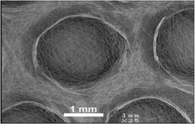
Intervention e-spinning mainly refers to the control of the spinning environment (e.g., temperature and humidity), change of spinning solution components, and input of additional charges. Yan et al. have fabricated honeycomb-patterned 3D nanofibrous structures, mainly relating to the control of concentrations and humidity (Yan et al., 2011). The 3D self-assembly appeared only in the condition of suitable temperature and humidity, such as self-assembly of PVA in the concentration of 5–7 % and the relative humidity < 45 %, or self-assembly of PEO in the concentration of 13–20 % and the relative humidity < 40 %. The higher humidity, lower temperature, and smaller spinning distance are not conducive to accelerating solvent evaporation. So, they belong to inappropriate conditions for 3D self-assembly. In the study of solution components, Li et al. fabricated huge fibrous stackings with a maximum height of 17 cm and a maximum bottom diameter of 20 cm (Li and Long, 2011). PVP/nitrate (Fe(NO3)3, Co(NO3)2, Ni(NO3)2 or their mixture with different mass ratio) solution and PS solution were successfully used to fabricate 3D nanofibrous structures. Doping changes the conductivity of pure polymer solution and makes it easy to form 3D nanofibrous structures. For example, PS solution doped with nitric acid, ferric sulfate, etc. has more advantages in the preparation of 3D structures compared with pure PS. The input of additional charges experiment (Sun et al., 2012) was carried. 15 wt% PS solution was used to fabricate 3D structures. When only aluminum foil was used as the collector, the 3D fibrous stacking was easy to form. But, when they put an insulation pad on the aluminum foil, a 2D membrane structure appeared. By introducing the negative charges generated by an electrostatic generator into the fibrous membrane, the 2D structures changed into 3D structures again. In other words, this method could realize the mutual transformation of 2D and 3D structures of nanofibers.
4.1.2 Melt e-spinning
The contribution of melt e-spinning to 3D printing e-spinning is to eliminate the process of solvent evaporation. In addition, a few polymer materials (e.g., PP and PE) do not have suitable organic solvents, so melt e-spinning is used to prepare ultrafine fibers. The key technology for melt e-spinning is the heating mode. Table 3 shows a summary of heating methods.
Heating method
Advantage
Disadvantage
Electrical heating
Simple operation, fast temperature elevation
Electrical interference
Laser heating
Independent heat source
High cost, precise operation, polarity polymer
Fire heating
Wide heat source, no additional heating electricity supply
Unstable and uneven heating
Microwave heating
Low cost, security, environment-friend
Polar polymer
Bath heating
Air
Simple technology and operation, low cost, safety
No precise control
Water
Stable heating temperature
Narrow heating range
Oil
Stable heating temperature
Higher heating temperature
Melt e-spinning shows great advantages in solventless e-spinning and rapid curing e-spinning (Zhang et al., 2016a, 2016b; He et al., 2016). For example, the UV-assisted method has been used in solventless e-spinning to fabricate nanofibers by Long’s group (He et al., 2016). 8 g of DR-U301 polyurethane acrylate (PUA) and 0.4 g of photoinitiator 1173 were mixed and heated by water bath (40–50 °C) into precursor solution. Under the conditions of UV irradiation and nitrogen atmosphere, the DR-U301 fibers were fabricated successfully. During the whole process, the total mass of precursor solution and e-spun fibers remained unchanged (without solvent evaporation).
4.1.3 Additive manufacturing
Additive manufacturing, also known as rapid prototyping or 3D printing technology, is a promising method for manufacturing 3D objects at present (Hwa et al., 2017). Here, Table 4 just shows some common techniques of 3D printing that may be applied in e-spinning.
Classification
Technique
Material
Brief introduction
Liquid
Stereolithography (SLA)
Photopolymer resin
Photopolymer resin is solidified into 3D objects under the action of laser irradiation
Semi-liquid
Fused deposition modeling (FDM)
Thermoplastic, eutectic system metal, edible material
Melted by heating and extruded from the printer nozzle, then solidified
Powder
Selective laser sintering (SLS)Selective laser melting
(SLM)Thermoplastic, metal powder, ceramic powder
Laser heating makes the powder materials melt to build 3D objects
Generally, the materials that can be e-spun into nanofibers cannot be solid. Therefore, FDM should be the first additive manufacturing technique that could be combined with e-spinning. Actually, the descriptions of FDM and NFES have been reported (Brown et al., 2011), and the UV curable e-spinning has also been mentioned above (He et al., 2016). However, the research on the combination of SLS/SLM and e-spinning has not been successfully implemented, meaning a huge space for exploration. It is boldly envisaged that the combination of SLA and e-spinning will become a rapid prototyping e-spinning. The combination of SLS or SLM and e-spinning will greatly promote the melt NFES.
4.2 Development of 3D printing e-spinning
In 2016, Zhang et al. presented a review on the translation from 2D NFES to 3D printing e-spinning (Zhang et al., 2016a, 2016b), which opened the door to 3D printing e-spinning. Following the researches of Brown et al. (Brown et al., 2011), Table 5 introduces the recent development of 3D printing e-spinning.
Year
Method
Material
Quantitative indicator
Reference
2017
Combinational processing of 3D printing and e-spinning
PLA/gelatin-forsterite
Prepare respectively: (aligned) PLA scaffolds via FDM, (disordered) gelatin-forsterite nanofibrous layers via e-spinning
(Naghieh et al., 2017)
2018
3D melt e-spinning printing
PCL
Complete the modeling for selecting process parameters in 3D melt e-spinning printing to control the fiber diameter
(Dayan et al., 2018)
2019
NFES-assisted lithography (NFEAL)
PEO/PS
Polymeric scaffolds with microgroove patterns
(Yang et al., 2019)
2020
Electrohydrodynamic jet 3D printing
PCL/PVP
Patterning synthetic 3D biopolymers structures with a high aspect ratio
(Li et al., 2020)
2021
3D printing NFES
PVDF
Aligned PVDF membrane with various geometric pore structures
(Liang et al., 2021)
2021
Tip electrode guiding e-spinning
PEO
Prepare 3D high-aspect-ratio (height/width = 25) structures of nanofibers
(Zheng et al., 2021)
A preliminary conclusion can be drawn from the information in Table 5. Currently, the technology used for ordered alignment of e-spun nanofibers and combined with e-spinning successfully is FDM. Additionally, other additive manufacturing technologies combined with e-spinning are also developing rapidly. How to combine additive manufacturing/printing technology with e-spinning is shown in Fig. 2. 3D printing e-spinning devices include a computer (Fig. 2A) which provides computer-aided design and generates executive files (Fig. 2B) and mechanical actuators (Fig. 2C) which work according to a preset program. In particular, the material processor can deal with the precursor solution by mixing, stirring, heating, and other processes. The control unit can control the flow rate of the polymer solution. Put the metal collector on the mobile platform, and connect the positive pole of DC HVPS to the printer nozzle (Fig. 2D). Then, 3D printing e-spinning can be carried out. For rapid prototyping of 3D fibrous structures, auxiliary technology can be introduced (Fig. 2E), such as UV curing.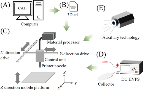
Schematic flow diagram of 3D printing e-spinning: (A) computer; (B) executive file; (C) mechanical actuator; (D) auxiliary e-spinning devices; (E) auxiliary technology.
3D printing e-spinning is still immature and in a period of rapid development. This technology hasn't been promoted on a large scale possibly due to two difficult problems: weak self-supporting ability and deposition uncertainty of micro-/nanofibers. Generally believed, the formation mechanism of 3D nanostructures is the result of interaction between mechanical support from nanofibers and electrostatic force. When the fibers fall from the spinning needle to the collector, solvent volatilization causes polymer separation. Then, polymer nanofibers are deposited on the collector. Under a high electric field, the fibers having reached the collector present polarization. Polarized fibers will produce an electrostatic repulsive (or attractive) force to the falling fibers. In the whole process, 3D nanostructures are fabricated gradually due to the support of the bottom fibers to the upper fibers, even though the supporting force is very small. Meanwhile, the repulsion from like electric charges plays a certain role in the space framework. It is certain that intervention e-spinning which has great advantages in preparing 3D nanofiber objects, melt e-spinning without solvent volatilization, and FDM which can prepare microfiber scaffolds would greatly promote 3D printing e-spinning.
5 Applications
The aligned e-spun nanofibers can enlarge a specific performance of nanofibers, such as mechanical, electrical, magnetic, and tensile properties. Here we will review the representative applications in recent five years. According to the dimension of aligned e-spun nanofibers, they are expressed from three aspects.
5.1 1D applications
The 1D ordered alignment of e-spun nanofibers mainly refers to the parallel aligned nanofiber structures, including the aligned nanofiber membranes that do not involve cross structures of nanofibers.
5.1.1 Field-effect transistors
Applications of e-spun nanofibers in the field-effect transistors (FETs) have been reported for a long time, for instance, aligned e-spun poly(3-hexylthiophene) nanofibers (Chen et al., 2011) and electrohydrodynamic direct-writing ZnO nanofibers (Wang et al., 2013) have been applied in FETs successfully. Another photoelectric material, titanium dioxide (TiO2), has also been widely used in the fabrication of various devices due to its excellent charge transport and transfer ability. Recently, Zhang et al. fabricated aligned TiO2 nanofibers by e-spinning and sintering method, then, as-spun TiO2 nanofibers were used to prepare top-gate FET devices (Zhang et al., 2019), as shown in Fig. 3A. In the process, a mixture of tetrabutyl titanate and PVP solution was e-spun at a voltage of 15 kV and a spinning distance of 20 cm, then, as-spun nanofibers were converted into TiO2 nanofibers by calcining at three different temperatures for 5 h in air. Research results showed that the prepared anatase–rutile TiO2 nanofibers (calcined at 550 °C) exhibited better transistor characteristics compared to the pure anatase (calcined at 450 °C) or rutile (calcined at 800 °C) TiO2 nanofibers, which should be due to the synergistic effect between both crystallites that could prevent the recombination of electrons and holes, and increase the separation of charge carriers. The turn-on voltage of prepared FET devices was ∼ 0.5 V. E-spun anatase–rutile TiO2 nanofibers could be an ideal building block in the production of FET devices. Due to the large specific surface area of e-spun nanofibers and the positive influence of aligned nanofibers on axial charge transport, the ordered alignment of e-spun nanofibers will shine in the processing of FET and photodetector, etc.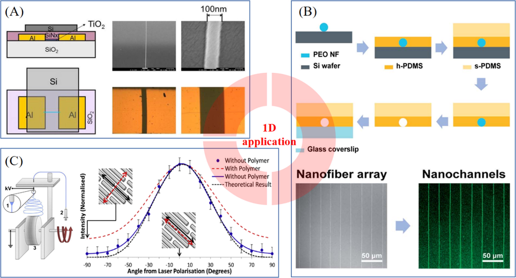
(A) FET-based nonvolatile memory device with a single TiO2 nanofiber (Zhang et al., 2019). (B) Preparation process of nanochannels and aligned PEO nanofibers prepared by NFES, fluorescence image of nanochannels (Park et al., 2018). (C) Preparation process of aligned PEO/CNTs nanofibers and intensities for the RBM of a 1.23 nm single-walled CNT peak as a function of angle between the laser polarisation direction and the axial direction of PEO/CNTs nanofibers (King et al., 2018). With permission from Elsevier.
5.1.2 Nanochannels
Nanochannels have attracted much attention because of their great advantages in regulating particle exchange and transport, preparing fluidic channels and electrode gaps, etc. The nanochannels could be sealed channels (Park et al., 2018) or open microgrooves (Yang et al., 2019). In 2018, Park et al. fabricated polydimethylsiloxane (PDMS) nanochannels via NFES (Park et al., 2018), as shown in Fig. 3B. First, PEO nanofibers were e-spun on a surface-modified Si wafer. Second, h-PDMS was used to cover the as-spun PEO nanofibers. Third, s-PDMS was poured and cured. Fourth, Si wafer was removed. Fifth, PEO nanofibers were dissolved. Sixth, nanochannels were bonded to other substrates. Through the above process, nanochannels with different widths of 70–368 nm, aspect ratios of 0.19–1.00 were prepared, indicating that different shapes and cross-sections of nanochannels could be realized by controlling the process of NFES to precisely deposit nanofibers. In 2019, utilizing the similar method, Yang et al. prepared microgrooved scaffolds used for C2C12 cell culture (Yang et al., 2019). In the process, they employed NFES to prepare aligned PEO nanofibers and then covered them with PS solution. After curing, they dissolved the PEO nanofibers with water to prepare patterned microgrooved scaffolds. The width of the microgroove prepared on PS substrate depends on the diameter of the e-spun PEO nanofibers. In the cell culture experiment, to facilitate cell adhesion, the PS substrate was coated with poly(l-lysine). Results showed that microgrooves could induce the directional growth of cells and elongate them, indicating e-spun aligned nanofibers have great application prospects in tissue engineering. Recently, Regmi et al. reported a preparation method of suspended graphene channel (Regmi et al., 2020), which could be used as a sensing element to detect NH3. In their study, PEO microfibers were direct-written on the synthesized graphene film and then the as-spun PEO microfibers would act as a mask for the graphene layer in the next oxygen plasma etching process. Meanwhile, PEO was also a p-type dopant for synthesized graphene layers. Experiments showed that bilayer graphene was a candidate for the preparation of suspended graphene, considering the mechanical stability and uniformity in etching, etc. It has been confirmed that the sensitivity of the sensor increases with the decrease of the channel width (sensitivity increased by 78 % along with the channel width from 15 μm to 5 μm), which gives us a vision when the channel width decreases to the nanometer level, the sensitivity will continue to improve.
Although there are many methods to prepare nanochannels, e-spinning is undoubtedly-one of the best choices from the perspective of high preparation efficiency, low cost, and convenient operation as well as adjustable space of nanochannel width. In particular, aligned nanofibers can be converted into other structures with controllable and regular geometry, which is of great significance to micromachining.
5.1.3 Guidance carrier
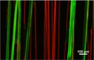
The ordered alignment of micro-/nanoparticles has always been a key research of nanotechnology, especially the long-range ordered alignment. Coincidentally, the ordered alignment of polymer nanofibers carrying micro-/nanoparticles by e-spinning brings a new idea to solve the above problems. Carbon nanotubes (CNTs) are often used as dopants in e-spun nanofibers, showing excellent mechanical, chemical, and electrical properties. Normally, the more aligned the arrangement of CNTs is, the more prominent their properties show. In the study of King et al., highly aligned CNTs arrays were prepared by e-spinning with a rotating collector (King et al., 2018), as shown in Fig. 3C (left), in which as-spun aligned PEO nanofibers acted as a guidance carrier. The improvement of the alignment degree of CNTs could be seen from Fig. 3C (right), in which, for perfectly aligned CNTs, the radial breathing mode (RBM) peak intensities are proportional to cos4θ, where θ is the angle between the laser polarisation direction and the axial direction of PEO/CNTs nanofibers. The reason for this phenomenon is that the nanofibers complete the radial extrusion and axial tension of the embedded CNTs in the ordered alignment. Further study found that the mechanical properties of the composite PEO/CNTs nanofibers were greatly improved compared with pure PEO samples. Especially, when the loading content of CNTs within PEO nanofibers is 3.9 % (0.7 %), the tensile strength (ductility) is increased by 320 % (315 %). Another application research in biological devices (Sakamoto et al., 2020) based on aligned CNTs embedded within aligned nanofibers was carried out by Sakamoto et al. Similarly, a rotating collector e-spinning was employed to embed CNTs into poly(ethylene-co-vinyl acetate) (PEVA) nanofibers. When PEVA was removed by combustion, it was found that CNTs were orderly arranged on the substrate by observing SEM images. The electrochemical performance analysis of electrodes shows that the aligned CNTs have stronger conductivity (lower charge transfer resistance) than the scattered CNTs. The sharp contrast is reflected in the bare electrode resistance of 40 Ω, the random CNTs-based electrode resistance of 20 Ω, and the aligned CNTs-based electrode resistance of 8 Ω. Sharafkhani et al. also proved that the orderly incorporation of CNTs in PVDF nanofibers could effectively increase their piezoelectric properties (Sharafkhani and Kokabi, 2021), and therefore could be applied to piezoelectric actuators. Currently, the ultimate solution to the problem of improving or enlarging the performance based on aligned CNTs arrays is to increase the loading rate and alignment degree of CNTs.
As the carrier of effective components, e-spun aligned nanofibers also show great application value in drug delivery. Eslamian et al. conducted a special study on the effects of aligned and disordered nanofibers loaded with drugs on drug sustained release (Eslamian et al., 2019). In the process, they utilized e-spinning to obtain aligned dexamethasone (DEX)-loaded poly(lactic-co-glycolic acid) (PLGA) nanofibers on the metallic rotating wheel collector. The data analysis of sustained release (calculated by counting the dissolution of DEX-loaded PLGA fibers in chloroform) showed that, at some time points, the drug release rate of aligned fiber carrier was about 10 % lower than that of disordered fiber carrier. The reason is that the aligned fibers can lock the drug components better on the surface and inside of the nanofibers in the preparation process, while the disordered fibers have a greater burst release of drug. Therefore, aligned nanofibers as drug carriers have more advantages in controlled release and sustained release.
Although 1D nanostructures can also be prepared by other methods, e-spinning is undoubtedly the most ideal technology in terms of the length of products, the simplification of preparation process, the low cost, and the controllability of parameters. In addition to the characteristics of large specific surface area and high porosity of nanofibers, etc., the ordered alignment of nanofibers has great advantages in charge transport rate and orientation control, which directly determines the greater application prospect (Choi et al., 2021). The comparative study of Guo et al. about aligned nanofibers and disordered nanofibers in lasing action proved this view (Guo et al., 2018). Researches revealed that optical amplification could be observed in both aligned and disordered nanofibers of 4-(dicyanomethylene)-2-tert-butyl-6(1,1,7,7-tetramethyljulolidyl-9-enyl)-4H-pyran (DCJTB): PVP, but aligned nanofibers exhibited smaller threshold and stronger polarization characteristics.
5.2 2D applications
The 2D ordered alignment of e-spun nanofibers mainly refers to the nanofiber membrane structures with specific geometric holes and the nanofiber arrays composed of ordered and crossed fibers. Herein, three innovative applications based on the 2D ordered alignment of e-spun nanofibers are reviewed.
5.2.1 Platform for gas detection
The fabrication of patterned polymer nanofibers by NFES has been realized. However, the preparation of patterned metal oxide nanofibers with precisely controlled deposition still faces great challenges. In 2019, for the first time, Lim et al. completed the preparation of patterned metal oxide nanofibers by NFES (Lim et al., 2019). In2O3, Co3O4, and NiO nanofibers with grid, diamond, and hexagon patterns (from precursor patterns by heat treatment at 600 °C for 5 h) were fabricated, in which PVP acted as the basic material. In addition, they also reported the advantages of as-prepared nanostructures as a novel gas sensing platform, as shown in Fig. 4A. In particular, they selected In2O3 nanofibers with grid patterns (In2O3-P) as the detection platform to monitor trimethylamine (TMA), while a sensor based on thin-film In2O3 (In2O3-F) was also prepared for comparative study. The results indicated that within the preset concentration range of TMA at 350 °C, the sensitivity of the nanofiber-based sensor was significantly higher than that of the thin film-based sensor. Meanwhile, the detection for other gases was also implemented at 350 °C, indicating the In2O3-P sensor had great selectivity and discrimination to TMA. It also should be noted that the responses of In2O3-P sensor were the highest, compared with those of nanostructure gas sensors reported before. What can better reflect the practical application value is that the In2O3-P sensor has excellent stability (>30 days) (Fig. 4A). The patterned metal oxide nanofibers as advanced functional materials would play a great role in designing nanodevices, not limited to gas sensors, due to the shorter electron transport path, resulting in faster response time.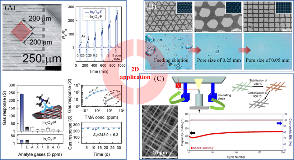
(A) application of In2O3-P sensor, Ra: sensor resistance in air, Rg: sensor resistance in gas, T: TMA, E: ethanol, A: ammonia, X: p-xylene, t: toluene, B: benzene, e: ethylene, and C: CO (Lim et al., 2019). (B) Different patterned PVDF nanofiber films with triangle, hexagon, square pore shape, and filtration effect of prepared membranes (Liang et al., 2021). (C) Preparation process of cross-aligned carbon nanofibers via an insulating block e-spinning technique and cyclability tests at 3000 mA g−1 (Cheong et al., 2021). With permission from Royal Society of Chemistry and Elsevier.
5.2.2 Filter
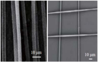
E-spun nanofiber membrane is widely used in the field of filtration because of its small pore size and high porosity. In 2021, Liang et al. fabricated PVDF nanofiber membranes with different pore shapes (e.g., triangle, hexagon, square, etc.) by 3D printing NFES used for the filtration of solid microparticles (Liang et al., 2021), as shown in Fig. 4B. PVDF/SiO2 solution as the precursor material was prepared by dissolving PVDF in N, N-dimethylacetamide (DMAc) and acetone (4:1 in mass) to form a uniform solution of 14 wt%, and then adding SiO2 particles with a particle size of 40 nm into the as-prepared solution. According to preset parameters (3.5 kV in spinning voltage, 5 mm in spinning distance, 0.25 mL h−1 in solution flow rate), patterned nanofiber membranes with different pore sizes (0.05 mm, 0.10 mm, 0.15 mm, 0.20 mm, and 0.25 mm) were prepared. It should be noted that when the preset pore size was<0.05 mm, the fibers appeared stacking phenomenon, which led to the small porosity of the fiber membranes. The results of filtration experiments for a feeding solution containing 50 μm microparticles showed that the filtration effect increased with the decrease of pore size of fiber membranes (Fig. 4B), and the particle rejection ratio could reach 96.7 % by the fiber membranes with 0.1 mm pore size. In addition, it was also found that the water flux could be significantly improved by adjusting the length to width ratio of the preset pore size of the fiber membranes. These membrane structures with adjustable pore size and shape have provided a scheme for precision separation in the future.
5.2.3 Electrode materials
For electrochemical cells, some novel electrodes which can act as both current collector and active material are attracting great interest. In 2021, Cheong et al. (Cheong et al., 2021) employed an insulating block e-spinning technique (Hwang et al., 2016) to prepare cross-aligned carbon nanofibers used for the storage of lithium electrode materials. In the process, the diameter of e-spun PAN nanofibers could be reduced by 30 %-40 % after carbonization. Furthermore, a series of electrochemical performance tests were carried out, and the results demonstrated that the capability based on cross-aligned carbon nanofibers was higher than that of disordered carbon nanofibers under any current density (100, 200, 500, and 1000 mA g−1) tests, indicating the enhanced electrochemical performance from the ordered alignment of e-spun carbon nanofibers. Especially at a high current density of 3000 mA g−1, the reversible capacity was as high as 259.4 mAh g−1 along with the coulombic efficiency of 99.9 % (Fig. 4C). Additionally, by the impedance tests and postmortem analysis, it was also found that the surface of individual cross-aligned carbon nanofibers had more uniform solid electrolyte interphase layers compared with disordered carbon nanofibers after cycling. That is one of the reasons for less cell resistance and high reversible capacity of cross-aligned carbon nanofibers. Inspired by the efficient storage of lithium by cross-aligned carbon nanofibers, it can be boldly predicted that this ordered alignment of e-spun nanofibers could also be applied to other existing or developing electrode materials, which will greatly promote the development of chemical battery industry.
For the applications of 2D ordered alignment of e-spun nanofibers, the cross-aligned nanofiber membranes with regular geometric holes are the most widely used, such as the preparation of flexible transparent electrodes (Yousefi et al., 2019), etc. If you want to achieve the precise deposition of nanofibers, you can employ NFES. If you want to achieve large-scale preparation, you can utilize traditional e-spinning to collect 1D aligned (parallel) nanofibers, and then rotate the collector 90 degrees for secondary collection.
5.3 3D applications
The 3D ordered alignment of e-spun nanofibers is developed on the foundation of 2D alignment, and its typical feature is the large depth to width ratio of nanostructures. Most of the related applications are concentrated in the field of bioengineering, such as cell culture, tissue regeneration, etc. Of course, some other application fields are also involved. Three representative applications are as follows.
5.3.1 Bioengineering
Cell culture is an important part of bioengineering, and an ideal scaffold is the foundation of 3D structured cell culture. In 2018, He et al. employed NFES to fabricate 3D aligned PCL and hydroxyapatite (HAp) scaffolds with large pore sizes (>100 μm) used for cell culture (He et al., 2018). During the process of mouse pre-osteoblast cell culture in vitro, it was found that the cells could proliferate and differentiate in the as-prepared non-toxic and degradable scaffolds. Recently, Li et al. also successfully fabricated PCL/PVP composite scaffolds with high aspect ratios (∼30) by 3D printing e-spinning (Li et al., 2020). In vitro cell culture experiments confirmed that the cells could proliferate and differentiate in the biocompatible 3D scaffolds. Fig. 5A shows the change of cell density, the comparison of viability, and the observation of cell morphology with time. As an important application of cell culture, tissue regeneration has made great progress. For instance, Pozzobon et al. fabricated a biodegradable nerve conduit composed of aligned PLGA-gelatin nanofibers used for nerve regeneration (Pozzobon et al., 2021). The biggest advantage of the ordered alignment of e-spun nanofibers in cell culture is the adjustability and controllability of scaffold structure and pore sizes.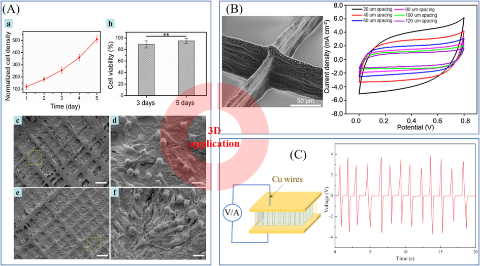
(A) Cell culture on scaffolds: (a) change of cell density, (b) the comparison of viability, (c-f) the observation of cell morphology with time, where (c-d) for 3 days and (e-f) for 5 days (Li et al., 2020). (B) SEM images of C-Ni 3D microstructures and current density-potential curves of C-Ni electrodes with different fiber spacings (Zhang et al., 2021). (C) Diagram of vertically-aligned BCTZY nanofibers-based nanogenerator and output voltage with a finger tap test (Wu et al., 2019). With permission from Elsevier.
E-spun nanofibers could be used not only for cell culture but also for cell capture, especially for cancer cell capture. In the study of Zhao et al., the capability of hyaluronic acid-immobilized aligned and disordered PLA nanofibers to capture CD44 receptor-overexpressing cancer cells was compared (Zhao et al., 2019), demonstrating that the cell capture efficiency of aligned nanofibers is higher than that of disordered nanofibers. In addition to the advantages mentioned above, the uniformity of the structure is also one of the reasons.
5.3.2 Supercapacitor
How to improve the areal specific capacitance and mass specific capacitance of electrode materials has always been the key problem in the preparation of supercapacitors. Different from the traditional preparation process of spin-coated electrodes, Zhang et al. prepared an electrode of carbon/nickel composite architecture with regular and well-organized networks by employing an electrohydrodynamic 3D printing method (similar to NFES) and applied this electrode to supercapacitors (Zhang et al., 2021) (Fig. 5B). In the process, PAN/Ni(NO3)2 fibers were firstly e-spun (printed) into 3D networks, then carbonized. At last, the C-Ni electrodes were successfully prepared. More importantly, the porosity and electrical conductivity of composite electrodes can be adjusted by setting different printed fiber spacing. The results indicated that with the increase of fiber spacing (from 20 μm to 120 μm), the porosity of electrodes increased (from 13.2 ± 4.6 % to 73.6 ± 6.9 %), but the conductivity decreased (from 0.062 ± 0.006 S cm−2 to 0.01 ± 0.004 S cm−2), as well as the areal specific capacitance gradually decreased while the mass specific capacitance increased first with the fiber spacing in the range of 20 to 60 μm and then decreased with the fiber spacing in the range of 60 to 120 μm. Under the optimal conditions, the as-prepared C-Ni electrodes have achieved a 2.3 times higher areal specific capacitance and 1.7 times higher mass specific capacitance compared with the spin-coated sample.
The advantages of composite electrodes aided by the ordered alignment of e-spun micro-/nanofibers are low preparation cost (compared with photolithography process, photosensitive materials, etc.) and facile controllability of nanostructure (e.g., fiber diameter, fiber gap, etc.), implying more important information that the size of prepared structures can be as low as micro-/nanoscale level, which directly determines the porosity and specific surface area of the structures, and then affects the high capacitance of the materials. These progresses could provide advanced strategies for the research and development of high-performance energy storage devices.
5.3.3 Nanogenerator
With the concept of replacing old growth drivers with new ones being put forward, the development of new energy and the design of self-powered systems are developing unprecedentedly. In 2012, a triboelectric nanogenerator (Fan et al., 2012) was reported by Fan et al. Since then, nanogenerators based on various electrification theories have been widely studied. Among them, a piezoelectric nanogenerator base on vertically-aligned lead-free (Ba0.85Ca0.15)(Ti0.9Zr0.1)O3-0.2 mol%Y (BCTZY) nanofibers (Wu et al., 2019) was introduced by Wu et al. (Fig. 5C). PVP-BCTZY nanofibers were firstly collected by a rotating drum via e-spinning, and then calcined at 450 °C for 1 h and sintered at 700 °C for 2 h, lastly cut and turned 90 degrees, achieving the transition to vertically-aligned BCTZY nanofibers. The tests of vertically-aligned BCTZY nanofibers-based nanogenerator showed that by adding Y element, the continuity, flexibility, alignment, dielectric properties, ferroelectric properties, and piezoelectric properties of composite nanofibers were greatly improved compared with those of the BCTZ nanofibers. Furthermore, this vertically aligned nanostructure itself has many advantages over the planar aligned nanofiber structure and membrane structure, lying in that the vertically aligned nanofibers could accumulate more charges and be more compliant to mechanical stress (Wu et al., 2019). Therefore, the as-prepared vertically-aligned BCTZY nanofibers-based nanogenerator shows excellent tiny energy harvesting and power output abilities, and even with a finger tap, there is an electrical output of voltage of 3 V and current of 85nA. The advantages of this structure were also confirmed by Krishnamoorthy et al. in the study of vertically aligned anatase TiO2 nanowires used in the preparation of dye-sensitized solar cells (Krishnamoorthy et al., 2011).
6 Summary and outlook
Ordered alignment of e-spun nanofibers, as a part of intelligent control manufacturing, is bound to play tremendous roles in fine chemical industry. In this review, various e-spinning methods of ordered alignment are summarized and compared, aiming to clear a path of development: From quasi guidance to precision guidance of e-spun nanofibers. In particular, the development and significance of NFES and 3D printing e-spinning in the ordered alignment of e-spun nanofibers are highlighted.
It could be concluded that the ordered alignment of e-spun nanofibers should mainly rely on the following methods: (1) Coaxial e-spinning, depending on the combination of matrix and reinforcement, by inner or outer support of materials, can realize space construction. Furthermore, if the outer layer substance of coaxial e-spinning is airflow, the coaxial e-spinning is deformed into air-assisted e-spinning. (2) Melt e-spinning, lying in rapid solidification, by reducing the solvent evaporation process, can improve the forming efficiency. (3) Modified polymer e-spinning, based on doping or construction of welding/melting point structure, has the most extensive operation space. (4) Special environment control e-spinning, by means of the control of pressure, temperature, or high-energy environment can achieve differentiated operation for a certain material. (5) Physical control e-spinning, drawing support from the reverse lifting force, such as magnetic polymer in a magnetic field, by the combination with modified polymer e-spinning, is regarded as the representative of external interference operation.
The fundamental reason for the great development of aligned nanofibers-based applications is that aligned nanofibers can amplify a certain characteristic. In this review, we introduce the applications of e-spun nanofibers in field-effect transistor, nanochannel, guidance carrier, platform for gas detection, filter, electrode materials storage, bioengineering, supercapacitor, and nanogenerator from 1D, 2D and 3D structures with aligned e-spun nanofibers. The ordered alignment of nanofibers must attract more and more attention in the future because of the adjustability and controllability of their microstructures. Moreover, 3D printing e-spinning is likely to become the next research hotspot.
Acknowledgments
This work was supported by the National Natural Science Foundation of China (51973100), the State Key Laboratory of Bio-Fibers & Eco-Textiles, Qingdao University (RZ2000003334 and ZDKT202108), the National Key Research Development Project (2019YFC0121402), and Shandong Province Introduction of Top Talents (Team) “One Thing, One Discussion” (DC1900013728).
References
- Alignment and optimization of nylon 6 nanofibers by electrospinning. J. Appl. Polym. Sci.. 2008;107:3023-3032.
- [Google Scholar]
- Controlled continuous patterning of polymeric nanofibers on three-dimensional substrates using low-voltage near-field electrospinning. Nano Lett.. 2011;11:1831-1837.
- [Google Scholar]
- Continuous near-field electrospinning for large area deposition of orderly nanofiber patterns. Appl. Phys. Lett.. 2008;93:123111
- [Google Scholar]
- Manipulation on the morphology and electrical properties of aligned electrospun nanofibers of poly(3-hexylthiophene) for field-effect transistor applications. Macromolecules. 2011;44:2883-2892.
- [Google Scholar]
- Use of electrospinning and dynamic air focusing to create three-dimensional cell culture scaffolds in microfluidic devices. Analyst. 2016;141:5311-5320.
- [Google Scholar]
- Cross-aligned carbon nanofibrous network for efficient and outstanding high-rate Li storage capability. Electrochim. Acta. 2021;387:138457
- [Google Scholar]
- Aligned cellulose nanofiber composite made with electrospinning of cellulose nanofiber - Polyvinyl alcohol and its vibration energy harvesting. Compos. Sci. Technol.. 2021;209:108795
- [Google Scholar]
- Effects of post-draw processing on the structure and functional properties of electrospun PVDF-HFP nanofibers. Polymer. 2019;171:192-200.
- [Google Scholar]
- Modeling 3D melt electrospinning writing by response surface methodology. Mater. Design. 2018;148:87-95.
- [Google Scholar]
- Electrospinning of highly aligned fibers for drug delivery applications. J. Mater. Chem. B. 2019;7:224-232.
- [Google Scholar]
- Formhals, A., 1934. Process and apparatus for preparing artificial threads. US Patent 1975504.
- Direct fabrication of twisted nanofibers by electrospinning. Appl. Phys. Lett.. 2007;90:263902
- [Google Scholar]
- Lasing action from dye doped polymeric nanofibers: A comparison study of well aligned with randomly oriented nanofibers. Org. Electron.. 2018;63:52-57.
- [Google Scholar]
- A novel layer-structured scaffold with large pore sizes suitable for 3D cell culture prepared by near-field electrospinning. Mater. Sci. Eng. C. 2018;86:18-27.
- [Google Scholar]
- Solvent-free electrospinning of UV curable polymer microfibers. RSC Adv.. 2016;6:29423-29427.
- [Google Scholar]
- High precision deposition electrospinning of nanofibers and nanofiber nonwovens. Polymer. 2009;50:1197-1205.
- [Google Scholar]
- Alignment-improved and diameter-reduced electrospun polymer fibers via the hot-stretching process. Macromol. Mater. Eng.. 2020;305:1900637.
- [Google Scholar]
- A review on polymer nanofibers by electrospinning and their applications in nanocomposites. Compos. Sci. Technol.. 2003;63:2223-2253.
- [Google Scholar]
- Recent advances in 3D printing of porous ceramics: A review. Curr. Opin. Solid. St. M.. 2017;21:323-347.
- [Google Scholar]
- Fabrication of aligned nanofibers by electric-field-controlled electrospinning: insulating-block method. Nanotechnology. 2016;27:435301
- [Google Scholar]
- A scanning tip electrospinning source for deposition of oriented nanofibres. Nanotechnology. 2003;14:1124-1129.
- [Google Scholar]
- Continuous electrospinning of aligned polymer nanofibers onto a wire drum collector. Nano Lett.. 2004;4:2215-2218.
- [Google Scholar]
- Probing of polymer to carbon nanotube surface interactions within highly aligned electrospun nanofibers for advanced composites. Carbon. 2018;138:207-214.
- [Google Scholar]
- A first report on the fabrication of vertically aligned anatase TiO2 nanowires by electrospinning: Preferred architecture for nanostructured solar cells. Energy Environ. Sci.. 2011;4:2807-2812.
- [Google Scholar]
- Fabrication of continuous microfibers containing magnetic nanoparticles by a facile magneto-mechanical drawing. Nanoscale Res. Lett.. 2016;11:426.
- [Google Scholar]
- Fabrication of self-assembled three-dimensional fibrous stackings by electrospinning. Mater. Sci. Forum. 2011;688:95-101.
- [Google Scholar]
- Fabrication of one dimensional superfine polymer fibers by double-spinning. J. Mater. Chem.. 2011;21:13159-13162.
- [Google Scholar]
- Highly aligned PAN nanofiber bundles prepared via a novel Venturi tube high-speed airflow drafting (VAD) method. Mater. Lett.. 2021;302:130383
- [Google Scholar]
- Electrospinning of polymeric and ceramic nanofibers as uniaxially aligned arrays. Nano Lett.. 2003;3:1167-1171.
- [Google Scholar]
- Electrohydrodynamic jet 3D printing of PCL/PVP composite scaffold for cell culture. Talanta. 2020;211:120750
- [Google Scholar]
- PVDF fiber membrane with ordered porous structure via 3D printing near field electrospinning. J. Membrane Sci.. 2021;618:118709
- [Google Scholar]
- Metal oxide patterns of one-dimensional nanofibers: on-demand, direct-write fabrication, and application as a novel platform for gas detection. J. Mater. Chem. A. 2019;7:24919-24928.
- [Google Scholar]
- Assembly of well-aligned electrospun nanofibers via contact-transfer printing. Adv. Mater. Res.. 2012;562–564:277-280.
- [Google Scholar]
- The use of air-flow impedance to control fiber deposition patterns during electrospinning. Biomaterials. 2012;33:771-779.
- [Google Scholar]
- Combinational processing of 3D printing and electrospinning of hierarchical poly(lactic acid)/gelatin-forsterite scaffolds as a biocomposite: Mechanical and biological assessment. Mater. Design. 2017;133:128-135.
- [Google Scholar]
- Non-lithographic nanofluidic channels with precisely controlled circular cross sections. RSC Adv.. 2018;8:19651-19658.
- [Google Scholar]
- Development of a conduit of PLGA-gelatin aligned nanofibers produced by electrospinning for peripheral nerve regeneration. Chem.-Biol. Interact.. 2021;348:109621
- [Google Scholar]
- Suspended graphene sensor with controllable width and electrical tunability via direct-write functional fibers. J. Manuf. Process.. 2020;58:458-465.
- [Google Scholar]
- Nanometre diameter fibres of polymer, produced by electrospinning. Nanotechnology. 1996;7:216-223.
- [Google Scholar]
- Nanofiber-guided orientation of electrospun carbon nanotubes and fabrication of aligned CNT electrodes for biodevice applications. Mater. Chem. Phys.. 2020;245:122745
- [Google Scholar]
- High performance flexible actuator: PVDF nanofibers incorporated with axially aligned carbon nanotubes. Compos. Part B-Eng.. 2021;222:109060
- [Google Scholar]
- Self-assembly of a three-dimensional fibrous polymer sponge by electrospinning. Nanoscale. 2012;4:2134-2137.
- [Google Scholar]
- A dynamic liquid support system for continuous electrospun yarn fabrication. Polymer. 2007;48:3400-3405.
- [Google Scholar]
- Electrospun fibre bundle made of aligned nanofibres over two fixed points. Nanotechnology. 2005;16:1878-1884.
- [Google Scholar]
- Electrostatic field-assisted alignment of electrospun nanofibres. Nanotechnology. 2001;12:384-390.
- [Google Scholar]
- Increasing electrospun scaffold pore size with tailored collectors for improved cell penetration. Acta Biomater.. 2011;7:2544-2557.
- [Google Scholar]
- Multi-compartment centrifugal electrospinning based composite fibers. Chem. Eng. J.. 2017;330:541-549.
- [Google Scholar]
- Study of deposition characteristics of multi-nozzle near-field electrospinning in electric field crossover interference conditions. AIP Adv.. 2015;5:041302
- [Google Scholar]
- Electrohydrodynamic direct-writing ZnO nanofibers for device applications. Mater. Lett.. 2013;109:58-61.
- [Google Scholar]
- Vertically-aligned lead-free BCTZY nanofibers with enhanced electrical properties for flexible piezoelectric nanogenerators. Appl. Surf. Sci.. 2019;469:283-291.
- [Google Scholar]
- Self-assembly of electrospun polymer nanofibers: A general phenomenon generating honeycomb-patterned nanofibrous structures. Langmuir. 2011;27:4285-4289.
- [Google Scholar]
- Fabrication of aligned fibrous arrays by magnetic electrospinning. Adv. Mater.. 2007;19:3702-3706.
- [Google Scholar]
- Fabrication of microgrooved scaffolds using near-field electrospinning-assisted lithography (NFEAL) J. Ind. Eng. Chem.. 2019;80:471-478.
- [Google Scholar]
- Uniaxially aligned microwire networks for flexible transparent electrodes using a novel electrospinning set-up. Sol. Energy. 2019;188:1111-1117.
- [Google Scholar]
- Micro/nanoscale electrohydrodynamic printing: from 2D to 3D. Nanoscale. 2016;8:15376-15388.
- [Google Scholar]
- Electrohydrodynamic 3D printing of orderly carbon/nickel composite network as supercapacitor electrodes. J. Mater. Sci. Technol.. 2021;82:135-143.
- [Google Scholar]
- Electrospinning of ultrafine conducting polymer composite nanofibers with diameter less than 70 nm as high sensitive gas sensor. Materials. 2018;11:1744.
- [Google Scholar]
- Facile fabrication and transistor properties of mixed crystalline TiO2 nanofibers FET devices. Mater. Lett.. 2019;246:99-102.
- [Google Scholar]
- Capturing cancer cells using hyaluronic acid-immobilized electrospun random or aligned PLA nanofibers. Colloid. Surface. A. 2019;583:123978
- [Google Scholar]
- Nanofibrous patterns by direct electrospinning of nanofibers onto topographically structured non-conductive substrates. Nanoscale. 2013;5:4993-5000.
- [Google Scholar]
- High-aspect-ratio three-dimensional electrospinning via a tip guiding electrode. Mater. Design. 2021;198:109304
- [Google Scholar]
- Electrospun aligned fibrous arrays and twisted ropes: Fabrication, mechanical and electrical properties, and application in strain sensors. Nanoscale Res. Lett.. 2015;10:475.
- [Google Scholar]
- Jet deposition in near-field electrospinning of patterned polycaprolactone and sugar-polycaprolactone core-shell fibres. Polymer. 2011;52:3603-3610.
- [Google Scholar]


