

Translate this page into:
Functionalized halloysite template-assisted polyaniline synthesis high-efficiency iron/nitrogen-doped carbon nanotubes towards nonprecious ORR catalysts
⁎Corresponding author. yaochao420@163.com (Chao Yao)
-
Received: ,
Accepted: ,
This article was originally published by Elsevier and was migrated to Scientific Scholar after the change of Publisher.
Peer review under responsibility of King Saud University.
Abstract
The iron-functionalized halloysite nanotudes is synthesized as a tubular template from an iron-nitrogen co-doped carbon nanocatalyst derived from the polyaniline pyrolysis of Oxygen reduction reaction (ORR). The use of iron-doped sites exposes the surface of the material to more graphite defects, effectively increasing the specific surface area of the carbon nanotubes and optimizing the density of the nitrogen-containing active sites. We have found that this iron-nitrogen co-doped carbon nanotube exhibits a superior ORR performance with a half-wave potential of 0.77 V in the 0.1 mol L−1 KOH aqueous solution. The electrochemical stability test was carried out at 1600 rpm. The half-wave potential showed only a degradation of 8 mV, which was better than the commercial 20% Pt/C (18 mV). This study developed an economical method for the direct synthesis of iron-nitrogen co-doped carbon nanotubes using a hard template.
Keywords
Iron/nitrogen-doped
Halloysite
Template-assisted
Polyaniline
Oxygen reduction reaction

1 Introduction
The energy crisis and environmental pollution are getting worse. Fuel cells have become the most popular and ideal new energy source because of their cleanliness, efficiency and sustainability. The oxygen reduction reaction process of the fuel cell cathode is so slow that a large amount of catalyst is required to accelerate the reaction, which greatly affects the working efficiency of the fuel cell (Bao et al., 2013). Precious metal ORR catalysts can improve their catalytic performance and enhance methanol tolerance toward ORR in an alkaline solution by optimizing metal nanostructures (Xue et al., 2018; Zhao et al., 2018; Xu et al., 2016). At present, most of the cathode oxygen reduction catalysts used on the market is Pt/C catalysts. Due to the high price and instability of Pt / C catalysts, the large-scale use of fuel cells is limited. Therefore, it is urgent to develop a low-cost, high-efficiency oxygen reduction catalyst to replace Pt/C.
Recently, studies have shown that metal-free nitrogen-doped carbon nanomaterials have potential catalytic oxygen reduction properties (Kou et al., 2018). Jiang et al. (2017) prepared a stretchable double-walled nitrogen-doped carbon nanofiber through a Petri-dish wetspinning method, which showed 100% strain stability in the electrode, but could not achieve high catalytic performance similar to Pt/C. Single-atom doped catalytic materials have been difficult to meet practical needs. (Guo et al., 2016; Xu et al., 2017; Higgins et al., 2014) More and more scientists are beginning to study alkaline fuel cells, (Osmieri et al., 2018; Pan et al., 2018) transition metal oxide-based catalysts (Gao et al., 2017; Kim et al., 2016; Ratso et al., 2017) and transition metal/N/C catalysts (Ai et al., 2017; Cai et al., 2017; Papiya et al., 2017; Ma et al., 2018; Lin et al., 2018; Jia et al., 2016; Lei et al., 2018). Kumar et al. (2016) prepared a ternary composite with acicular Fe3O4 on the surface by mechanical mixing. It has a higher specific surface area and still maintains superior ORR performance under high temperature conditions. However, the properties of transition metal oxides are closely related to oxygen vacancies (Haemori et al., 2009), which seriously affect the long-term stability of the catalyst. Ai et al. (2017) obtained a high performance Co-N-C nanocatalyst by heat treating a metal organic precursor. However, metal macrocyclic compounds are easily decomposed by hydrolysis and intermediates, resulting in extremely poor electrode stability. Although heat treatment can improve its stability, it still has a gap with the Pt/C catalyst. Qiao et al. (2017) successfully prepared a three-dimensional network of Fe-N-C nanocatalysts adsorbing iron ions in an aniline precursor. This material is superior in catalytic activity and stability. Carbon-based nanomaterials not only provide good stability of the catalyst, but also the metal-nitrogen interaction greatly enhances the ORR activity of the catalyst. Compared with metal-based nanomaterials, the Fe-N-C catalyst preparation method is simpler, the raw materials are more economical, and the stability is better. The catalyst performance is superior to that of the metal-free nanocatalyst. Therefore, loading Fe-N-C active species into the CNTs structure has the potential to be an effective method for preparing high performance ORR catalysts.
Due to the unique properties of Fe3+ in the synthesis process, a new method for synthesizing iron-nitrogen co-doped carbon nanotubes has been developed in this paper. Halloysite nanotubes are a natural and safe nanomaterial with low prices and abundant reserves Lvov et al. (2016). The halloysites of different geological deposits have different microstructures Cavallaro et al. (2018). Makaremi et al. (2017) found that shorter nanotubes are better able to encapsulate salicylic acid into their lumen than patchy structure and longer tubes of patch halloysite nanotubes. In the pH range of 2–8, halloysite has a positively charged inner cavity and a negatively charged outer surface because the outer surface is composed of Si-O-Si groups and the inner surface is composed of Al-OH groups Cavallaro et al. (2016). Recently, the surface modification of the halloysite cavity by an anionic surfactant has been studied, and an inorganic micelle capable of dissolving hydrophobic contaminants has been prepared Cavallaro et al. (2018). There have been many reports on the application of halloysite in metal nanomaterials (Massaro et al., 2017; Samahe et al., 2018), polymers (Cavallaro et al., 2018; Vasiliev et al., 2017; Ye et al., 2017), heavy metal ions (Vinokurov et al., 2017) and metal organic framework materials (Liang et al., 2019). Its high specific surface area provides a rich active site for the adsorption of iron ions (Joussein et al., 2005). The tubular structure of halloysite can be a template for the core-shell metal support for mesoporous catalysts (Lazzara et al., 2018). The unique hollow tubular structure of HNTs makes its inner and outer surfaces rich in hydroxyl groups, which can induce the growth of polyaniline in situ (Li et al., 2013; Liu et al., 2019). Polyaniline has been shown to be rich in nitrogen and carbon sources. It has good electrical conductivity itself. When Fe3+ ions are introduced into the polyaniline synthesis system, iron ions can be combined with the imine N and amine N atom of the polyaniline chain to form PANI-iron coordination polymer (Izumi et al., 2006; Wang et al., 2014). Polyaniline synergizes with halloysite to promote the doping of iron ions. The iron-functionalized halloysite nanotubes/polyaniline (Fe-HNTs/PANI) pyrolyzes and etches away the mineral template, and finally successfully prepares a catalyst material with excellent catalytic oxygen reduction activity and stability. The iron and nitrogen doping content can be effectively increased by adjusting the pyrolysis temperature. Compared with the traditional method, this strategy of using ion adsorption to achieve transition metal doping provides a new idea for the development of non-precious metal oxygen reduction catalysts.
2 Experimental
2.1 Materials and methods
Halloysite (Al2Si2O5(OH)4·2H2O) was purchased from Jiangsu NDZ Technology Group Co., Ltd. The 5 wt% nafion solution used to prepare the electrode was purchased from Sigma-Aldrich. The aniline needs to be distilled under reduced pressure before use to ensure its purity. All reagents (National Medicine Chemical Reagent Co., Ltd. China) were of analytical grade and could be used without further purification. The water used in this study was deionized by milli-Q Plus system (Millipore, France), having 18.2 MΩ electrical resistivity.
First, 2.7 g of FeCl3·6H2O was mixed with 125 ml pure water to prepare a ferric chloride solution. The solution concentration was 0.08 mol·L−1. The pure halloysite was dispersed in a ferric chloride solution and stirred for 12 h to obtain iron ion-functionalized halloysite nanotubes (Fe-HNTs). In order to adsorb more iron ions on the surface of HNTs, it is necessary to ensure a molar ratio of HNTs to ferric chloride of 1:1. Second, 1 ml aniline was added to mix with Fe-HNTs to obtain a mixture A. Here, the amount of aniline is controlled to adjust the wall thickness of the nanotubes. It has been reported in previous articles in our group. (Liu et al., 2019) Next, ammonium persulfate solution B was prepared in a typical procedure. Both Mix A and Solution B controlled the acidity to 0.8. Finally, solution B was added dropwise to the mixture A under ice bath conditions at 0 °C until the system was dark green. The ice bath was removed and stirring was continued for about 12 h. The dried product was named Fe-HNTs/PANI hybrid.
For pyrogenic carbonization of PANI, Fe-HNTs/PANI was calcined under a nitrogen atmosphere for 2 h. The calcination temperature was controlled at 700, 800 and 900 °C, and the heating rate is 5 °C/min. After cooling to room temperature, it was quickly etched with 20 wt% HF. The long-term presence of HF in the system will result in the loss of Fe species. Washing it to neutral with pure water and dring it in an oven at 60 °C to obtain product Fe/N-CNTs. For the purpose of distinction, the Fe/N-CNTs obtained under different calcination conditions at 700, 800 and 900 °C were denoted as Fe/N-CNTs(700), Fe/N-CNTs(800) and Fe/N-CNTs(900), respectively. Iron-free nitrogen-doped carbon nanotubes were prepared using pure HNTs as a template. The amount of the reactant was constant, and the carbonization temperature was 900 °C. The product was named N-CNTs(900).
2.2 Electrochemical tests
All electrochemical data was tested by a BioLogic VMP3 electrochemical workstation with a standard three-electrode system. Saturated calomel electrode (SCE) and Pt foil were used as the reference electrode and the counter electrode, respectively. The glass carbon (GC) substrate was coated with different catalysts and applied as the working electrode, which was confined in a rotating ring-disk electrode (RRDE, Pt ring and GC disk, 6.25 mm in disk diameter). The formulation of the working electrode refers to the previous method of our group. (Liu et al., 2019) The details are as follows. 5.00 mg of the catalyst was ultrasonically dispersed in a mixture of 50 μL Nafion and 950 μL isopropanol to form a uniform ink. The pipette was pipetted with 6 μL of ink onto the GC surface and then naturally dried for 2 h to form a thin catalyst layer. All samples produced a loading of 0.15 mg·cm−2 including commercial Pt/C (20 wt%, Johnson Matthey).
The test environment was controlled at 25 °C by a constant temperature water bath. The supporting electrolyte was 0.1 mol·L−1 KOH aqueous solution, which was purged with N2 or O2 (Air Product, purity 99.995%) for at least 30 min prior to testing and maintained under N2 or O2 atmosphere during the test. The cyclic voltammogram (CV) of 0.2–0.8 V versus SCE was recorded in a static electrolyte at a scan rate of 20 mV s−1. A rotating disk electrode (RDE) recorded the linear sweep voltammogram (LSV) at a scan rate of 5 mV·s−1 in an O2-saturated electrolyte. The speed is selected from 400 to 2025 rpm. All potentials were reported with reference to the reversible hydrogen electrode (RHE) potential scale. In 0.1 mol·L−1 KOH solution, the potential of SCE was calibrated as +0.990 V with respect to RHE.
I-t chronoamperometric measurements was carried out in an O2 saturated 0.1 M KOH aqueous solution (100 ml). The speed of the rotating disk electrode (RDE) is chosen to be 400 rpm. The durability test for methanol, methanol (5 ml) was add to the O2 saturated 0.1 M KOH (100 ml) aqueous solution around 400 s. The speed of the rotating disk electrode (RDE) is chosen to be 1600 rpm.
Koutecky-Levich (K-L) plots were analyzed at various electrode potentials. The slopes of their best linear fit lines were used to calculate the electron transfer number (n) on the basis of the K-L equation:
The ring electrode can detect the intermediate product hydrogen peroxide produced by the ORR catalysts on the disk electrode, and the percent content of hydrogen peroxide (yperoxide) is the ratio of the amount of hydrogen peroxide generated in the ORR total product. On account of the disk current (id) and ring current (ir), the yperoxide and electron transfer number (n) can be calculated based on the following equations:
2.3 Characterization
Morphologies were characterized with a transmission electron microscopy (TEM, Tecnai-12, Holland-Philips) and a high resolution transmission electron microscopy (HRTEM, Tecnai G2 F30 S-Twin, Holland-FEI). X-ray diffraction (XRD) measurements of the synthetic catalyst were performed on an APEX II DUO ray diffractometer using a Mo, Cu dual source system. The XRD pattern was obtained in a step-scanning mode with narrow receiving slit (0.5°) of counting time 15 s/0.1°.The Fourier transform infrared spectrometry (FTIR) spectra (Nicolet iS50, United States-Thermo fisher) were recorded in the range of 400–4000 cm−1. The samples were prepared in a pellet form with spectroscopic grade KBr. The specific surface area and pore size were studied by using a Autosorb-iQ2-MP (United States -Quantachrome) analysis instrument. The surface area was determined from the adsorption isotherm using the multipoint Brunauer-Emmett-Teller (BET) method. The desorption isotherm were used to determine the average pore size and distribution by the Barrett-Joyner-Halenda (BJH) method. X-ray photoelectron spectroscopy (XPS) data were recorded on a Thermo ESCALAB 250 using a nonmonochromatized Al Kα X-ray (1486.6 eV) as the excitation source and choosing C 1 s as the reference line.
3 Results and discussion
3.1 Structural characterization
The synthetic route for the synthesis of iron-nitrogen co-doped carbon nanotubes using an iron-functionalized halloysite template is shown in Scheme 1. The morphology of Fe-HNTs/PANI and Fe/N-CNTs was characterized by TEM. Fig. S1b shows the rough surface of halloysite, indicating a successful loading of the polyaniline. After the composite material is carbonized and the mineral template is etched away, the tubular morphology remains good. The iron-nitrogen co-doped carbon nanocatalyst synthesized through this scheme can be seen from Fig. 1a. The tube diameter is about 50–100 nm, and the tube length is between 0.2 and 1.0 μm. Further observation of the graphite lattice of the material reveals the exposed defect structure on the surface of the nanotube (Fig. S1c). This is due to the presence of Fe species which promotes the doping of more N atoms into the graphite carbon layer. Edge-exposed edge defects help provide more catalytically active sites. (Matter et al., 2006; Maldonado and Stevenson, 2004; Meng et al., 2010) Corresponding SEM characterization (Fig. 1b) reconfirmed the tubular morphology of the catalyst material. Further enlargement reveals the tubular cross section of the nitrogen-doped carbon nanotubes (Fig. 1c). The unique hollow tubular structure provides a rich active site for the catalytic oxygen reduction reaction. In addition, the SEM-EDS surface scan clearly shows the presence of Fe and N (Fig. 1d).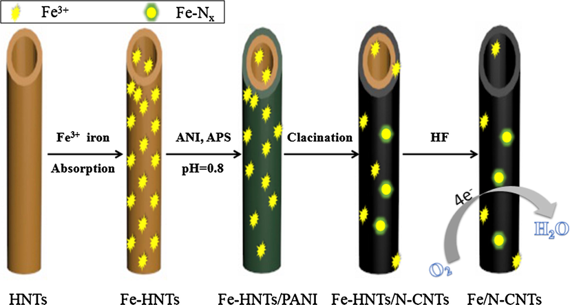
Schematic representation of the preparation processes of Fe/N-CNTs.

(a) TEM and (b) SEM images of Fe/N-CNTs(800). (d, e) SEM-EDS maps of Fe, N, C and O of Fe/N-CNTs(800).
Fig. 2a shows the Fourier transform infrared spectrum of the nanotubes during the preparation process. In addition to the characteristic peaks of Fe-HNTs, a new peak attributed to PANI can be observed in the infrared spectrum of Fe-HNTs/PANI. The details are as follows: at 3695 and 3625 cm−1 in the high frequency region, the tensile vibration peak of O-H of the structural water in the halloysite. (Theng, 1982) In addition to the O-H characteristic peak in the intermediate frequency region, SiO–O stretching vibration peaks appeared at 1101 and 1030 cm−1. (Huang et al., 2016) The peaks at 536 and 471 cm−1 in the low frequency region are attributed to the vibrational absorption of Si–O and Al–O, respectively. (Zuo et al., 2013) After the polyaniline coating is formed, the vibration peak attributed to O–H in the halloysite in the high frequency region almost disappears. This indicates that O–H on the surface of halloysite was destroyed during the induction of polyaniline synthesis. The vibration peaks at 1576 and 1492 cm−1 appearing in the intermediate frequency region are attributed to the characteristic vibrations of the polyaniline quinoid structure and the phenylene structure, respectively. Peaks at 1303 and 1244 cm−1 are attributed to the C–N stretching vibration of the polyaniline skeleton and the doped polyaniline. After calcination of the composite material, the characteristic peak of polyaniline disappeared in the infrared spectrum and became a broad absorption peak appearing around 1590 cm−1. This broad peak is attributed to the vibration of the C=N bond in the anthracene ring and the phenylene ring. When the halloysite frame is removed, the characteristic peaks belonging to the halloysite in the infrared spectrum completely disappear. Combined with the electron micrograph, it can be considered that the template in the synthesized nanotube has been completely removed, and the residual of the template will affect the activity of the material to catalyze oxygen reduction. Furthermore, a new peak at 630 cm−1 in the infrared spectrum of Fe/N-CNTs is attributed to the absorption vibration of Fe–O in magnetite. The catalytic material was characterized by XRD (Fig. 2b). The nitrogen-doped carbon nanotubes prepared by the same method showed characteristic peaks attributable to the (002) and (101) planes of graphite carbon at 26.382° and 44.391°, respectively (JCPDS card no. 41-1487). This is a typical chaotic carbon structure. (Tran et al., 2016) There are no characteristic peaks of any iron-containing compound in the figure. An XRD pattern of iron-nitrogen co-doped carbon nanotubes is shown in Fig. 2b. There are many sharp peaks at the graphite carbon (002) plane, which is due to the fact that iron doping causes new species to appear in the graphite defect. Further, diffraction peaks attributed to Fe3N were observed at 2θ = 41.076° (002), 43.734° (111), and 68.703° (103) (JCPDS card no. 49-1664). A diffraction peak attributed to Fe-C was observed at 2θ = 45.778°, 50.570° and 56.456° (JCPDS card no. 06–0686). A diffraction peak attributed to Fe2O3 was observed at 2θ = 54.089° (116) (JCPDS card no. 33-0664). The results indicate that iron exists in many different forms in nitrogen-doped carbon nanostructures. The catalyst material is composed of a mixture of Fe–N, Fe–C, and Fe–O compounds. Combined with electron microscopy and infrared, it was once again proved that iron-nitrogen co-doped carbon nanotubes were successfully synthesized. In addition, amorphous phase iron species cannot be identified by XRD, so extra Raman and XPS are analyzed for iron and nitrogen content and chemical environment.
(a) FTIR spectra of Fe/N-CNTs. (b) XRD pattern of the Fe/N-CNTs(800) and N-CNTs.
As shown in Fig. 3a, the degree of graphitization of iron-nitrogen co-doped carbon nanotubes was characterized by Raman spectroscopy. All samples showed two broad peaks at ∼1377 and 1587 cm−1, assigned to the D and G bands, respectively. Typically, the intensity ratio of D-band to G-band (ID/IG) is used to qualitatively analyze the degree of graphitization. The D band represents defective and amorphous carbon nanostructures, and the G band represents the in-plane stretching vibration of ordered carbon atom sp2 hybrid. (Zi-Wu et al., 2011; Dae-Soo et al., 2012) Compared with the Raman spectrum of N-CNTs(800), Fe/N-CNTs(700), Fe/N-CNTs(800) and Fe/N-CNTs(900) showed more disorder. This is because iron doping destroys the graphite lattice and exposes the surface to more defects. The results were consistent with HRTEM. Structural disorder and exposed facet defects are important factors affecting the adsorption of intermediates and increasing the electrocatalytic activity of materials. (Stephen and Stevenson, 2005) Comparing the degree of graphitization of three materials, the ID/IG value of Fe/N-CNTs(800) was the smallest. It is proved that Fe/N-CNTs(800) has the highest degree of graphitization. A higher degree of graphitization helps to increase the electrical conductivity of the material, thereby promoting the catalytic oxygen reduction reaction (Shanmugam and Osaka, 2011).
(a) Raman spectra of N-CNTs and Fe/N-CNTs. (b) XPS spectra of Fe/N-CNTs. (c) The analyzed result of Fe and N element in N-Carbon nanotubes. (d) N 1s XPS spectra of Fe/N-CNTs. (e) Fe 2p XPS spectra of Fe/N-CNTs. Relative ratios of various nitrogen types in Fe/N-CNTs. (f) Relative ratios of various nitrogen types in Fe/N-CNTs.
The elemental composition and chemical environment of the material were further analyzed by XPS. Fig. 3b shows the measured spectra of Fe/N-CNTs(700), Fe/N-CNTs(800) and Fe/N-CNTs(900), revealing the presence of C, N, O and Fe. The analytical data found that the nitrogen atomic percentage of Fe/N-CNTs (700), Fe/CNTs (800) and Fe/N-CNTs (900) were 11.92%, 9.88%, and 8.09%, respectively. Analysis of the measured spectral data revealed that the Fe atomic percentage of Fe/N-CNTs(700), Fe/N-CNTs(800) and Fe/N-CNTs(900) were 0.95%, 0.72%, and 0.49% (Fig. 3c). The results show that too high a carbonization temperature will affect the content of hetero atom doping. Using inductively coupled plasma optical emission spectroscopy (ICP-OES) secondary analysis, the iron content was 1.37%, 0.91%, and 0.54%. The test results were slightly higher than those of the XPS analysis. This may be because iron ions were present on both the inner and outer surfaces of the tubular structure. For confirming the presence of Fe in XRD, we performed an analysis of the Fe 2p3/2 spectrum on the same sample (Fig. 3f). The Binding Energy of Fe 2p3/2 in the interval 710 eV to 715 eV suggests the presence of iron oxide. In addition to this, there is a distinct peak due to the Fe-N bond at ∼708 eV. Interestingly, the doping of iron improved the nitrogen content and the nitrogen content increased by about 2% (Fig. S2a). N doping is the key to increasing the activity and selectivity of carbon nanotube catalysts. (Kuanping et al., 2009; Qiu et al., 2011; Strelko et al., 2000) The N 1s spectra of iron-nitrogen co-doped carbon nanotubes were analyzed by AVANTAGE software. Fig. 3d shows the N 1s spectra of different materials. It can be clearly seen that the N 1s spectrum is decomposed and convolved to ∼398, ∼400, and ∼401 eV correspond to pyridine N, pyrrole N and graphitic N. It has been reported in the literature that pyridinic N can improve the initial potential of oxygen reduction, making the reaction more tend to the four-electron transfer pathway. The significance of pyridine nitrogen for promoting oxygen reduction reaction has also been reported. (Lai et al., 2012; Liu et al., 2009) Therefore, we mainly focus on the content of pyridinic N. Comparing the contents of different types of nitrogen, it was found that Fe/N-CNTs(800) had the most pyridinic N (44.23%) (Fig. 3e). The pyridinic N content of the nitrogen-doped carbon nanotubes prepared under the same conditions was only 21.56% (Fig. S2b). Iron doping improves the pyridinic N content. The improvement of the pyridinic N content ensures high oxygen reduction activity.
As shown in Fig. 4a, the adsorption-desorption curves of all samples showed a type IV isotherm curve and a distinct H1 type hysteresis loop appeared in the medium and high pressure regions, demonstrating the ordered mesoporous structure of the sample. The pore structure of the carbon material changes as the heat treatment temperature changes. When the calcination temperature was raised from 700 °C to 900 °C, the specific surface area of the material was reduced from 767 m−2 g−1 to 540 m−2·g−1. Furthermore, the pore size distribution of different materials was analyzed by the BJH (adsorption curve) method. The corresponding average pore diameters were calculated to be 13.7568, 19.4018 and 13.9994 nm (Fig. 4b). Comparing the nitrogen-doped carbon nanotubes (322 m−2 g−1) prepared under the same conditions, the iron doping improved the specific surface area of the nanotubes by about two times. The superior specific surface area may provide more active sites for the catalyst to promote the oxygen reduction reaction.
(a) N2 adsorption-desorption isotherms and (b) pore size distribution of Fe/N-CNTs.
3.2 Electrocatalytic performances
Further explore the process of catalytic oxygen reduction of iron-nitrogen co-doped carbon nanotubes. The material was tested for CV data under alkaline conditions. Fig. S3a-c show cyclic voltammetry curves of Fe/N-CNTs(700), Fe/N-CNTs(800) and Fe/N-CNTs(900) in N2 and O2 saturated electrolyte solutions, respectively. It can be observed that almost no oxygen reduction current exists under the N2-saturated condition, and a significant reduction current occurs when O2 is saturated, which proves the occurrence of oxygen reduction reaction. The reduction potential is concentrated between 0.6 and 0.8 V. When the heat treatment temperature was 800°C, the highest oxygen reduction potential was 0.75 V (Fig. 5a). It is proved that when Fe/N-CNTs(800) catalyzes the oxygen reduction reaction, the reduction reaction is easier to occur. The material was subjected to LSV data testing using a rotating ring disk electrode (RDE). In order to investigate the kinetics and electron transfer number of the oxygen reduction reaction, the LSV curves of the reactions at different rotation speeds (400–2025 rpm) were tested (Fig. S3d-f). It can be observed that as the rotational speed increases, the initial potential of the catalytic reaction of the same catalyst hardly changes, and the limiting current density increases. This demonstrates that the rate of O2 diffusion on the catalyst surface during the reaction has an important effect on the reaction rate. Comparing the LSV curves of the oxygen reduction reactions catalyzed by different materials at 1600 rpm, Fe/N-CNTs(800) had the highest initial potential of ∼0.882 V (Fig. 5c). The half-wave potential of Fe/N-CNTs(800) was calculated to be 0.766 V (Fig. 5b), which is almost identical to commercial Pt/C-20% (0.769 V, Sigma). It exhibited superior oxygen reduction catalytic activity than nitrogen-doped carbon nanotubes without iron (Table 1). Koutecky-Levich (K-L) plots of different catalyst catalytic reactions were calculated from LSV at different speeds (Figure S4). The K-L equation obtained at different electrode potentials of the same catalyst is linear and the slope is basically the same, which proves that the electron transfer number of the unit oxygen molecules is the same at different potentials. The intercept of the K-L equation represents the reaction kinetic current density jk. When the calcination temperature is 800 °C, the maximum jk value is obtained, which corresponds to excellent oxygen reduction activity (Fig. 5d). Fig. 5e plots the Tafel curve of the reaction in the range of 0.6–0.9 V. Through the Tafel slope calculation, Fe/N-CNT (700) is 120.69 mV/decade, Fe/N-CNT (800) is 80.38 mV/decade and Fe/N-CNT(900) is 107.99 mV/decade. The reaction slope of Fe/N-CNTs(800) is the smallest, which proves that the oxygen reduction reaction is most likely to occur under the catalytic conditions of Fe/N-CNTs(800). In order to further confirm the process of oxygen reduction, the ring current and the disk current were measured by the formula (see support information for details) to calculate the peroxide (HO2–) yield and electron transfer number during the oxygen reduction reaction. As shown in Fig. 5f, the HO2– yield was minimal (∼2%) during the oxygen reduction reaction catalyzed by Fe/N-CNTs(800). This yield is much lower than the prepared nitrogen-doped carbon nanotubes because iron doping increases the pyridinic nitrogen content of the catalyst and promotes the four-electron transfer pathway of the reaction (Table 1). The number of electron transfer (n) of Fe/N-CNTs(800) calculated by the formula is stable at ∼3.93 (Fig. 5f).
(a) CV profiles (scanning rate of 20 mV s−1) of all the samples in O2-saturated 0.1 mol·L−1 KOH solutions. (b) LSV curves of all the samples recorded at 1600 rpm in O2-saturated 0.1 mol·L−1 KOH solution. (c) The differential plots of I versus E constructed from the LSV curves. From the sharply increased slope of the plots, the onset potential indicative of the start of the ORR can be clearly seen. (d) K-L plots of different catalysts at 0.3 V. (e) The Tafel curves of N-carbon nanotubes. (f) The electron transfer number (solid line) and Peroxide yield (dotted line) of N-Carbon nanotubes at different potentials.
Samples
Fe atomic percentage (at. %)
N atomic percentage (at. %)
Pyridinic N content (at. %)
Specific surface area (cm2 g−1)
Eonset (V)
Ehalf (V)
n
Fe/N-CNTs(700)
0.95
11.92
31.71
767
0.855
0.73
3.83
Fe/N-CNTs(800)
0.72
9.88
44.23
659
0.882
0.77
3.93
Fe/N-CNTs(900)
0.49
8.09
32.66
540
0.866
0.75
3.88
N-CNTs(900)
6.00
21.65
322
0.862
0.72
3.78
Stability is an important parameter of the catalyst in practical applications. (Fu et al., 2013; Niu et al., 2013) Nitrogen doping enhances the interaction between the metal atom and carbon support, thereby exhibiting superior catalytic stability. Fig. 6 shows the durability tests for Fe/N-CNTs(800) and Pt/C. The LSV curve at 1600 rpm was subjected to 1000 cycles of testing at 20 mV·s−1 in O2– saturated 0.1 mol·L−1 KOH by a voltage of 0.2–1.2 V. Catalyst stability was evaluated based on the degradation of the half-wave potential. It can be clearly seen that the half-wave potential of the Fe/N-CNTs(800) catalyst shows only a negative shift of 8 mV. The degradation of the Pt/C catalyst was 18 mV (Fig. 6a). The results show that the interaction between Fe ions and N is strong enough to give a durable activity of Fe/N–CNTs for ORR. Table 1 summarizes the properties of iron-nitrogen co-doped carbon nanotubes prepared at different heat treatment temperatures, and compares the performance of nitrogen-doped carbon nanotubes studied by our group. It has been found that iron doping provides a superior specific surface area for carbon nanotubes. These values are twice that of nitrogen-doped carbon nanotubes. At the same time, iron doping improves the total nitrogen content and the pyridine nitrogen content in the catalyst material. Among them, Fe-NCNTs(800) showed the best overall performance. The electrochemical stability of Fe/N-CNTs(800) was measured by a chronoamperometric measurements (Figure S5) and the results were similar to the LSV curve. After continuous operation for 20,000 s, the current density of Fe/N-CNTs(800) remained at about 92.8%, which was significantly higher than commercial Pt/C (79.4%), indicating that Fe/N-CNTs(800) has excellent durability to ORR. This may be related to its stable porous structure, providing various means for mass transit. To monitor unwanted methanol crossover of the Fe/N-CNTs(800), chronoampero-metric measurements were conducted (Fig. 6b). After injecting methanol, no significant change was observed in the ORR current density of Fe/N-CNTs(800), which means that it is highly resistant to methanol cross-over effects. In contrast, the ORR current density of commercial Pt/C catalysts is significantly reduced due to the inherent vulnerability of Pt electrocatalysts to methanol.
(a) Stability tests of Fe/N-CNTs(800) and Pt/C catalysts through 1000 potential cycles between 0.3 and 1.2 V at 5 mV s−1. (b) The durability test of Fe/N-CNTs(800) and Pt/C for methanol.
4 Conclusion
Fe3+ is introduced into the polyaniline synthesis process through the unique structural characteristics of halloysite. Polyaniline has excellent electrical conductivity while providing an effective source of nitrogen for the material. The preparation of Fe/N co-doped carbon nanotube materials by such a hard template method for catalytic oxygen reduction has not been reported. The halloysite synergizes with polyaniline to effectively prevent the loss of Fe and N atoms during pyrolysis. Iron-nitrogen co-doped nano-templates prevent agglomeration during polyaniline carbonization, causing the material to expose more graphite defects, resulting in more nitrogen-containing active sites. By changing the calcination temperature, the chemical composition and structural properties of Fe/N-CNTs can be easily adjusted, which has a significant effect on the electrocatalytic performance of ORR. It is worth noting that iron doping greatly improves the specific surface area of the material, resulting in high concentrations of nitrogen doping. The Fe/N-CNTs(800) catalyst had a specific surface area of 659 m−2·g−1 and a pyridinic nitrogen content of 44.23%. It exhibits a higher half-wave potential than Pt/C in alkaline media, including long-term stability. The strategy not only indicates that the use of iron-functionalized halloysite to provide an economical way to prepare iron-nitrogen co-doped carbon nanocatalysts is feasible, and has a guiding significance for the rational design of other ORR catalysts.
Acknowledgements
The work was sponsor by the National Natural Science Foundation of China (21673202), Qing Lan Project and the Priority Academic Program Development of Jiangsu Higher Education Institutions, Advanced Catalysis and Green Manufacturing Collaborative Innovation Center, Changzhou University, Jiangsu Key Laboratory of Advanced Catalytic Materials and Technology (BM2012110), Jiangsu Higher Institutions Key Basic Research Projects of Natural Science (18KJA430003), Graduate Research and Innovation Program of Jiangsu Province (SJCX19_0689), Innovation Team of Six Talent Peaks of Jiangsu Province (XCL-CXTD-029) and Techonology Support Plan of Changzhou (CE 20185031). We would also like to acknowledge the technical support received at the Testing Center of Yangzhou University.
References
- Scalable preparation of sized-controlled Co-N-C electrocatalyst for efficient oxygen reduction reaction. J. Power Sources. 2017;368:46-56.
- [Google Scholar]
- A first-principles study of the role of quaternary-N doping on the oxygen reduction reaction activity and selectivity of graphene edge sites. Top. Catal.. 2013;56:1623-1633.
- [Google Scholar]
- 3D Co-N-doped hollow carbon spheres as excellent bifunctional electrocatalysts for oxygen reduction reaction and oxygen evolution reaction. Appl. Catal. B. 2017;217:477-584.
- [Google Scholar]
- Structure of hybrid materials based on halloysite nanotubes filled with anionic surfactants. J. Phys. Chem. C. 2016;120:13492-13502.
- [Google Scholar]
- Halloysite nanotubes loaded with calcium hydroxide: alkaline fillers for the deacidification of waterlogged archeological woods. ACS Appl. Mater. Interfaces. 2018;10:27355-27364.
- [Google Scholar]
- A structural comparison of halloysite nanotubes of different origin by Small-Angle Neutron Scattering (SANS) and Electric Birefringence. Appl. Clay Sci.. 2018;160:71-80.
- [Google Scholar]
- Halloysite nanotubes for cleaning, consolidation and protection. Chem. Rec.. 2018;18:940-949.
- [Google Scholar]
- Phosphorus-doped ordered mesoporous carbons with different lengths as efficient metal-free electrocatalysts for oxygen reduction reaction in alkaline media. J. Am. Chem. Soc.. 2012;134:16127-16130.
- [Google Scholar]
- FeCo–N x embedded graphene as high performance catalysts for oxygen reduction reaction. Appl. Catal. B. 2013;130:143-151.
- [Google Scholar]
- N-doped-carbon-coated Fe3O4 from metal-organic framework as efficient electrocatalyst for ORR. Nano Energy. 2017;40:462-470.
- [Google Scholar]
- Nitrogen-doped mesoporous network-like carbon as an efficient metal-free electrocatalyst for oxygen reduction reaction. Int. J. Hydrogen Energy. 2016;41:22941-22951.
- [Google Scholar]
- Impact of Cu electrode on switching behavior in a Cu/HfO2/Pt structure and resultant cu ion diffusion. Appl. Phys Express. 2009;2:061401-061403.
- [Google Scholar]
- Oxygen reduction on graphene-carbon nanotube composites doped sequentially with nitrogen and sulfur. ACS Catal.. 2014;4:2734-2740.
- [Google Scholar]
- Facile preparation of halloysite/polyaniline nanocomposites via in situ polymerization and layer-by-layer assembly with good supercapacitor performance. J. Mater. Sci.. 2016;51:4047-4054.
- [Google Scholar]
- Spectroscopic characterization of polyaniline doped with transition metal salts. Synth. Met.. 2006;156:654-663.
- [Google Scholar]
- Spectroscopic insights into the nature of active sites in iron–nitrogen–carbon electrocatalysts for oxygen reduction in acid. Nano Energy. 2016;29:65-82.
- [Google Scholar]
- Constructing highly stretchable and superstable electrode with N-doped double-walled carbon nanotubes/poly(m-phenylene isophthalamide) for oxygen reduction reaction. Chem. Eng. J.. 2017;327:1077-1084.
- [Google Scholar]
- Design of a sectionalized MnO2-Co3O4 electrode via selective electrodeposition of metal ions in hydrogel for enhanced electrocatalytic activity in metal-air batteries. Nano Energy. 2016;30:130-137.
- [Google Scholar]
- Transforming two-dimensional boron carbide into boron and chlorine dual-doped carbon nanotubes by chlorination for efficient oxygen reduction. ACS Energy Lett.. 2018;3:184-190.
- [Google Scholar]
- Nitrogen-doped carbon nanotube arrays with high electrocatalytic activity for oxygen reduction. Science. 2009;323:760-764.
- [Google Scholar]
- Graphene/poly(3,4-ethylenedioxythiophene)/Fe3O4 nanocomposite – an efficient oxygen reduction catalyst for the continuous electricity production from wastewater treatment microbial fuel cells. Int. J. Hydrogen Energy. 2016;41:13208-13219.
- [Google Scholar]
- Exploration of the active center structure of nitrogen-doped graphene-based catalysts for oxygen reduction reaction. Energy Environ. Sci.. 2012;5:7936-7942.
- [Google Scholar]
- An assembly of organic-inorganic composites using halloysite clay nanotubes. Curr. Opin. Colloid Interface Sci.. 2018;35:42-50.
- [Google Scholar]
- Progress in nanostructured (Fe or Co)/N/C non-noble metal electrocatalysts for fuel cell oxygen reduction reaction. Electrochim. Acta. 2018;262
- [Google Scholar]
- Low-temperature synthesis of heterogeneous crystalline TiO2–halloysite nanotubes and their visible light photocatalytic activity. J. Mater. Chem. A. 2013;1:8045-8054.
- [Google Scholar]
- Metal-organic frameworks derived reverse-encapsulation Co-NC@Mo2C complex for efficient overall water splitting. Nano Energy. 2019;57:746-752.
- [Google Scholar]
- Iron-nitrogen dual-doped three-dimensional mesoporous carbons for high-activity electrocatalytic oxygen reduction. Appl. Mater. Today. 2018;13:174-181.
- [Google Scholar]
- Development of non-precious metal oxygen-reduction catalysts for PEM fuel cells based on N-doped ordered porous carbon. Appl. Catal. B. 2009;93:156-165.
- [Google Scholar]
- Controllable synthesis of nitrogen-doped carbon nanotubes derived from halloysite-templated polyaniline towards nonprecious ORR catalysts. Appl. Surf. Sci.. 2019;469:269-275.
- [Google Scholar]
- The application of halloysite tubule nanoclay in drug delivery. Expert Opin Drug Deliv. 2016;13:977-986.
- [Google Scholar]
- Post iron-doping of activated nitrogen-doped carbon spheres as a high-activity oxygen reduction electrocatalyst. Energy Storage Mater.. 2018;13:142-150.
- [Google Scholar]
- Effect of morphology and size of halloysite nanotubes on functional pectin bionanocomposites for food packaging applications. ACS Appl. Mater. Interfaces. 2017;9:17476-17488.
- [Google Scholar]
- Direct preparation of carbon nanofiber electrodes via pyrolysis of iron(II) phthalocyanine: Electrocatalytic aspects for oxygen reduction. J. Phys. Chem. B. 2004;108:11375-11383.
- [Google Scholar]
- Halloysite nanotubes as support for metal-based catalysts. J. Mater. Chem. A. 2017;5:13276-13293.
- [Google Scholar]
- Oxygen reduction reaction catalysts prepared from acetonitrile pyrolysis over alumina-supported metal particles. J. Phys. Chem. B. 2006;110:18374-18384.
- [Google Scholar]
- H. Meng, N. Larouche, M. Lef, egrave, vre, Fr, eacute, eacute, r. Jaouen, B. Stansfield, J.-P. Dodelet, Iron porphyrin-based cathode catalysts for polymer electrolyte membrane fuel cells: effect of NH and Ar mixtures as pyrolysis gases on catalytic activity and stability, Electrochimica Acta 55 (2010) 6450–6461.
- Graphene-based non-noble-metal Co/N/C catalyst for oxygen reduction reaction in alkaline solution. J. Power Sources. 2013;243:65-71.
- [Google Scholar]
- Recent trends on the application of PGM-free catalysts at the cathode of anion exchange membrane fuel cells. Curr. Opin. Electrochem.. 2018;9:240-256.
- [Google Scholar]
- Advances and challenges in alkaline anion exchange membrane fuel cells. Prog. Energy Combust. Sci.. 2018;66:141-175.
- [Google Scholar]
- Co/Al2O3-rGO nanocomposite as cathode electrocatalyst for superior oxygen reduction in microbial fuel cell applications: The effect of nanocomposite composition. Electrochim. Acta. 2017;254:1-13.
- [Google Scholar]
- 3D polymer hydrogel for high-performance atomic iron-rich catalysts for oxygen reduction in acidic. Media. 2017;219:629-639.
- [Google Scholar]
- Nitrogen-doped ultrathin carbon nanofibers derived from electrospinning: large-scale production, unique structure, and application as electrocatalysts for oxygen reduction. J. Power Sources. 2011;196:9862-9867.
- [Google Scholar]
- Transition metal-nitrogen co-doped carbide-derived carbon catalysts for oxygen reduction reaction in alkaline direct methanol fuel cell. Appl. Catal. B. 2017;219:276-287.
- [Google Scholar]
- Pd nanoparticles immobilized on the poly-dopamine decorated halloysite nanotubes hybridized with N-doped porous carbon monolayer: A versatile catalyst for promoting Pd catalyzed reactions. J. Catal.. 2018;42:15733-15742.
- [Google Scholar]
- Efficient electrocatalytic oxygen reduction over metal free-nitrogen doped carbon nanocapsules. Chem. Commun.. 2011;47:4463-4465.
- [Google Scholar]
- Influence of nitrogen doping on oxygen reduction electrocatalysis at carbon nanofiber electrodes. J. Phys. Chem. B. 2005;109:4707-4716.
- [Google Scholar]
- On the mechanism of possible influence of heteroatoms of nitrogen, boron and phosphorus in a carbon matrix on the catalytic activity of carbons in electron transfer reactions. Carbon. 2000;38:1499-1503.
- [Google Scholar]
- Surface Properties of Allophane, Halloysite, and Imogolite. Clays Clay Miner.. 1982;30:143-149.
- [Google Scholar]
- Iron–polypyrrole electrocatalyst with remarkable activity and stability for ORR in both alkaline and acidic conditions: a comprehensive assessment of catalyst preparation sequence. J. Mater. Chem. A. 2016;4:8645-8657.
- [Google Scholar]
- Magnetism of natural composite of halloysite clay nanotubes Al2Si2O5(OH)4 and amorphous hematite Fe2O3. Mater. Charact.. 2017;129:179-185.
- [Google Scholar]
- Formation of metal clusters in halloysite clay nanotubes. Sci. Technol. Adv. Mater.. 2017;18:147-151.
- [Google Scholar]
- A high activity nitrogen-doped carbon catalyst for oxygen reduction reaction derived from polyaniline-iron coordination polymer. J. Power Sources. 2014;266:222-225.
- [Google Scholar]
- Edges of graphene and carbon nanotubes with high catalytic performance for oxygen reduction reaction. PCCP. 2017;19:21003-21011.
- [Google Scholar]
- Morphological and interfacial control of platinum nanostructures for electrocatalytic oxygen reduction. ACS Catal.. 2016;6:5260-5267.
- [Google Scholar]
- Au nanowires@Pd-polyethylenimine nanohybrids as highly active and methanol-tolerant electrocatalysts toward oxygen reduction reaction in alkaline media. ACS Catal.. 2018;8:11287-11295.
- [Google Scholar]
- Polyaniline and perfluorosulfonic acid co-stabilized metal catalysts for oxygen reduction reaction. Langmuir. 2017;33:5353-5536.
- [Google Scholar]
- Interfacial proton enrichment enhances proton-coupled electrocatalytic reactions. J. Mater. Chem. A. 2018;6:17771-17777.
- [Google Scholar]
- Phosphorus-doped graphite layers with high electrocatalytic activity for the O2 reduction in an alkaline medium. Angew. Chem. Int. Ed.. 2011;50:3257-3261.
- [Google Scholar]
- Preparation of polyaniline–polypyrrole binary composite nanotube using halloysite as hard-template and its characterization. Chem. Eng. J.. 2013;228:1092-1097.
- [Google Scholar]
Appendix A
Supplementary material
Supplementary data to this article can be found online at https://doi.org/10.1016/j.arabjc.2020.01.018.
Appendix A
Supplementary material
The following are the Supplementary data to this article:Supplementary data 1
Supplementary data 1


