

Ge modified by metal–organic segments as anodes for Ge-air batteries with an alkaline gel polymer electrolyte
⁎Corresponding author. yuyingjiankmu@163.com (Yingjian Yu)
-
Received: ,
Accepted: ,
This article was originally published by Elsevier and was migrated to Scientific Scholar after the change of Publisher.
Abstract
The advantages of Ge-air batteries compared with metal-air batteries are their high anode utilization and ideal safety. To further enhance the discharge performance of Ge-air batteries, we report for the first time the successful synthesis of metal–organic segments (MOSs) material on the surface of germanium wafers by solution growth methods and demonstrate their performance in a button-type Ge-air battery with an alkaline gel polymer electrolyte. The morphology of MOSs can be controlled by adjusting the solution concentration and reaction time, and the discharge time of the battery would be elevated to about 350 h with prolonged reaction time. Our experimental findings prove that applying this MOSs material at the anode can significantly improve the discharge duration of Ge-air batteries. This paper also provides a strategy for anode modification to ameliorate the performance of Ge-air batteries.
Keywords
Ge-air batteries
Discharging behaviors
Anode modification
Metal–organic segments
Alkaline gel polymer electrolyte

1 Introduction
In recent years, to meet the demand for clean energy in today's society, efforts are being made to develop more stable and effective energy technologies that can maintain human life. Among the various types of batteries, air batteries come into the limelight with their high energy density and the use of oxygen in the air, reducing weight and releasing space (Zhang and Huang, 2020).
Many materials can be used as the anode in air batteries, such as zinc (Duan et al., 2021; Liang et al., 2021), aluminum (Zhu et al., 2021; Li et al., 2021), lithium (Lu and Lu, 2021; Majidi et al., 2022), and silicon (Yu et al., 2021; Yu et al., 2021). Although these air batteries offer high-energy capacities, many challenges remain with these cells (Wang et al., 2023). Among them, some metal anodes (e.g. Zn, Li) would inevitably form dendrites during the discharge process, causing an internal short circuit of the battery (Yan et al., 2021; Lee et al., 2022; Feng et al., 2023); others (e.g. Al, Si) have high self-corrosion rates in alkaline solutions under both open circuit and discharge conditions (Li et al., 2021; Goel et al., 2020; Chen et al., 2022). Compared with the above anode materials, germanium anodes are better in terms of safety, stability, and corrosion resistance (Ocon et al., 2013).
In alkaline electrolytes, there are mainly three reactions in Ge-air batteries during the discharge process. The Ge anode is oxidized to form Ge hydroxide (Eq. (1)); at the same time, the oxygen from the cathode would be reduced to hydroxide ions which diffuse to the anode to complete the battery reaction (Eq. (2)). Ge(OH)4 tend to decompose into germanium oxide through a dehydration reaction, resulting in the passivation of the anode surface and preventing further discharge (Eq. (3)). The Ge anode also reacts with alkaline solutions to produce H2 (Eq. (4)) (Ocon et al., 2014; Zhao et al., 2023).
So far, the research on Ge-air batteries mainly focuses on the influence of doping types, crystal orientations, and etching treatment of Ge anode on the batteries (Ocon et al., 2013; Ocon et al., 2014; Zhao et al., 2023; Ocon et al., 2016; Yu et al., 2019). However, passivation as a factor that can significantly affect the utilization of Ge anodes has not been fully investigated and it is vital to protect the Ge anode to improve the discharge performance (Yu and Hu, 2021).
Metal-organic frameworks (MOFs) belong to coordination polymers, which are connected by the self-assembly of organic ligands and metal ions/clusters through coordination bonds and have stable porous structures (Mukhopadhyay et al., 2021). Over the past decade, more and more researchers have shown that MOFs can be used for electrochemical energy storage and conversion due to their large specific surface area, highly porous, crystalline, and tunable pore structures, realize the application in the fields of secondary cells, supercapacitors, and fuel cell (Zhang et al., 2021; Yan et al., 2021; Meng et al., 2021; Wang et al., 2021; Deng et al., 2023; Yu et al., 2023). In addition, some MOFs (e.g. ZIF-8, MIL-53, and UiO-66) exhibit hydrophobic properties (Dalapati et al., 2021; Roy et al., 2016), good water stability (Gelfand and Shimizu, 2016), and corrosion inhibition properties, and have received attention in the field of anticorrosion materials (Zhang et al., 2018; Liu et al., 2020). The controllable synthesis of MOFs allows studying and tuning their applications.
Metal-organic segments (MOSs) are usually metal–organic complexes that appear during the synthesis of MOFs (Yu et al., 2017). It has similar properties to the corresponding MOFs material and forms a more homogeneous film, which can better coat the surface of germanium sheets. Yu et al. applied MOSs to Si nanorod anodes for lithium-ion batteries and demonstrated that this material had a positive impact on improving electrode capacity and battery life (Yu et al., 2017). Recently, Chen et al. used MOSs materials in Si-air batteries and compared the performance differences between anodes with and without MOSs materials for the first time. The experimental results indicated that the introduction of MOSs can effectively suppress the corrosion rate and passivation of Si anode, thus enhancing the lifespan and specific capacity of Si-air batteries (Chen et al., 2023). Moreover, considering the leakage and evaporation of the electrolyte if the battery uses a liquid electrolyte, we used an alkaline gel polymer electrolyte (GPE) creatively in this work (Chen et al., 2020). A coin-type Ge-air battery was successfully constructed with the alkaline GPE, cooperating with Ge wafers modified by the MOSs material as anodes. Preparation and characterization of MOSs grown on germanium wafers with three different solution concentrations and measurements of discharge performances of Ge-air batteries have been conducted. The experimental results show that, compared with bare Ge anode, performances of batteries with Ge@MOSs anode can be tunable with the MOSs modification.
2 Experimental section
2.1 Materials
All experimental materials were purchased from commercial sources and used directly without further purification. The single-side polished, heavily doped p-type Ge(1 0 0) samples were purchased from Yuanjing Electronic Technology Co., Ltd. (China). Zn(AC)2·2H2O (99%), 2-methylimidazole (98%), and sodium carboxymethylcellulose (CMC) were purchased from Shanghai Aladdin Bio-Chem Technology Co., LTD. (China). KOH (95%) and imidazole (99%) were obtained from Shanghai Macklin Biochemical Co., Ltd. (China). Nafion solution (99%) was obtained from Suzhou Sinero Technology Co., Ltd. (China). Isopropanol was obtained from Xilong Chemical Co., Ltd. (China). The Pt/C was purchased from Suzhou Yilongsheng Energy Technology Co., Ltd. (China). Carbon paper was purchased from Taiwan Carbon Energy Corporation (China).
2.2 Preparation of Ge@MOSs anode
The single-side polished p-type Ge(1 0 0) wafers, approximately 15 mm in diameter, were immersed sequentially in ethanol and deionized water for ultrasonic cleaning for 10 min each. The wafers were further dipped in solution (HCl/H2O (1:3)) for 30 s to remove any organic residue and the surface oxide, then afterward rinsed with distilled water and dried.
The synthesis method of MOSs is based on the previous work (Yu et al., 2017; Chen et al., 2023). At room temperature, different masses of 2-methylimidazole, imidazole, and Zn(AC)2·2H2O were dissolved in 25 mL of H2O, respectively, and were stirred until they were completely dissolved. Initially, the 2-methylimidazole solution and the imidazole solution were mixed evenly, and the polished surface of the germanium sheet was then soaked there for 30 s. Subsequently, the Zn(AC)2·2H2O solution was added to the above-mixed solution and mixed uniformly again. The Ge wafer was taken out after reacting for 4 h or 8 h, rinsed with methanol and deionized water in sequence, and dried in a vacuum environment. In this study, six different anodes were constructed as illustrated in Fig. 1, referred to as Ge@MOSs-1, Ge@MOSs-2, and Ge@MOSs-3 with corresponding reacting times, respectively. The particular parameters are presented in Table 1.
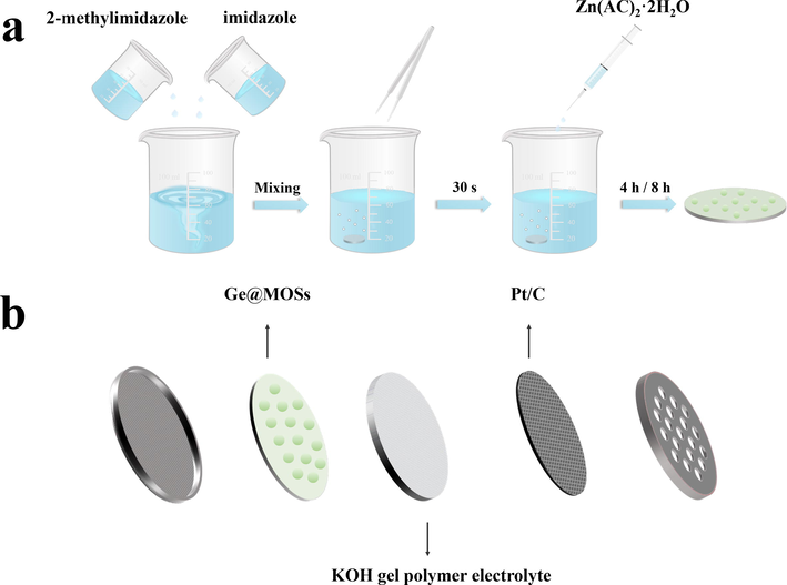
- (a) Preparation flow chart of Ge@MOSs anode; (b) Structure diagram of the coin-type Ge-air battery.
| anodes | 2-methylimidazole | imidazole | Zn(AC)2·2H2O |
|---|---|---|---|
| Ge@MOSs-1 | 0.038 mmol | 0.038 mmol | 0.019 mmol |
| Ge@MOSs-2 | 0.075 mmol | 0.075 mmol | 0.038 mmol |
| Ge@MOSs-3 | 0.113 mmol | 0.113 mmol | 0.056 mmol |
2.3 Characterization
The surface morphology and elemental distribution of Ge@MOSs were displayed by a field emission scanning electron microscope (FE-SEM, Thermoscientific Apreo2C) coupled with an energy dispersive spectrometer detector (EDS, Oxford Ultim Max65). The morphology and roughness of the Ge@MOSs surface were revealed by atomic force microscopy (AFM, Bruker Dimension Icon). Raman spectra were recorded on a Horiba LabRAM HR Evolution instrument ranging from 50 to 4000 cm−1 with a laser source of 532 nm. The surface elemental composition of Ge@MOSs was analyzed using X-ray photoelectron spectroscopy (XPS, Thermoscientific ESCALAB Xi + ). In addition, X-ray diffraction (XRD, Rigaku Ultima IV) was also used to investigate the crystallization of the sample surface.
2.4 Assembly of air batteries
The air cathode consisted of 2.8 mg Pt/C (mg/cm), 700 μL Nafion, and 300 μL isopropanol solution evenly covering carbon fabric. The gel KOH electrolyte was prepared by mixing sodium carboxymethylcellulose (CMC, 15 wt%) with the 6 M KOH solution (85 wt%) and stirring vigorously until the mixture was homogeneous. The battery was assembled with the above-mentioned anode, electrolyte, air cathode, and the CR2032 coin-type air battery housing, as exhibited in Fig. 1.
3 Results and discussion
According to the SEM images (Fig. 2a-f), MOSs with spots appear on the Ge surface and the morphology can be modulated by varying solution concentration and reaction time. It is obvious to notice that the density of spots increases with the reaction time. Additionally, the cross-sectional SEM images of the Ge@MOSs anodes (Fig. 3a-f) reveal that as the concentration of the reaction solution increases, the thickness of MOSs increases from 0.32 to 2.83 μm. As the reaction time prolongs, the thickness of MOSs also slightly increases, and the number of MOSs also significantly increases. This phenomenon is consistent with Chen et al.'s report on MOSs (Chen et al., 2023). The distribution of C, N, and Zn elements obtained by energy-dispersive X-ray spectroscopy (EDS) (Fig. 2g) shows that the equidistribution of MOSs on the surface of the germanium substrate. Topographic details of the composite surfaces characterized by AFM are displayed in Fig. 4. When the reaction time was 4 h, the solution concentration had a tremendous influence on the size of the spots on the surface of Ge@MOSs. As the concentration of the solution increases, the particle size of the circular spot becomes smaller. The particle sizes of the circular spots of Ge@MOSs-1, Ge@MOSs-2, and Ge@MOSs-3 are approximately 8.8 μm, 2.5 μm, and 1.5 μm, respectively. Meanwhile, the higher the solution concentration, the higher the circular spot. The heights of the circular spots of Ge@MOSs-1, Ge@MOSs-2, and Ge@MOSs-3 are around 45.4 nm, 158.6 nm, and 185.7 nm, respectively (Fig. 4a-c). Extending the reaction time to 8 h, the solution concentration had little effect on the particle size of the circular spots on the surface of Ge@MOSs. The particle sizes of the circular spots of Ge@MOSs-1, Ge@MOSs-2, and Ge@MOSs-3 are approximately 4.2 μm, 3.8 μm, and 4.0 μm, respectively. However, the solution concentration has a certain influence on the height of the circular spot. The higher the solution concentration, the higher the circular spot. The heights of the circular spots of Ge@MOSs-1, Ge@MOSs-2, and Ge@MOSs-3 are around 82.5 nm, 116.5 nm, and 121.7 nm, respectively (Fig. 4g-i). Combined with Table 2, it can be found that in addition to the round spots, a thin MOS film is attached to the surface of the Ge wafer, and the roughness of the MOS surface also increases with the reaction time and reaction concentration (Fig. 4d-f and Fig. 4j-k). It is noteworthy that the surface roughness of Ge@MOSs-3 decreases when the reaction time is 8 h. This phenomenon may be caused by the gradual dissolution of the surface particles into thin film after the solution concentration becomes higher and the reaction time becomes longer (Fig. 4l) (Yu et al., 2017).
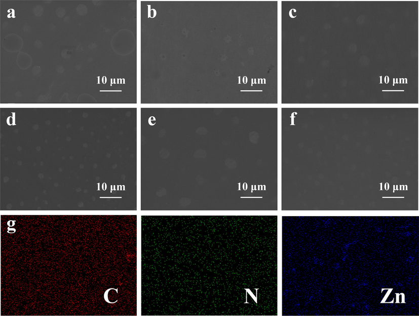
- Top-view SEM images of (a) Ge@MOSs-1, (b) Ge@MOSs-2, and (c) Ge@MOSs-3 with 4 h reaction time; Top-view SEM images of (d) Ge@MOSs-1, (e) Ge@MOSs-2, and (f) Ge@MOSs-3 with 8 h reaction time; (g) EDS elemental mappings of C, N, Zn of Ge@MOSs-2 with 4 h reaction time.
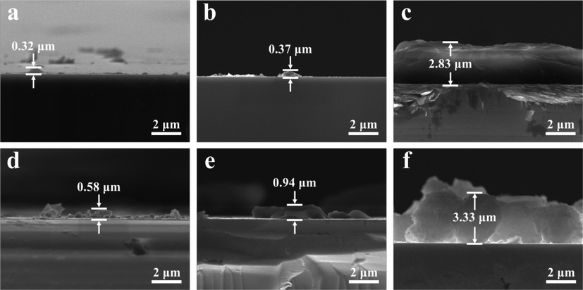
- Cross-sectional SEM images of (a) Ge@MOSs-1, (b) Ge@MOSs-2, and (c) Ge@MOSs-3 with 4 h reaction time; Cross-sectional SEM images of (d) Ge@MOSs-1, (e) Ge@MOSs-2, and (f) Ge@MOSs-3 with 8 h reaction time.
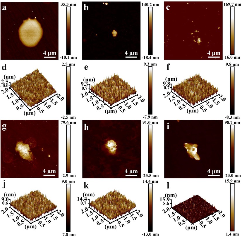
- AFM images of the top surface of (a) Ge@MOSs-1, (b) Ge@MOSs-2, and (c) Ge@MOSs-3 with 4 h reaction time; 3D AFM image of (d) Ge@MOSs-1, (e) Ge@MOSs-2, and (f) Ge@MOSs-3 in areas other than the circular spot area with 4 h reaction time; AFM images of the top surface of (g) Ge@MOSs-1, (h) Ge@MOSs-2, and (i) Ge@MOSs-3 with 8 h reaction time; 3D AFM image of (j) Ge@MOSs-1, (k) Ge@MOSs-2, and (l) Ge@MOSs-3 in areas other than the circular spot area with 4 h reaction time.
| Rq | Ge@MOSs-1 | Ge@MOSs-2 | Ge@MOSs-3 |
|---|---|---|---|
| 4 h | 0.71 nm | 2.44 nm | 2.57 nm |
| 8 h | 2.37 nm | 3.90 nm | 1.38 nm |
The XRD patterns of the Ge@MOSs are shown in Fig. 5a. The materials synthesized under different conditions have diffraction peaks at 66°, which correspond to the crystal planes (1 0 0) of the germanium sheet that is consistent with previously reported work (Ocon et al., 2016). No other peak is found in Fig. 5a, which is most likely due to the fact that MOSs are amorphous materials. According to Fig. 5b-c, a prominent peak appears at 296.6 cm−1, corresponding to the Ge-Ge bond. Additionally, a broad peak appears at 550 ∼ 600 cm−1, which can be assigned to the N—H bond (Foley and Enescu, 2007).
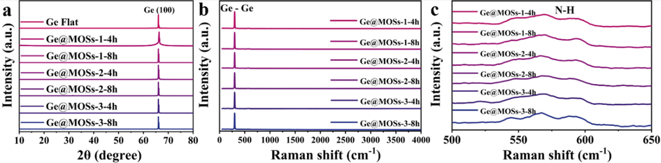
- (a) XRD pattern and (b,c) Raman spectrum of the prepared Ge@MOSs sample.
To further reveal the elemental composition and chemical bond state, Ge@MOSs were analyzed by XPS. The five prominent peaks at 29.4 eV, 284.5 eV, 398.1 eV, 531.0 eV, and 1021.8 eV of the XPS full spectrum in Fig. 6a correspond to the orbitals of Ge3d, C1s, N1s, O1s, and Zn2p, respectively, indicating the existence of these elements. The presence of elemental oxygen may be attributed to the exposure of the sample to air. Fig. 6b is the high-resolution XPS spectrum of N1s. As can be seen from the profile, there are four prominent peaks at 399.5 eV, 401.1 eV, 402.7 eV, and 405.1 eV assigning to the orbits of pyridinic-N, pyrrolic-N, graphitic-N, and oxidic-N (Cai et al., 2019). Among them, the existence of the pyrrolic-N orbital indicates that there is a coordination relationship between N on the ligand and the metal ion Zn2+. Fig. 6c shows the high-resolution XPS spectrum of Zn2p. The two prominent peaks at 1022.5 eV and 1045.7 eV assign to the Zn2p3/2 orbit and Zn2p1/2 orbit respectively (He et al., 2019). The existence of these two orbits further proves that coordination bonds are formed between metal ions Zn2+ and organic ligands and MOSs are successfully synthesized.
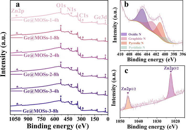
- (a) Wide-scanned XPS spectrum of Ge@MOSs; (b) High-resolution XPS spectrum of Zn2p;(c) High-resolution XPS spectrum of N1s.
After assembling different anodes into the batteries, electrochemical tests were carried out. Firstly, we obtained the Tafel curves of bare Ge flat, Ge@MOSs-1, Ge@MOSs-2, and Ge@MOSs-3 at reaction time of 4 and 8 h, respectively (Fig. 7a-b). Table 3 displays the corrosion potential (Ecorr) and corrosion current density (Icorr) of different anodes. The corrosion current density of bare Ge flat is 6.685 × 10⁻⁵, while the corrosion current densities of Ge@MOSs-1(with a reaction time of 4 h), Ge@MOSs-2(4 h), and Ge@MOSs-3 (4 h) are 5.592 × 10⁻⁵, 2.892 × 10⁻⁵, and 8.838 × 10⁻⁶, respectively, which are all lower than bare Ge flat. And as the reaction concentration and time increase, their corrosion current densities decrease, indicating that their corrosion resistance are enhanced. Subsequently, we further explored the interfacial charge transfer impedance of different anodes in the batteries using electrochemical impedance spectroscopy (EIS) (Fig. 7d-e). Equivalent circuit fitting on the Nyquist plots obtained from the test is shown in Fig. 7c, where Rs as the solution impedance and Rct as the charge transfer impedance. The data in Table 4 displays that with the prolongation of reaction solution concentration and time, the charge transfer impedance of Ge@MOSs anodes slightly increases, which is higher than that of bare Ge flat. The increase in charge transfer impedance of Ge@MOSs-3 is the most significant compared with other anodes. Moreover, Fig. 8 displays the hydrophilicity of different anodes. As the reaction concentration and time increase, the contact angle of Ge@MOSs anodes to water continuously increases, exhibiting repulsion towards the water. The above tests have proven that MOSs materials can improve the corrosion resistance of anodes and it would be beneficial for battery life. However, due to the insulation properties of the MOSs itself, the introduction of MOSs will also increase the charge transfer impedance, which has a negative impact on working voltages to some extent.
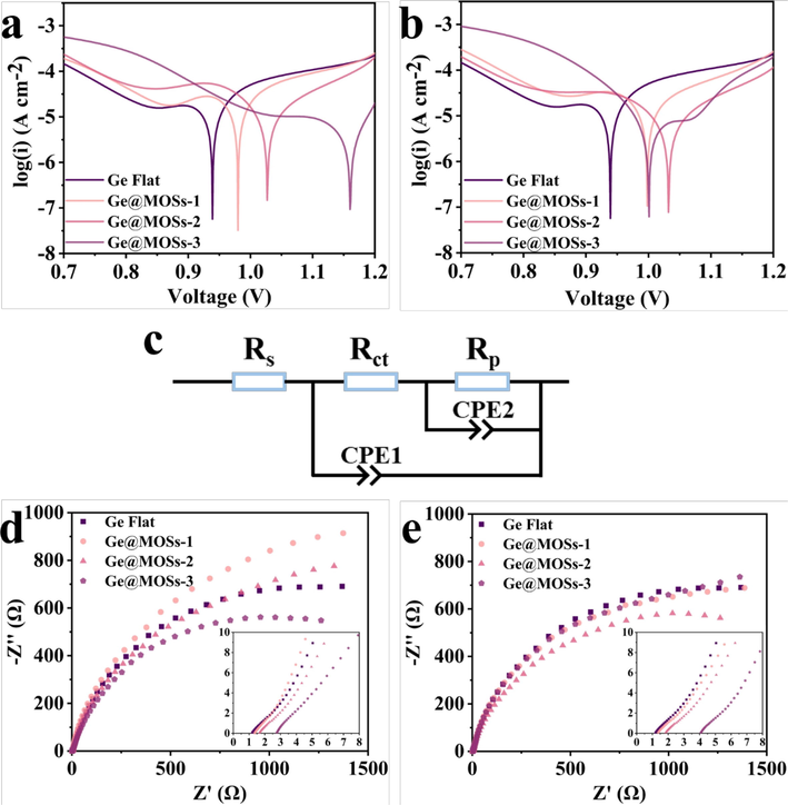
- Tafel curves of Ge flat, Ge@MOSs-1, Ge@MOSs-2, and Ge@MOSs-3 when the reaction time is (a) 4 h and (b) 8 h; (c) The equivalent circuit diagram for fitting EIS; Nyquist plots of Ge flat, Ge@MOSs-1, Ge@MOSs-2, and Ge@MOSs-3 when the reaction time is (d) 4 h and (e) 8 h.
| anodes | Icorr (A cm−2) | Ecorr (V) | |
|---|---|---|---|
| / | Ge Flat | 6.685
|
0.9386 |
| 4 h | Ge@MOSs-1 | 5.592
|
0.9804 |
| Ge@MOSs-2 | 2.892
|
1.0271 | |
| Ge@MOSs-3 | 8.838
|
1.1608 | |
| 8 h | Ge@MOSs-1 | 4.751
|
0.9981 |
| Ge@MOSs-2 | 1.608
|
1.0327 | |
| Ge@MOSs-3 | 6.467
|
1.0016 |
| anodes | Rs (Ω cm−2) | Rct (Ω cm−2) | |
|---|---|---|---|
| / | Ge Flat | 1.254 | 3.080 |
| 4 h | Ge@MOSs-1 | 1.417 | 3.105 |
| Ge@MOSs-2 | 1.717 | 3.902 | |
| Ge@MOSs-3 | 2.801 | 5.864 | |
| 8 h | Ge@MOSs-1 | 1.420 | 3.464 |
| Ge@MOSs-2 | 1.875 | 4.265 | |
| Ge@MOSs-3 | 4.108 | 6.505 |
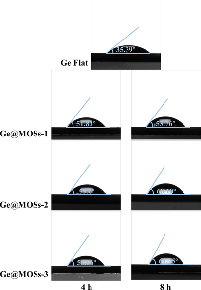
- Contact angles of H2O on the bare Ge flat, Ge@MOSs-1, Ge@MOSs-2, and Ge@MOSs-3.
Ge-air cells were then assembled using the Ge@MOSs samples, and their electro-oxidative behavior as a reactive anode was investigated. The following tests were repeated for several times to exclude the contingency of the experimental results. Fig. 9 reveals the discharge curves of four different anodes at current densities of 65 μA·cm−2, 97.5 μA·cm−2, and 130 μA·cm−2, with reaction time of 4 and 8 h, respectively. Two sets of data were provided under the same experimental conditions. For the convenience of comparison, the discharge data of the two sets of Ge flat in Fig. 9a-c are consistent with those in Fig. 9d-f. First of all, the batteries were tested at a current density of 65 μA·cm−2. It can be found from Fig. 9a and 9d that the bare Ge wafer anode stops discharging after about 163 h, while for Ge@MOSs-1 and Ge@MOSs-2, their discharge time is significantly prolonged. When the reaction time is 4 h, the discharge time of Ge@MOSs-1 as the anode is about 216 h, and the discharge time of Ge@MOSs-2 as the anode is about 320 h (Fig. 9a). Compared with bare Ge, the discharge duration is increased by approximately 33% and 96%, respectively. When the reaction time is 8 h, the discharge time of Ge@MOSs-1 as the anode is about 246 h, and the discharge time of Ge@MOSs-2 as the anode is about 360 h (Fig. 9d). Compared with bare Ge, the discharge duration is increased by approximately 51% and 121%, respectively. It is worth noting that the discharge time of Ge@MOSs-3 (4 h) and Ge@MOSs-3 (8 h) are about 95 h and 136 h, respectively, which are shorter than that of bare Ge flat (around 163 h). Observing Fig. 9b-c and 9e-f, when the current density is 97.5 μA·cm−2, the battery lifespan of Ge@MOSs-1 (4 h) and Ge@MOSs-2 (4 h) as anodes is around 158 h and 185 h, respectively, which is longer than that of bare Ge flat (around 139 h). The discharge duration of Ge@MOSs-3 (4 h) is approximately 77 h shorter than that of bare Ge flat. When the current density is 130 μA·cm−2, the battery lifespan of Ge@MOSs-1 (4 h) and Ge@MOSs-2 (4 h) as anodes is around 80 h and 131 h, respectively, which is longer than that of bare Ge flat (around 60 h). The discharge duration of Ge@MOSs-3 (4 h) is approximately 29 h shorter than that of bare Ge flat. When the reaction time is increased to 8 h, the discharge duration of the three anodes is slightly longer than those of 4 h. However, even if the discharge duration of Ge@MOSs-3 is increased by enhancing reaction time, it is still shorter than that of bare Ge flat. This phenomenon is consistent with a current density of 65 μA·cm−2. By comparing the discharge time of Ge@MOSs-1, Ge@MOSs-2, and Ge@MOSs-3 as anodes when the reaction time is 4 h and 8 h, it can be concluded that the reaction time of 8 h is more effective for increasing the discharge time of Ge-air batteries. It is worth noting that when two kinds of the Ge@MOSs-3 anode are used, the discharge time of corresponding batteries is shorter than the Ge@MOSs-1 and Ge@MOSs-2 anodes. As mentioned above, more MOSs material would be attached to the surface of the germanium sheet if the concentration of the reaction solution is enhanced. However, the insulation of the MOSs material blocks the flow of electrons and too much MOSs material makes the Ge anode harder to contact with the electrolyte, resulting in a shorter discharge time of the Ge-air battery.
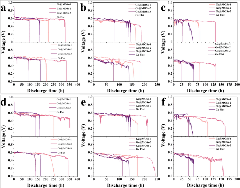
- Two sets of galvanostatic discharge curves of Ge@MOSs-1, Ge@MOSs-2, Ge@MOSs-3, and Ge flat samples as anodes at the current density of (a) 65 μA cm−2, (b) 97.5 μA cm−2, and (c) 130 μA cm−2 when the reaction time is 4 h; Two sets of galvanostatic discharge curves of Ge@MOSs-1, Ge@MOSs-2, Ge@MOSs-3, and Ge flat samples as anodes at the current density of (d) 65 μA cm−2, (e) 97.5 μA cm−2, and (f) 130 μA cm−2 when the reaction time is 8 h.
In order to gain a more intuitive understanding of the battery's reaction during discharge, we used SEM to observe the top-view and cross-sectional morphology of different anodes after discharging for 24 and 48 h, as shown in Figs. 10-11. By comparing the morphology of the surface passivation layer of bare Ge flat, Ge@MOSs-1, Ge@MOSs-2, and Ge@MOSs-3, we clearly found that the passivation layer of bare Ge flat is more irregular (Fig. 10a-b and Fig. 11a-b). Meanwhile, the passivation layer of Ge@MOSs is thinner, and it adheres evenly and smoothly to the anode surface. When the reaction time is 8 h, the passivation layer of Ge@MOSs anodes is thinner than that of the composite anodes with the reaction time of 4 h (Fig. 10c-n and Fig. 11c-n). Fig. 12 reveals the EDS spectra of bare Ge flat and Ge@MOSs-2 (with a reaction time of 8 h) as battery anodes after discharging for 24 and 48 h. Table 5 displays the corresponding element contents. The oxygen element content on the surface of Ge@MOSs-2 is lower than that of bare Ge flat, and its increase in oxygen element from 24 h to 48 h of discharge is also smaller than that of bare Ge flat, indicating that the passivation can be restrained by the MOS coating.
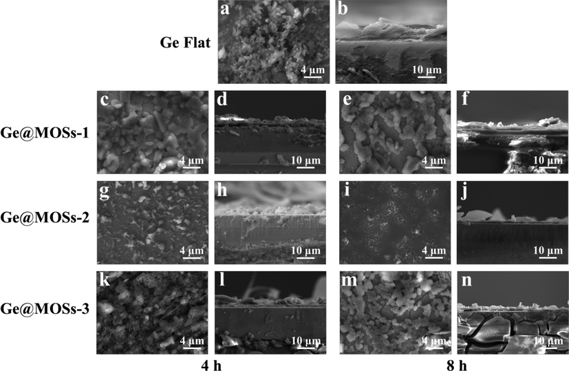
- (a)Top-view and (b) cross-section SEM images of Ge flat after 24 h of discharge; Top-view SEM images of (c) Ge@MOSs-1 (4 h), (e) Ge@MOSs-1 (8 h), (g) Ge@MOSs-2 (4 h), (i) Ge@MOSs-2 (8 h), (k) Ge@MOSs-3 (4 h), and (m) Ge@MOSs-3 (8 h) after discharging for 24 h; Cross-section SEM images of (d) Ge@MOSs-1 (4 h), (f) Ge@MOSs-1 (8 h), (h) Ge@MOSs-2 (4 h), (j) Ge@MOSs-2 (8 h), (l) Ge@MOSs-3 (4 h), and (n) Ge@MOSs-3 (8 h) after discharging for 24 h.
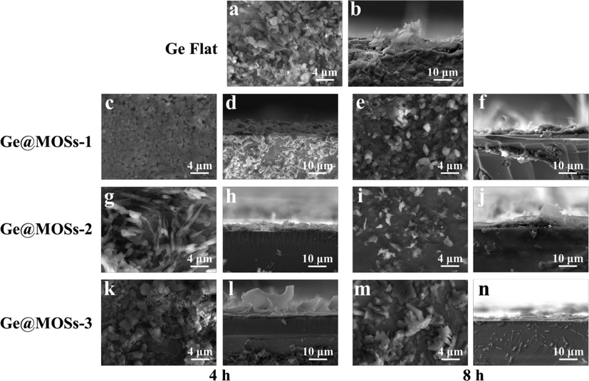
- (a)Top-view and (b) cross-section SEM images of Ge flat after 48 h of discharge; Top-view SEM images of (c) Ge@MOSs-1 (4 h), (e) Ge@MOSs-1 (8 h), (g) Ge@MOSs-2 (4 h), (i) Ge@MOSs-2 (8 h), (k) Ge@MOSs-3 (4 h), and (m) Ge@MOSs-3 (8 h) after discharging for 48 h; Cross-section SEM images of (d) Ge@MOSs-1 (4 h), (f) Ge@MOSs-1 (8 h), (h) Ge@MOSs-2 (4 h), (j) Ge@MOSs-2 (8 h), (l) Ge@MOSs-3 (4 h), and (n) Ge@MOSs-3 (8 h) after discharging for 48 h.
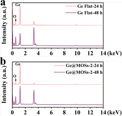
- EDS spectra of (a) Ge flat and (b) Ge@MOSs-2 (8 h) as battery anodes after 24 and 48 h of discharge.
| Discharge time | O (wt%) | Ge (wt%) | |
|---|---|---|---|
| Ge Flat | 24 h | 16.88 | 55.45 |
| 48 h | 35.95 | 31.17 | |
| Δwt% | 19.07 | −24.28 | |
| Ge@MOSs-2 | 24 h | 12.51 | 65.34 |
| 48 h | 29.18 | 36.90 | |
| Δwt% | 16.67 | −28.44 |
Combined with the above characterization, it can be well proved that the right amount of MOSs on the surface of the germanium sheet can improve the utilization rate of the anode. As depicted in Fig. 13, when bare Ge flat is used as the anode of the battery, the alkaline electrolyte will come into direct contact with the Ge surface, resulting in the corrosion of the anode and reduced utilization. Concurrently, the germanium dioxide passivation layer will directly accumulate on the germanium surface, resulting in the complete isolation of the anode and the electrolyte, and the discharge process will be prematurely terminated. In contrast, an appropriate amount of MOSs material will curb the occurrence of corrosion and reduce the direct accumulation of the passivation layer of the germanium anode, while allowing hydroxide ions to pass through the MOSs protective layer and continue to react with the anode, increasing the lifespan and specific capacity of batteries.
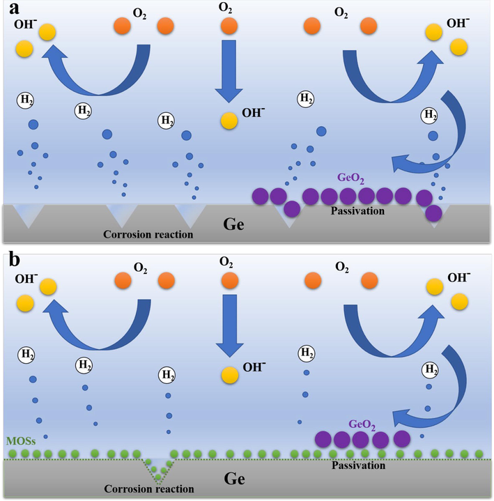
- Diagram of discharge mechanisms of (a) bare Ge and (b) Ge@MOSs as anodes in Ge-air batteries.
4 Conclusion
In this work, Ge modified by MOSs as anodes for button-type Ge-air batteries with an alkaline gel polymer electrolyte have been explored for the first time. The morphologies and discharge behaviors of Ge@MOSs samples prepared under different conditions as anodes have been systematically analyzed. The MOSs material attached to the surface of the Ge wafer will form a thin film and circular spots, and the morphology can be modulated by synthesis conditions. It has been demonstrated that Ge@MOSs-2 as the anode exhibits the best discharging behavior when the reaction time is 8 h. Compared with bare Ge anode, the lifespan of Ge-air battery is increased by approximately 121% to 360 h at a current density of 65 μA·cm−2. The prolongation of the discharge time is due to the modification and protection of anode by the MOSs material in Ge-air batteries, which can effectively suppress the occurrence of corrosion, improve the utilization efficiency of the germanium anode, and alleviate the direct accumulation of passivation layer on Ge surface. This study shows that MOFs and their derived materials have significant application prospects in the field of anode protection of Ge-air batteries and provides experimental ideas for the design of composite germanium anodes in the future.
CRediT authorship contribution statement
Yuhang Zhang: Writing – original draft, Investigation, Visualization, Data curation. Shaoshuai Gao: Writing – original draft, Investigation, Visualization, Data curation. Tingyu Zhao: Resources. Danshuo Chen: Resources. Rongli Wang: Resources. Yingjian Yu: Conceptualization, Methodology, Validation, Formal analysis, Writing – original draft, Writing – review & editing, Supervision, Funding acquisition.
Acknowledgement
This work was financially supported by the National Natural Science Foundation of China (No. 61904073), Spring City Plan-Special Program for Young Talents (ZX20210014), Yunnan Talents Support Plan for Yong Talents, Yunnan Local Colleges Applied Basic Research Projects (202101BA070001-138), Key Laboratory of Artificial Microstructures in Yunnan Higher Education.
Declaration of Competing Interest
The authors declare that they have no known competing financial interests or personal relationships that could have appeared to influence the work reported in this paper.
References
- A highly conductive MOF of graphene analogue Ni3 (HITP)2 as a sulfur host for high-performance lithium-sulfur batteries. Small. 2019;15:1902605.
- [Google Scholar]
- Investigation of the discharging behaviors of differently doped silicon nanowires in alkaline Si-air batteries. J. Ind. Eng. Chem.. 2022;112:271-278.
- [Google Scholar]
- Si protected by metal-organic segments as anodes in Si-air batteries. Surf. Interfaces. 2023;38:102777
- [Google Scholar]
- Metal-organic framework (MOF) derived recyclable, superhydrophobic composite of cotton fabrics for the facile removal of oil spills. ACS Appl. Mater. Interfaces. 2021;13:8563-8573.
- [Google Scholar]
- Conductive metal-organic frameworks for rechargeable lithium batteries. Batteries. 2023;9:109.
- [Google Scholar]
- MOF-derived Co-MOF, O-doped carbon as trifunctional electrocatalysts to enable highly efficient Zn–air batteries and water-splitting. J. Energy Chem.. 2021;56:290-298.
- [Google Scholar]
- Progress and prospect of Zn anode modification in aqueous zinc-ion batteries: experimental and theoretical aspects. Molecules. 2023;28:2721.
- [Google Scholar]
- A Raman spectroscopy and theoretical study of zinc–cysteine complexation. Vib. Spectrosc.. 2007;44:256-265.
- [Google Scholar]
- Parameterizing and grading hydrolytic stability in metal-organic frameworks. Dalton Trans.. 2016;45:3668-3678.
- [Google Scholar]
- In-situ rooting ZnSe/N-doped hollow carbon architectures as high-rate and long-life anode materials for half/full sodium-ion and potassium-ion batteries. Energy Storage Mater.. 2019;23:35-45.
- [Google Scholar]
- Material design and surface chemistry for advanced rechargeable zinc-air batteries. Chem Sci. 2022;13:6159-6180.
- [Google Scholar]
- Rare earth insitu-doped ZIF-67 derived N doped C encapsulated Sm2O3/Co nanoparticles as excellent oxygen reduction reaction catalyst for Al-air batteries. J. Power Sources. 2021;482:229052
- [Google Scholar]
- FeNi nanoparticles encapsulated in Nitrogen-doped carbon frame for efficient and stable Al-air batteries. Mater. Lett.. 2021;296:129890
- [Google Scholar]
- Pt/Zn heterostructure as efficient air-electrocatalyst for long-life neutral Zn-air batteries. Sci. China Mater.. 2021;64:1868-1875.
- [Google Scholar]
- Probe into metal-organic framework membranes fabricated via versatile polydopamine-assisted approach onto metal surfaces as anticorrosion coatings. Corros. Sci.. 2020;177:108949
- [Google Scholar]
- Pouch-type hybrid Li-air battery enabled by flexible composite lithium-ion conducting membrane. J. Power Sources. 2021;489:229431
- [Google Scholar]
- Nanostructured conductive metal organic frameworks for sustainable low charge overpotentials in Li-air batteries. Small. 2022;18:2102902.
- [Google Scholar]
- 2D conductive MOFs with sufficient redox sites: reduced graphene oxide/Cu-benzenehexathiolate composites as high capacity anode materials for lithium-ion batteries. Nanoscale. 2021;13:7751-7760.
- [Google Scholar]
- Assembly of a metal-organic framework (MOF) membrane on a solid electrocatalyst: Introducing molecular-level control over heterogeneous CO2 reduction. Angew. Chem. Int. Edit.. 2021;60:13423-13429.
- [Google Scholar]
- An etched nanoporous Ge anode in a novel metal-air energy conversion cell. Phys. Chem. Chem. Phys.. 2013;15:6333-6338.
- [Google Scholar]
- Quasi-perpetual discharge behaviour in p-type Ge-air batteries. Phys. Chem. Chem. Phys.. 2014;16:22487-22494.
- [Google Scholar]
- High-power-density semiconductor-air batteries based on P-type germanium with different crystal orientations. ChemElectroChem. 2016;3:242-246.
- [Google Scholar]
- Self-cleaning MOF: realization of extreme water repellence in coordination driven self-assembled nanostructures. Chem. Sci.. 2016;7:2251-2256.
- [Google Scholar]
- Proton conduction of Nafion hybrid membranes promoted by NH3-modified Zn-MOF with host-guest collaborative hydrogen bonds for H2/O2 fuel cell applications. ACS Appl. Mater. Interfaces. 2021;13:7485-7497.
- [Google Scholar]
- In/Ga-Doped Si as anodes for Si–Air Batteries with restrained self-corrosion and surface passivation: a first-principles study. Molecules. 2023;28:3784.
- [Google Scholar]
- Immobilizing redox-active tricycloquinazoline into a 2D conductive metal-organic framework for lithium storage. Angew. Chem. Int. Edit.. 2021;60:24467-24472.
- [Google Scholar]
- Applying transfer learning with convolutional neural networks to identify novel electrolytes for metal air batteries. Comput. Theor. Chem.. 2021;1205:113443
- [Google Scholar]
- The applications of semiconductor materials in air batteries. Chin. Chem. Lett.. 2021;32:3277-3287.
- [Google Scholar]
- Si nanorod arrays modified with metal-organic segments as anodes in lithium-ion batteries. RSC Adv.. 2017;7:53680-53685.
- [Google Scholar]
- The surface passivation of Ge(100) and Ge(111) anodes in Ge-air batteries with different doping types and concentrations. RSC Adv.. 2019;9:39582-39588.
- [Google Scholar]
- Germanium-modified silicon as anodes in Si–Ge air batteries with enhanced properties. J. Phys. Chem. Solids. 2021;157:110226
- [Google Scholar]
- Si modified by Zn and Fe as anodes in Si-air batteries with ameliorative properties. J. Alloys Compd.. 2021;883:160902
- [Google Scholar]
- First-principles study of ZIF-8 as anode for Na and K ion batteries. Colloids Surf. A. 2023;659:130802
- [Google Scholar]
- A comprehensive review on the development of solid-state metal-air batteries operated on oxide-ion chemistry. Adv. Energy Mater.. 2020;11:2000630.
- [Google Scholar]
- Constructing ultra-thin Ni-MOF@NiS2 nanosheets arrays derived from metal organic frameworks for advanced all-solid-state asymmetric supercapacitor. Mater. Res. Bull.. 2021;137:111186
- [Google Scholar]
- Insights into the use of metal-organic framework as high-performance anticorrosion coatings. ACS Appl. Mater. Interfaces. 2018;10:2259-2263.
- [Google Scholar]
- Graphene-coated Ge as anodes in Ge-air batteries with enhanced performance. Carbon. 2023;205:86-96.
- [Google Scholar]
- Improvement of electrochemical performance with amphoteric surfactants for Al anode of Al-air battery in alkaline system. J. Power Sources. 2021;515:230646
- [Google Scholar]


