

Translate this page into:
Green synthesis of hematite/TUD-1 nanocomposite as efficient photocatalyst for bromophenol blue and methyl violet degradation
⁎Corresponding author. isfatimah@uii.ac.id (Is Fatimah)
-
Received: ,
Accepted: ,
This article was originally published by Elsevier and was migrated to Scientific Scholar after the change of Publisher.
Peer review under responsibility of King Saud University.
Abstract
Hematite immobilized on TUD-1 nanocomposite was prepared via sol-gel composite formation of biosynthesized hematite nanoparticles with TUD-1 precursor. The nanocomposite was characterized by various techniques such as X-ray diffraction, scanning electron microscopes/energy-dispersive X-ray spectroscopy, transmission electron microscope, gas sorption analysis, and UV–Visible diffuse reflectance spectrophotometer. Photocatalytic activity of the nanocomposite was examined in bromophenol blue and methyl violet degradation. The results showed that hematite nanoparticles obtained by the biosynthesis has particle size ranging at 20–100 nm. The nanocomposite of hematite/TUD-1 exhibit the homogeneous dispersion of the hematite in the mesoporous structured TUD-1. The smaller dispersed hematite nanoparticles affects to the increasing band gap energy of hematite, and is responsible for the efficient photocatalytic degradation of bromophenol blue and methyl violet. It is found that degradation efficiencies of the reactions over hematite/TUD-1 nanocomposite are 94.6% for bromophenol blue, and 96.7% for methyl violet. The degradation efficiency and kinetics constant of the degradation reaction expressed the effectiveness of the nanocomposite since the values are comparable with the hematite nanoparticles and other reported photocatalysts.
Keywords
Hematite
TUD-1
Photocatalysis
Dye degradation

1 Introduction
Photocatalysis is an important technique for some applications such as in energy and environmental applications. Particularly, for environmental purposes, photocatalysis is the core method involved in the advance oxidation process (AOPs) which is an emerging method for organic contaminated-wastewater treatment(Yaseen and Scholz, 2019; Zuorro et al., 2019). A series of metal oxide semiconductors were developed for an economic, sustainable and reusable photocatalysts. Despite of some engineered method for metal oxide synthesis, designing metal oxide photocatalyst in the form of nanoparticles and its dispersion into solid supports are good strategies for those goals (Theerthagiri et al., 2018; Ye et al., 2019). Refer to the quantum size effect, metal oxide in the nanoparticles form has higher capability to catch the photon due to the electronic state of the nanoparticles plasmon resonance (Liu et al., 2017a,b).
Within this scheme, for the green chemistry perspective, designed green syntheses of metal oxide nanoparticles were attempted (Asoufi et al., 2018). For example, green synthesis of hematite on the use of plants extracts has been reported to be a plausible enhanced photocatalytic activity referred to its nanosize-form (Ahmmad et al., 2013; Alagiri and Hamid, 2014; Ma et al., 2019). Attachement or dispersion of nanoparticles into a stable mesoporous material was reported to be effective for photocatalysis due to the increasing charge separation and suppresses the charge recombination within the energy level within the semiconductor (Lei et al., 2018; Meng et al., 2013; Sahoo et al., 2015). Technische Universiteit Delft (TUD-1) is a three dimensional mesoporous silicate synthesised at 2001 by (Telalović et al., 2010). It has a sponge-like pore structure and irregular. Its high specific surface area and mesoporosity are the potency to be metal and metal oxide support for such catalysis applications.
Several metals have been reported to be supported into TUD-1 for catalytic activity enhancement. For example, supported Zr- and Hf-TUD-1, are notified as the efficient heterogeneous catalysts for solketal synthesis from of glycerol and acetone (Li et al., 2015). The catalytic activity enhancement came from the synergistic effect obtained due to the homoegenous distribution of metal, as similarly reported by the supporting Co, Fe and Cu for hydroxylation catalyst, and for Fe2O3 in Friedel-Craft alkylation (Arafat and Bamufleh, 2014; Hamdy et al., 2005). The other most important thing for eco-friendly point of view is that the supported catalyst and photocatalysts were suffered from leaching of the metal/metal oxide active component to have its reusability (Arafat and Bamufleh, 2014). According to these considerations for photocatalytic activity enhancement, this research aimed to synthesize Fe2O3 (hematite) supported on TUD-1 or called as hematite/TUD-1 nanocomposite. Parkia speciossa hassk pod extract (furthermore called as PSE) was chosen as bioreductor refer to previous investigation on its capability in the synthesis of silver nanoparticles, SnO2 nanoparticles, and magnetic nanoparticles (Fatimah, 2016; Fatimah et al., 2020). In different perspective of exploration on stable photocatalyst, this research was focusing on physicochemical study to the green synthesized hematite nanoparticles (HNPs) and its metal loading onto TUD-1. The synthesis of TUD-1 and the nanocomposite was conducted by sol-gel formation using tetraethyl orthosilicate as precursor, cetyl trimethyl ammonium and triethanol amine as surfactant and co-surfactant. Moreover, physicochemical character of the nanocomposite and its effect on photocatalytic activity was evaluated in bromophenol blue (BPB) and methyl violet (MV) degradation are the aim of this research.
2 Materials and method
2.1 Materials
Chemicals consist of tetraethyl orthosilicate (TEOS, +98% ACROS), triethanolamine (TEA, 97%, ACROS), tetramethylammonium hydroxide (TMAOH, 35% Aldrich), FeCl3 (Merck), FeSO4.2HO (Merck), bromophenol blue (Merck), rhodamine B (Merk) and methy violet (Merk) were used without any purification.
2.2 Preparation of HNPs
Fresh Parkia speciossa haskk pods were collected and thoroughly washed with deionized water before were chopped into small pieces. The chopped sample was dried in oven at 50 °C for overnight. About 20 g of the samples was boiled with 100 mL deionized water until the 50% of water was evaporated. The supernatant was filtered through a Whatmann 41 filter paper to extract Parkia speciossa haskk pods (furthermode called as PSE) and stored at 4 °C for further use. The iron nanoparticle (Fe NPs) was synthesized by mixing 40 mL of PSE with 25 mL of 0.2 M FeCl3 and 25 mL of FeSO4·2H2O solution followed by refluxing for 4 h. The yellowish solution of PSE was turned into a blackish brown colour as indication of the formation of HNPs. The HNPs suspension was furthermore utilized for synthesis of hematite nanoparticles immobilized into TUD-1.
2.3 Preparation and characterization of TUD-1 and HNPs/TUD-1
TUD-1 mesoporous material was prepared refer to procedure reported by Xia et al., (2017) and Hamdy et al., (2005). Typically, a mixture of TEA and water was added drop-wise to TEOS under vigorous stirring. Subsequently, TMAOH (25 wt%) was dropped into the above mixture until the molar ratio of 1SiO2: 0.5TMAOH: 1TEA: 11H2O was obtained. A clear gel was obtained and was aged for 24 h, followed by drying at 373 K. Furthermore, the gel was hydrothermal treated in an autoclave at 453 K for 6 h. Precipitate obtained by these steps was finally dried and calcined at 873 K for 10 h with a ramp of 279 K/min. After these above steps, purely Siliceous TUD-1 was obtained.
TUD-1 supported hematite (HNPs/TUD-1) was produced by mixing the reagent for TUD-1 synthesis in similar order with the synthesis of TUD-1 above, with Fe NPs solution. The molar ratio of 1SiO2: 0.25 Fe2O3: 0.5TMAOH: 1TEA: 11H2O was set up. Further steps are same with in the synthesis of TUD-1, and the produced sample was encoded as HNPs/TUD-1. For comparative study, HNPs was also obtained by filtering the HNPs suspension followed by drying in an oven at 50 °C for overnight.
The formation of HNPs was monitored using particle size analysis on Horiba SZ-100 dynamic scattering method. Hematite, TUD-1 and HNPs/TUD-1 materials were characterized using powder X-ray diffraction analysis (XRD), gas sorption analysis, scanning electron microscope-energy dispersive x-ray (SEM/EDX), transmission electron microscope (TEM), UV–Visible spectrophotometry, diffuse reflectance UV–Visible (UV-DRS) and particle size analysis. XRD patterns were recorder on a Philips PW 1840 diffractometer equipped with a nickel-filtered CuKα radiation. The samples were scanned over a range of 0.2-70° with steps of 0.02°. SEM/EDX was performed on Phenom X instrument, and TEM analysis was conducted by using JEOL-JEM 1400. Nitrogen adsorption/desorption isotherms were recorded on a QuantaChrome NOVA 1200e at 77 K. The pore size distribution was calculated from the adsorption branch using the Barret-Joyner-Halenda (BJH) model, while the specific surface area was calculated using Brunair-Emmet-Teller isotherm (SBET). The diffuse reflectance UV–Vis spectra of materials were investigated on JASCO 760 instrument, using BaSO4 as reference. Photoluminescence spectra were recorded on JASCO FP-8500ST with the excitation wavelength of 430 nm. X-ray photoelectron spectroscopy (XPS) analysis was performed using ULVAC (Quantera SXM, Japan). An incident monochromated X-ray beam from the Al target (15 kV, 10 mA) was focused on the surface of the sample surface, and the step size of 0.02 eV was scanned.
2.4 Photocatalytic activity evaluation of HNPs and HNPs/TUD-1
The photocatalytic activity of the materials was tested in a batch reactor equipped with a water-jacketed flask and UV-lamp (Philips, 15 W). In each test, 0.2 g of tested material was added into 30 ppm of 500 mL dye solution (BPB and MV) under stirring and UV-light exposure. The treated solutions were collected at certain time of sampling, and the dye concentration of the samples was determined by the colorimetric method using a U-2010 UV–visible spectrophotometer (Hitachi, Singapore). Based on the initial concentration and concentration at time of treatment, t, degradation efficiency (DE) (%) was calculated using the following Eq. (1):
As a control, adsorption experiment was also conducted by the same condition with photocatalytic degradation but without UV-light exposure.
Liquid chromatography-mass spectrometry (LC–MS) analysis was performed to proof the degradation mechanism using a Hitachi LC–MS instrument equipped with a C-18 column. The isocratic acetic acid/water (50:50, v/v) mixture at 0.8 mL min−1 was used as the mobile phase. The injection volume was 20 μL. The capillary temperature and voltage were maintained at 325 °C and 50 V, respectively, and the spray voltage was 3.5 kV. Moreover, the mass spectrometer was operated in the m/z range of 50–600.
3 Results and discussion
3.1 Physicochemical characterization of material
Mechanism of Fe NPs formation in this research is refer to the green synthesis of Fe NPs reported by other plant extract and also utilization of PSE for the synthesis of SnO2 NPs and Ag NPs previously reported (Fatimah, 2016; Saif et al., 2016). Refer to some researches, Parkia speciossa extract is rich in phenolic, carboxylic acid and flavonoid content (Izzah Ahmad et al., 2019; Kamisah et al., 2013). The compounds are characterized with functional groups which are potential to be bioreductor for Fe2+. For example, epichatechin flavonoid whis is contained in the extract can undergo mechanism as presented in Fig. 1.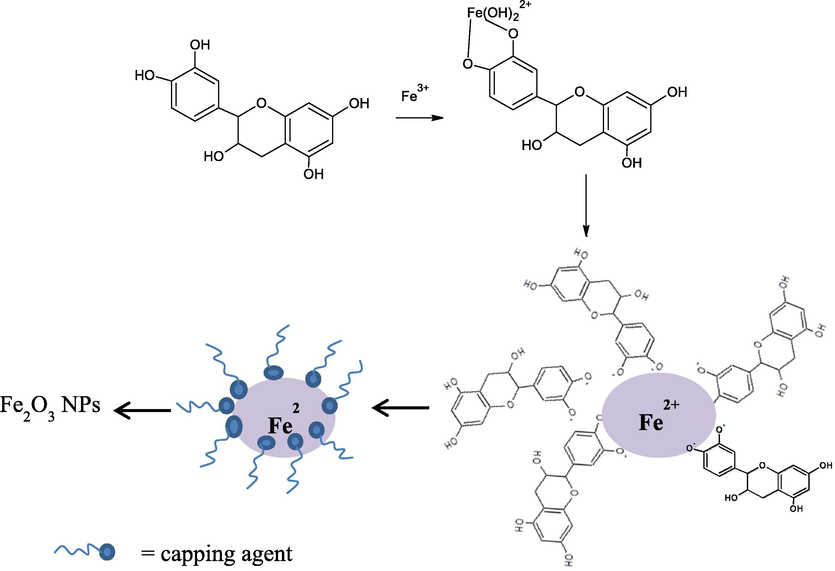
Formation of biosynthesized hematite.
Hydroxyl functional groups in epichatechin molecules will undergo hydrolysis in their anionic form and able to donate electrons. Following reduction mechanism will transform phenolics to their quinone forms allows for the reduction of an iron salt: from Fe3+ to Fe2+ and furthermore form aggregates of Fe2O3 (hematite) (Ahmmad et al., 2013). The success of reduction is demonstrated by the change of solution color and UV–Visible spectra as presented in Fig. 2.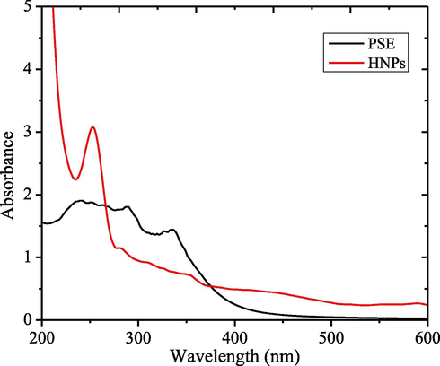
UV–Visible spectra of PSE and HNPs.
The HNPs solution exhibits the intense peak at 320 nm which is the indication of the surface plasmon resonance of iron nanoparticles (Klačanová et al., 2013). Particle size distribution and zeta potential of the synthesized HNPs presented in Fig. 3 imply that the average diameter of nanoparticles are ranging from 20 to 100 nm in size, and the zeta potential is −0.055 mV. The zeta potential which lays on the range of −30 to 30 mV represents the stability of the nanoparticles (Chandrasekar et al., 2013).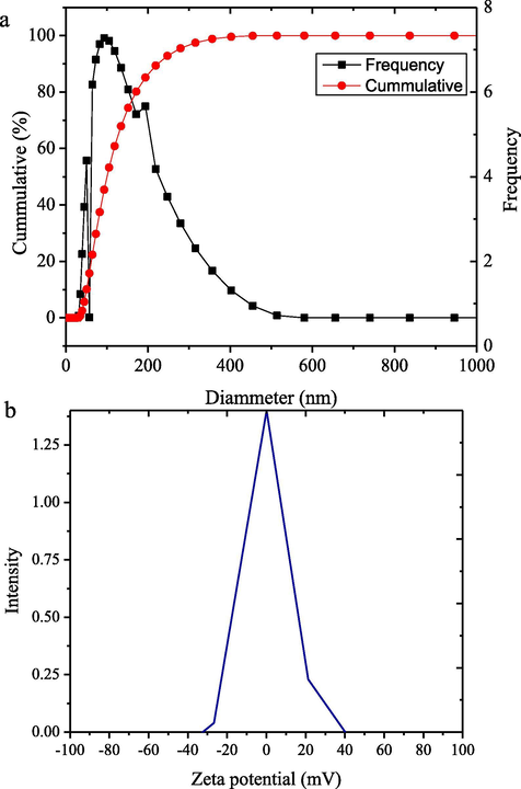
(a) Particle size distribution of HNPs (b) Zeta potential of HNPs.
Fig. 4 displays the XRD patterns of HNPs, HNPs/TUD-1, and TUD-1. As comparison, the reflections of the TUD-1 and HNPs/TUD-1 samples in low angle are also presented. By the large angle, TUD-1 showed a single broad reflection at around 21° as indication of amorphous silica, and at the low angle, it shows a peak at around 0.62° as the indication of a meso-structured material. The attached hematite nanoparticles in the HNPs/TUD-1 structure was identified from some reflections matched with the pattern of HNPs which are located at 24.12, 33.12, 35.61, 40.80, 49.50, 54.00, 56.63, 62.45, and 64.11 which are associated with (1 0 2), (1 0 4), (1 1 0), (1 1 3), (0 2 4), (1 1 6), (2 1 4), and (3 0 0) reflections. These reflection are in confirmation to the standard JCPDS Card no: 79-1741 and similar with was reported by previous green synthesized hematite (Fouad et al., 2019; Rufus et al., 2019).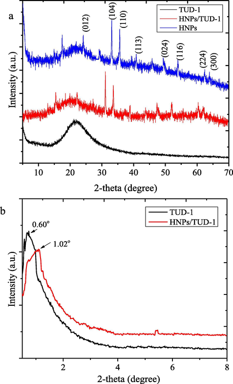
(a) XRD pattern of materials, and (b) Reflection at small angle.
The dispersion affects to the reflection shifts of TUD-1 from 0.60° into higher angle (1.02°) with less intensity and broader peak. This shift represents the lower d-spacing values obtained by hematite dispersion sample. The reflection intensity
slightly decreases with the hematite-loading, indicating an influence of iron oxide-loading on the integrity of the mesoporous structure. Furthermore, the presence of Fe2O3 hematite phase is detected in HNPs/TUD-1 samples as the proof of dispersed form. This pattern is different with the pattern of Fe-nanoparticles dispersed onto TUD-1 reported by Arafat and Bamufleh (2014) which expressed no iron phase reflection in the pattern, as well as the increasing d-spacing by Fe-loading. This difference is due to the higher Si/Fe ratio (8:1) referred to the ratio of SiO2:Fe2O3 = 1:0.25, compared to Si/Fe ranging from 20 to 100 utilized by Arafat and Bamufleh (2014). The dispersed Fe2O3 in this TUD-1 nanostructure may affect to the porous structure as the loading is in the form of metal oxide, instead of Fe nanoparticles. Based on the (1 0 4) and (1 1 0) reflections as dominant peaks in the XRD analysis, the mean crystallite size of dispersed hematite are 38 nm. This assumption is in confirmation with SEM analysis presented in Fig. 5.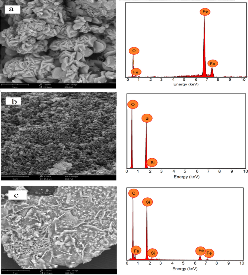
SEM/EDX profile of (a) HNPs (b) TUD-1 (c) HNPs/TUD-1.
Surface profile depicts an evolution of the surface morphology of TUD-1, which seems a sponge-like surface into a flatter and sodden surface in HNPs/TUD-1. The surface appearance of HNPs/TUD-1 is like a combination of a flower-like morphology of HNPs on a silica surface. The elemental analysis results from EDX represents the Si as a major component of TUD-1, and Fe and O as the main components of HNPs, and the Fe content in HNPs/TUD-1 is 3.90% at. corresponding to the Si/Fe molar ratio of 8.25, slightly higher than the set up ratio (Table 1). The SEM images are in consistence with TEM images visualizing this HNPs and silica combination (Fig. 6). The TEM profile of TUD-1 is similar with other previous report on TUD-1 synthesis where the mesoporous sponge-like structures is confirmed with image from HTEM analysis of HNPs/TUD-1 (Fig. 6d) and similar synthesized TUD-1 from other work(Mandal et al., 2014). It can be also noted that, the mesoporous sponge structure becomes less visible in HNPs/TUD-1 sample due to the insertion of HNPs in the structure. As describe by particle size distribution as inset figures in Fig. 6b and c, quantitatively, the particle size of HNPs in the HNPs/TUD-1 is in the size range of 10–80 nm, and less than the particle size of as prepared HNPs (10–120 nm). which is also meet with the particle size distribution measurement (Fig. 3a). The HRTEM image presented in Fig. 6d represents the small size of HNPs deposited on the TUD-1 structure. The smaller particle size in HNPs/TUD-1 is related with the calcination process after hematite attachment by sol-gel formation with TUD-1. This effect is similar with was reported on effect of calcination temperature to the hematite particle size (Nurhayati et al., 2013).
Element
Content (% at.) in
TUD
HNPs
HNPs/TUD-1
O
67.97
52.02
55.19
Si
32.03
0.01
39.61
Fe
nd
47.97
4.80
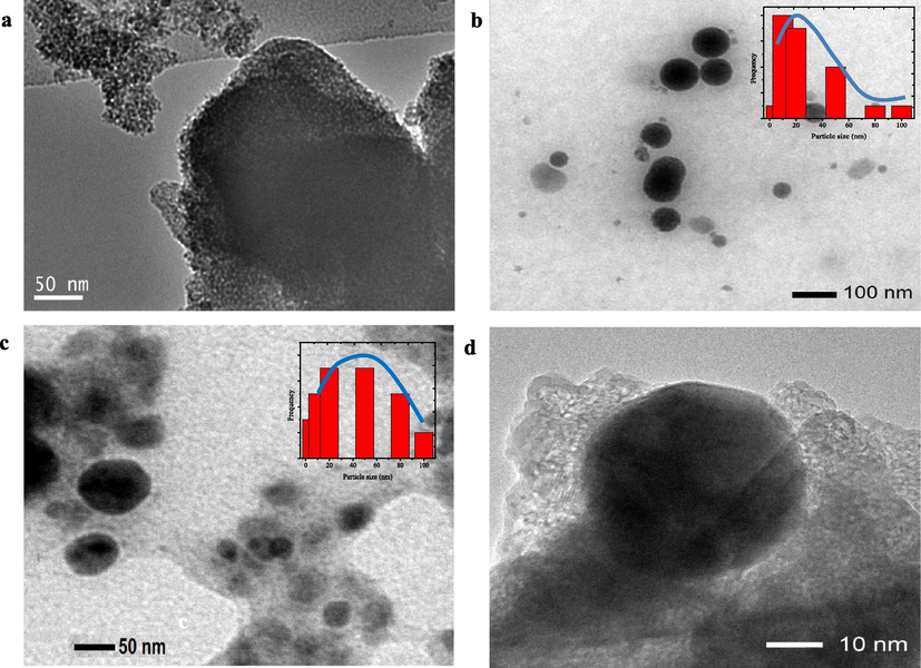
TEM images of (a) TUD-1 (b) HNPs (c) HNPs/TUD-1 (d) HNPs/YUD-1 (HRTEM).
The presence of iron oxide in the composite is also confirmed by XPS analysis presented in Fig. 7. The XPS survey spectrum demonstrates the corresponding signals of Si, O, and Fe as the main elements of the composite (Fig. 7a). XPS spectrum represents the silica network of TUD-1 by the characteristic XPS peaks of silicon (Si) of SiO2 such as Si 2p and Si 2 s states found at 103.6 eV at 154.6 eV, respectively. The peaks at 709 and 725 eV are attributed to the Fe 2p3/2 and Fe 2p1/2 core level signals, respectively (Fig. 7c). Furthermore, the existence of interaction among Fe and TUD-1 is identified by O 1 s spectrum. The observed peak at 532.9 eV is corresponding to the outer silica surface (Si-O-Si bonds) and another at 533.5 eV is attributed due to the adsorbed water, SiOH2+ which refer to XPS analysis of TUD-1 and metal-subtituted TUD-1 (Mandal et al., 2014; Ye et al., 2019).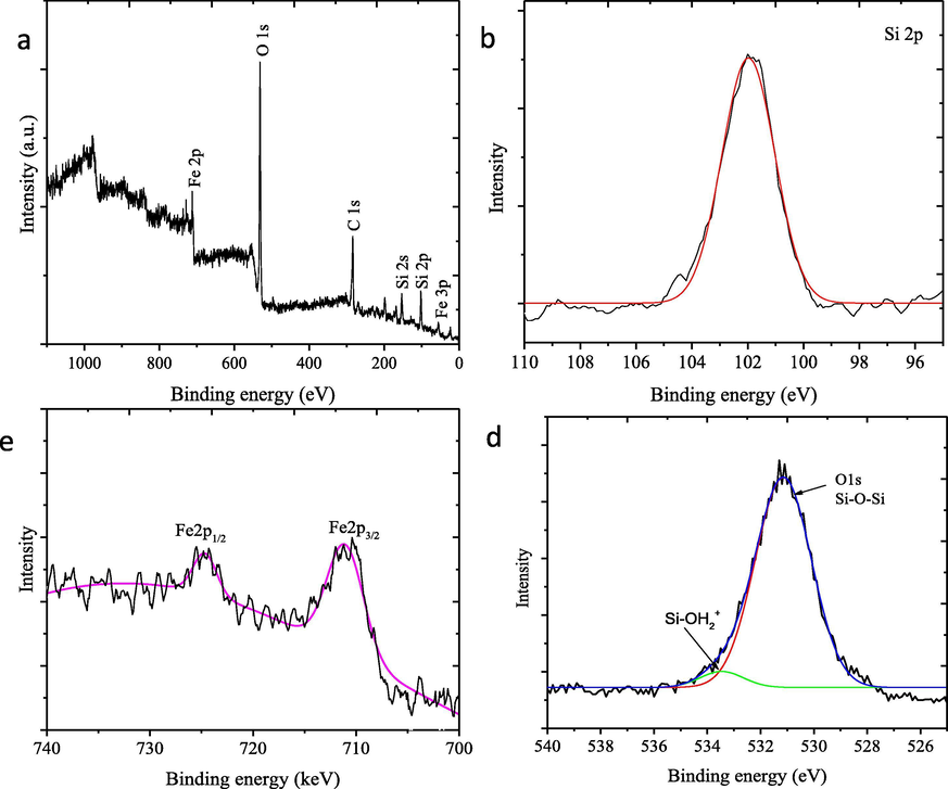
XPS spectra of the (a) survey scan, (b) Si 2p (c) Fe 2p, and (c) O 1s peaks of HNPs/TUD-1.
Fig. 8a presents the nitrogen adsorption isotherms of the samples. The mesoporous structural properties such as the BET surface area, the mesopore volume and the mesopore diameter, derived from the nitrogen physisorption isotherms are given in Table 2. TUD-1 and HNPs/TUD-1 show type IV adsorption isotherms implies the meso-structured character of the solid, meanwhile HNPs represents the microporous material. It is also seen that the dispersion of HNPs onto TUD-1 leads to change in adsorption-desorption profile, especially reducing adsorption capacity along P/Po as indication of less porous structure. This is also accompanied by decreasing the BET surface area, mesopore volume and the mesopore diameter. Moreover, the pore size distribution (Fig. 8b) data suggests that HMNPs clusters are present in the mesopore structure.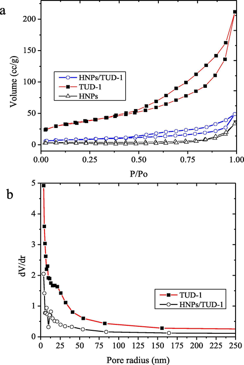
(a) Adsorption-desorption isotherm of materials (b) Pore size distribution of materials.
Parameter
TUD-1
HNPs/TUD-1
HNPs
SBET (m2/g)
588.91
282.45
39.39
External surface area
129.44
78.56
11.12
Mesopore volume (cc/g)
0.63
0.12
0.02
Mesopore diameter (nm)
36.22
21.45
4.20
The capability of attached iron oxide nanoparticles into the mesoporous matrix of TUD-1 to absorb photon for photocatalysis application is further investigated using UV-DRS analysis. The spectra of HNPs/TUD-1 compared to HNPs are presented in Fig. 9. It is seen that both HNPs/TUD-1 and HNPs show the capability to absorb light at 200–525 nm region. Compared to HNPs, HNPs/TUD-1 shows the less absorbance at this region, and also shows the blue shift for the edge wavelength. The optical band gap (Eg) was determined by plotting photon energy (hν) versus (αhν)2 curve following Kubelka-Munk theory. The band gap energy was calculated using following formula (eq.2):
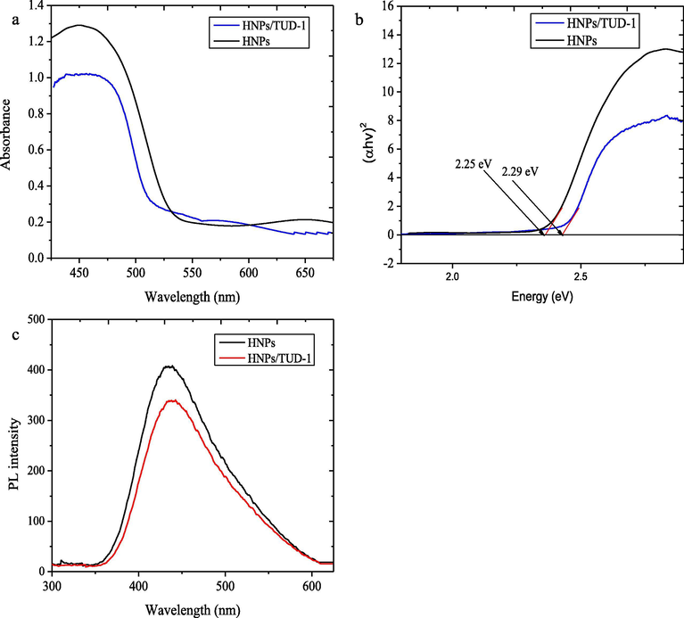
(a) Diffused reflectance UV–Visible spectra (b) (αhν)2 vs hν plot Tauc plot, and (c) PL spectra of of HNPs and HNPs/TUD-1.
Photoluminescence (PL) spectra in Fig. 9c were recorded to examine the electronic interactions between HNPs and TUD-1. The slightly shift of the peak reveals the interaction between the excited state of HNPs and TUD-1, which associated with photo-induced electrons transfer to TUD-1. Furthermore, the peak intensity of PL spectra represents the recombination rate of electron–hole pairs which the lower intensity of the catalyst indicates the lower recombination rate, and theoretically leads to the higher photocatalytic activity (Deng et al., 2017; Eskandari et al., 2019).
3.2 Photocatalytic activity test
Photocatalytic activity of materials was evaluated by degrading bromo phenol blue and methyl violet under UV light irradiation. Since the photocatalysts are impinged with the photon, the excitation of the electron in valence band into conductance band of hematite electronic structure will be occurred and leads to the formation of hole in the valence band. The interactions among electrons and holes with solvent (H2O) and O2 will undergo the hydroxyl radicals and super radicals for oxidation mechanism of dyes. Moreover, these steps in the photocatalytic treatment convert the dyes completely in to harmless end products like carbon dioxide and water. The dye degradation over the treatment can be seen by the change in UV–Vis spectra from initial and treated solution (Fig. 10). The UV–vis spectra of BPB and MV show a strong absorption band at 586 and 660 nm respectively. Both BPB and MV absorption peaks were gradually decreased as a function of UV irradiation time, which was due to breakdown of the chromophoric group in the dye structures. The occurrence of degradation mechanism is confirmed by the kinetics plots and comparison on kinetics constants (Fig. 11) showing the faster decolorization over photocatalytic treatment compared to adsorption treatment (without UV exposure).![UV–Vis spectral changes on photocatalytic degradation of (a) BPB using HNPs/TUD-1 (b) HNPs (c) MV using HNPs/TUD-1 (d) MV using HNPs [ Initial concentration of dye = 30 mg/L, catalyst dose = 0.2 g/500 mL; Ads = adsorption experiment]](/content/184/2020/13/11/img/10.1016_j.arabjc.2020.05.032-fig10.png)
UV–Vis spectral changes on photocatalytic degradation of (a) BPB using HNPs/TUD-1 (b) HNPs (c) MV using HNPs/TUD-1 (d) MV using HNPs [ Initial concentration of dye = 30 mg/L, catalyst dose = 0.2 g/500 mL; Ads = adsorption experiment]
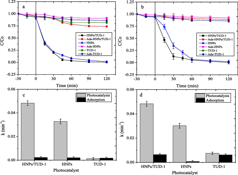
Kinetics plot of photocatalytic degradation and adsorption of (a) BPB (b) MV; Compared kinetics constant of photocatalysis and adsorption of (c) BPB (d) MV.
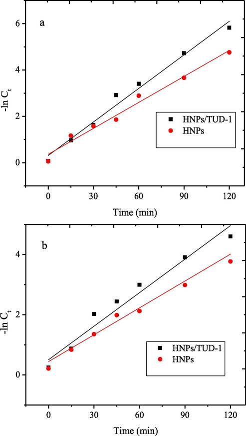
From the kinetics plot of dye degradations, the data was subjected to first-order-kinetics with following equation (3):
First-order kinetics plot of photocatalytic degradation of (a) BPB (b) MV.
Photocatalyst
BPB
MV
Kinetics equation
R2
k (min−1)
Kinetics equation
R2
k (min−1)
HNPs/TUD-1
ln Ct = −0.048 t−0.24
0.9926
0.048
ln Ct = −0.029 t−0.64
0.9765
0.029
HNPs
ln Ct = −0.038 t−0.24
0.9867
0.038
ln Ct = −0.031 t−0.62
0.9563
0.031
The plots and kinetic constant values of the adsorption process over TUD-1 and HNPs/TUD-1 imply the insignificant difference of adsorption capability among the both materials, which mainly correlated with the similar specific surface area. In addition, the kinetics constant of adsorption over HNPs represents its lowest adsorption capability, which the value is also slightly similar with the values from photocatalytic treatment. The data clarifies the role of TUD-1 as porous solid support for attracting dye molecule as part of the photocatalytic mechanism. Quantitatively, the kinetics values of photocatalytic treatment over HNPs/TUD-1 are about 8-fold to the values of adsorption treatment, meanwhile the ratio obtained by HNPs are about 4-fold.
It is also noticeable that the plot of kinetics over HNPs/TUD-1 shows slightly higher initial rate compared to HNPs for both dyes degradation, as also represented by the kinetics constant values. Even though, the DE at degradation time of 90 min seems insignificantly different, and similarly with the TOC values (Fig. 13). Both HNPs/TUD-1 and HNPs express the less TOC removal respect to DE which indicate the availability of degradation products that could not be represented by decolorization.![DE and TOC of photocatalytic degradation (b) Comparison on TON of dye photocatalytic degradation over HNPs and HNPs/TUD-1 [Dye initial concentration = 30 mg/L; photocatalyst dosage = 0.5 g/L; time of treatment = 60 min]](/content/184/2020/13/11/img/10.1016_j.arabjc.2020.05.032-fig13.png)
DE and TOC of photocatalytic degradation (b) Comparison on TON of dye photocatalytic degradation over HNPs and HNPs/TUD-1 [Dye initial concentration = 30 mg/L; photocatalyst dosage = 0.5 g/L; time of treatment = 60 min]
The effectiveness of photocatalysts was measured refer to the turn over number (TON) with following formula: where [DE]90 is degradation efficiency measured at 90 min, and Fe2O3 is percentage of Fe2O3 in the photocatalyst. Refer to Fe content data in Table 3, the calculated mass weight percentage of Fe2O3 for HNPs and HNPs/TUD-1 are 100% and 15%, respectively. TON values represent the quantitative contribution of HNPs as photoactive material is presented in Fig. 13b. The values suggest that the dispersed HNPs on TUD-1 support remarkably on the degradation efficiency since the TON values for BPB degradation are increased from about 0.96 over HNPs to be 6.9 over HNPs/TUD-1, meanwhile for MV are from 0.95 to be 6.5 by using HNPs and HNPs/TUD-1, respectively.
Furthermore, from the kinetics plot, it is seen that the rate of BPB degradation is faster than MV. The most possible reason for this is that BPB contains hydroxyl functional groups in the structure which easily interact with radicals formed by the semiconductor photocatalyst, meanwhile, MV consist of amide (+NH2) which less reactive to the radicals.
This assumption is also in line with the results from LCMS analysis (Fig. 14 and Fig. 15). BPB was observed to be degraded refer to the disappearance of the chromatogram peaks of BPB at 120 min treatment. MS analysis analyses revealed the degradation products to the simpler molecules with m/z 266, 157, 126, 110, 94, 84, and 70. From these results, degradation mechanism of BPB can be predicted on the scheme presented in Fig. 16 (Fatimah et al., 2020; Nezamzadeh-Ejhieh and Zabihi-Mobarakeh, 2014). Similarly, the MV degradation pathway was observed due to the ES+ peaks from MS analysis (Fig. 14) which present m/z of 372, 356, 245, 237, 223, 150. From these facts of spectra, degradation mechanism is predicted to be similar with was reported by Ju et al., (2011). The mechanism suggests that degradation is initiated by de-methylation, which is in line with UV–Visible spectra (inset in Fig. 8c). The reduced absorbance along with the blue shift of the peak is coming from de-methylation (Nezamzadeh-Ejhieh and Zabihi-Mobarakeh, 2014).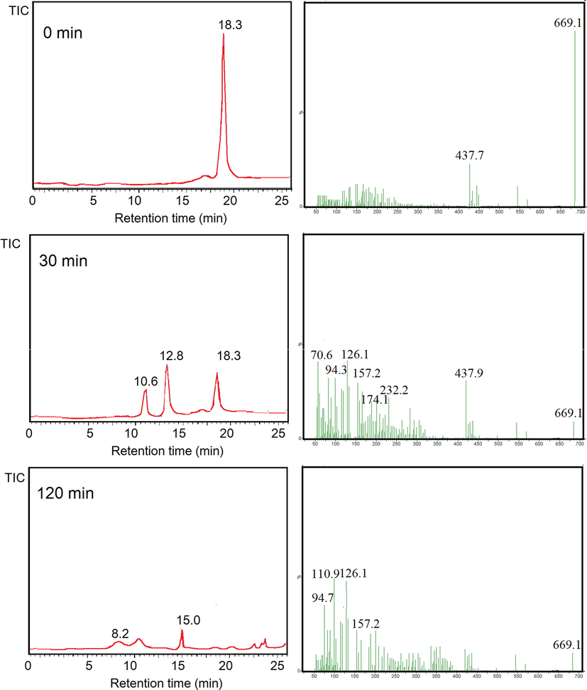
LCMS analysis results from photocatalytic degradation of BPB.
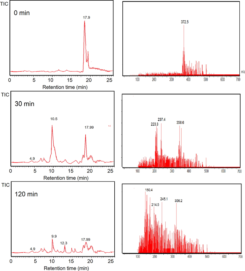
LCMS analysis results from photocatalytic degradation of MV.
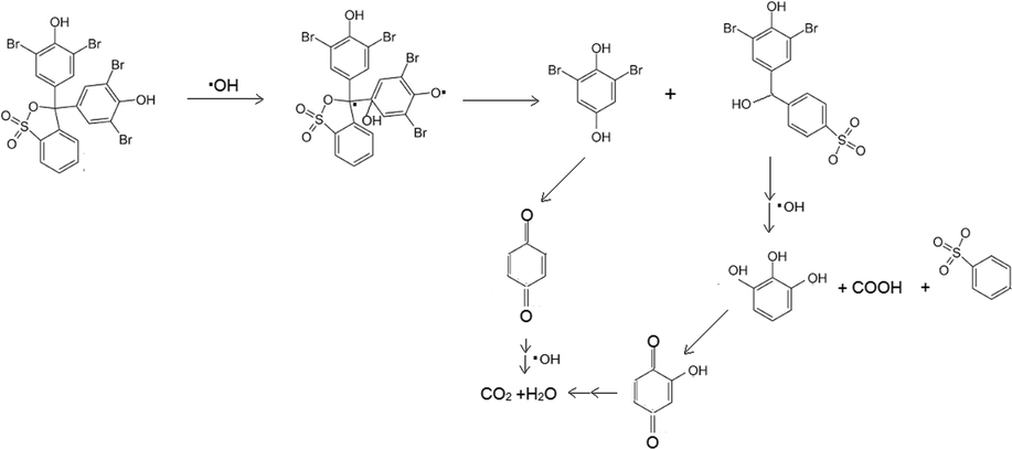
Degradation mechanism of BPB.
The higher degradation rate of BPB compared to MV is in line with the photooxidation kinetics of BPB in comparison with crystal violet (CV) and eosin yellow (EY) over pure ZnO and AgBr-ZnO. The kinetics constant and degradation efficiency of BPB photooxidation is higher than CV, but lower than EY (Abdel-Khalek et al., 2018). The structure of EY and BPB contain hydroxyl, moreover EY has carboxyl and ketone functional groups. Meanwhile CV is azo dye with no both functional groups. The higher degradation rate of dye structure is related with the possible propagation steps which involve the ring opening accelerate by the higher affinity towards radicals. The radical prefers to attack structure with presence of OH carbonyl (—COOH) in the structure(Abdel-Khalek et al., 2018; Hisaindee et al., 2013).
Comparison of photocatalytic activity of HNPs/TUD-1 with other photocatalysts materials is listed in Table 4. What can be concluded from the comparison is that HNPs/TUD-1 prepared in this work has comparable activity for BPB and MV dyes.
Photocatalyst
DE (%)*
remark
reference
TiO2/Pd
100
Photocatalyst dose = 0.02 g/10 mL, [MV]0 = 15 mg/L, irradiation time = 20 min, UV lamp = 254 nm, 15 W
(Saeed et al., 2017)
AC-Bi/ZnO
95
Photocatalyst dose = 0.08 g/40 mL, [MV]0 = 2 × 10⁻³ M, irradiation time = 60 min, UV lamp = 254 nm, 15 W
(Chandraboss et al., 2015)
ZnO nanorod
74
Photocatalyst dose = 0.03 g/100 mL, [MV]0 = 10 mg/L.
(Punithavathy et al., 2017)
Graphite/PbTiO3
94
Photocatalyst dose = 0.3 g/30 mL, [MV]0 = 3 mg/L.
(Purnawan et al., 2018)
HNPs/TUD-1
94.6
Photocatalyst dose = 0.2 g/500 mL, [MV]0 = 30 mg/L, irradiation time = 60 min, UV lamp = 254 nm, 15 W
This research
Magnetic nanoparticle
99
Photocatalyst dose = 0.2 g/500 mL, [BPB]0 = 20 mg/L, irradiation time = 60 min, UV lamp = 254 nm, 15 W
(Fatimah et al., 2020)
Graphene nanoplates–supported TiO2
86
Photocatalyst dose = 0.02 g of GNP/TiO2 was added to 10 mL of 100 ppm
(Shah et al., 2019)
TiO2
85.4
Photocatalysis was -mediated by Mo(VI)-peroxo complexes in the presence of SDS, catalyst dose = 0.1 g/500 mL
(Temel et al., 2015)
Graphene nanoplatelets/polypyrrole nanocomposites
93
Photocatalyst dose = 50%
(Noreen et al., 2019)
HNPs/TUD-1
96.7
Catalyst dose = 0.2 g/500 mL, [MV]0 = 30 mg/L, irradiation time = 60 min, UV lamp = 254 nm, 15 W
This research
3.3 Photocatalytic mechanism
The schematic representation of the possible photocatalytic mechanism over HNPs/TUD-1 under of UV light is presented in Fig. 17. Refer to Bledowski et al.,(2011) notified that the redox potential of the CB of Fe2O3 is at around 0.2 eV, and taking into account that the band gap energy of HNPs/TUD-1 is 2.29 eV, so the VB is located at 2.49 eV. The CB has lower redox potential than the formation of superoxide anion radicals (O2•-) [E0 (O2/O2•-) = -0.33 eV. This condition leads to the spontaneously formation of O2•− and HOO•− as there is interaction of excited electrons with O2. Moreover, the VB has higher potential reduction compared to the oxidation of water [E0 (H2O/•OH) = 2.38 V], which accommodates the interaction of the electron hole with H2O to produces HO• (Dong et al., 2020). These generated radicals are the effective oxidants for dye degradation. A further reaction is oxidation releases CO2, H2O, and SO3− upon the completion.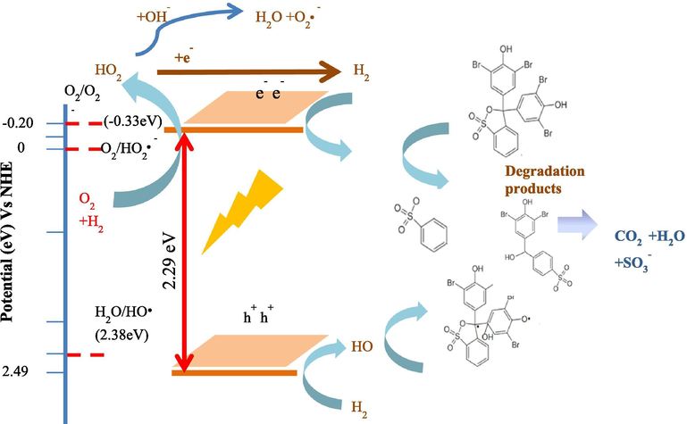
Schematic representation of the photocatalytic mechanism by HNPs/TUD-1.
3.4 Photocatalytic stability
Photocatalyst stability is important parameter in the practical applications. The stability is related with the repeatability of photocatalyst, and the evaluation was conducted by using cyclic experiments. Fig. 18 shows the comparison of kinetic constant of the dye degradation over HNPs and HNPs/TUD-1 for 5 runs of reactions.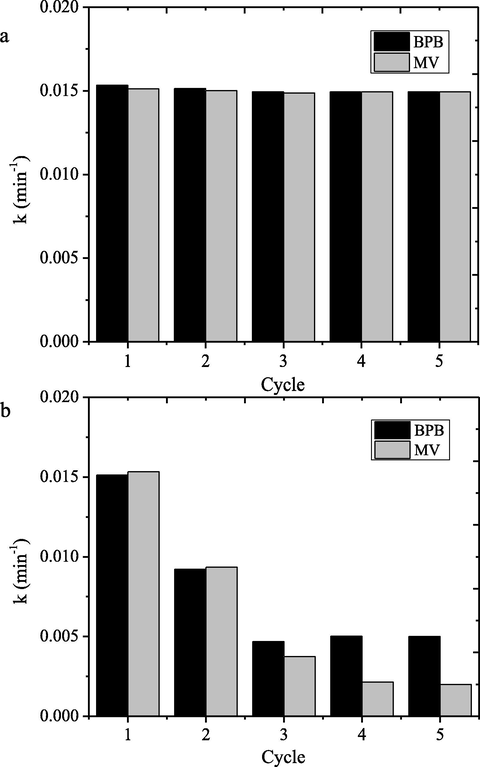
Kinetics constants of dye photocatalytic degradation at cycling runs.
The observed data indicate that photocatalytic activity of HNPs/TUD-1 degradation reaction for both dyes is maintained until 5 cycles, but it is remarkably different for HNPs. The kinetics constants are slightly decreased with the following cycle’s wth the reduction percentage of about 10% respect to first use. Contrarily, the decreasing kinetics constant at usage is clearly recognized for HNPs. The kinetics constant of the second use was reduced until 60% compared to the first use, the significant reduction goes more for further cycles. The higher repeatability is in line with contribution of electron charge process refer to PL spectra, and also participation of adsorption capability of TUD-1. The charge transfer facilitates an efficient recycling of Fe(III)–Fe(II) pairs on the surface of HNPs/TUD-1 thus enhance the photocatalytic degradation efficiency. Meanwhile, the fast photocatalytic activity loss of HNPs is related with the more oxidizable surface, surface blocking by degradation product residue. Similar phenomenon was also reported by comparison on iron oxide nanocomposite with bulk iron nanocomposites (Liu et al., 2017a,b; Pradhan et al., 2011, 2013)].
4 Conclusion
Nanocomposite of hematite/TUD-1 has been successfully synthesized. The material was obtained by biosynthesis of hematite nanoparticles using Parkia speciossa hassk pod as bioreductor followed using sol-gel reaction the hematite with TUD-1 precursor. The nanocomposite represents a mesoporous structured material with the dispersed hematite nanoparticles size ranging from 10 to 50 nm and the band gap energy of 2.29 eV. The nanocomposite exhibits considerable photocatalytic activity as shown by the capability to degrade BPB and MV with the degradation efficiencies of 94.6 and 96.7%, respectively.
Acknowledgment
The authors gratefully acknowledge the financial support from the Kementrian Riset-Badan Riset Nasional, Republic of Indonesia via Hibah Penelitian Unggulan Dasar Perguruan Tinggi 2020, also thank to Bunseki Analysis center of Gifu University for access of XPS analysis.
Declaration of Competing Interest
The authors declare that they have no known competing financial interests or personal relationships that could have appeared to influence the work reported in this paper.
References
- Visible light assisted photocatalytic degradation of crystal violet, bromophenol blue and eosin Y dyes using AgBr-ZnO nanocomposite. Environ. Nanotechnol. Monit. Manage.. 2018;9:164-173.
- [CrossRef] [Google Scholar]
- Green synthesis of mesoporous hematite (α-Fe2O 3) nanoparticles and their photocatalytic activity. Adv. Powder Technol.. 2013;24:160-167.
- [CrossRef] [Google Scholar]
- Green synthesis of α-Fe2O3 nanoparticles for photocatalytic application. J. Mater. Sci.: Mater. Electron.. 2014;25:3572-3577.
- [CrossRef] [Google Scholar]
- Fe2O3/TUD-1: an efficient catalysts for Friedel-Crafts alkylation of aromatics. J. Porous Mater.. 2014;21:1091-1100.
- [CrossRef] [Google Scholar]
- Green route for synthesis hematite (α-Fe2O3) nanoparticles: Toxicity effect on the green peach aphid, Myzus persicae (Sulzer) Environ. Nanotechnol. Monit. Manage.. 2018;9:107-111.
- [CrossRef] [Google Scholar]
- Visible-light photocurrent response of TiO2-polyheptazine hybrids: Evidence for interfacial charge-transfer absorption. PCCP. 2011;13:21511-21519.
- [CrossRef] [Google Scholar]
- An efficient removal of methyl violet from aqueous solution by an AC-Bi/ZnO nanocomposite material. RSC Adv.. 2015;5:25857-25869.
- [CrossRef] [Google Scholar]
- Facile synthesis of iron oxide, iron-cobalt and zero valent iron nanoparticles and evaluation of their anti microbial activity, free radicle scavenginging activity and antioxidant assay. Digest J. Nanomater. Biostruct.. 2013;8:765-775.
- [Google Scholar]
- An advanced TiO2/Fe2TiO5/Fe2O3 triple-heterojunction with enhanced and stable visible-light-driven fenton reaction for the removal of organic pollutants. Appl. Catal. B. 2017;211:157-166.
- [CrossRef] [Google Scholar]
- Construction of morphology-controlled nonmetal 2D/3D homojunction towards enhancing photocatalytic activity and mechanism insight. Appl. Catal. B. 2020;263:118270
- [CrossRef] [Google Scholar]
- Adsorption and Photodegradation Efficiency of TiO2/Fe2O3/PAC and TiO2/Fe2O3/Zeolite Nanophotocatalysts for the Removal of Cyanide. Ind. Eng. Chem. Res.. 2019;58:2099-2112.
- [CrossRef] [Google Scholar]
- Green synthesis of silver nanoparticles using extract of Parkia speciosa Hassk pods assisted by microwave irradiation. J. Adv. Res.. 2016;7:961-969.
- [CrossRef] [Google Scholar]
- Synthesis of magnetic nanoparticles using Parkia speciosa Hassk pod extract and photocatalytic activity for Bromophenol blue degradation. Egypt. J. Aquat. Res.. 2020;1–6
- [CrossRef] [Google Scholar]
- Improved size, morphology and crystallinity of hematite (α-Fe2O3) nanoparticles synthesized via the precipitation route using ferric sulfate precursor. Res. Phys.. 2019;12:1253-1261.
- [CrossRef] [Google Scholar]
- Fe, Co and Cu-incorporated TUD-1: Synthesis, characterization and catalytic performance in N2O decomposition and cyclohexane oxidation. Catal. Today. 2005;110:264-271.
- [CrossRef] [Google Scholar]
- Application of LC-MS to the analysis of advanced oxidation process (AOP) degradation of dye products and reaction mechanisms. TrAC - Trends Analyt. Chem.. 2013;49:31-44.
- [CrossRef] [Google Scholar]
- A Review on the Phytochemicals of Parkia Speciosa, Stinky Beans as Potential Phytomedicine. J. Food Sci. Nutr. Res.. 2019;02:151-173.
- [CrossRef] [Google Scholar]
- Photodegradation of crystal violet in TiO2 suspensions using UV-vis irradiation from two microwave-powered electrodeless discharge lamps (EDL-2): Products, mechanism and feasibility. J. Hazard. Mater.. 2011;185:1489-1498.
- [CrossRef] [Google Scholar]
- Kamisah, Y., Othman, F., Qodriyah, H.M.S., Jaarin, K., 2013. Parkia speciosa Hassk.: A potential phytomedicine. Evidence-based Complement. Alternat. Med. doi:10.1155/2013/709028.
- Formation of Fe(0)-nanoparticles via reduction of Fe(II) compounds by amino acids and their subsequent oxidation to iron oxides. J. Chem. 2013
- [CrossRef] [Google Scholar]
- Fe2O3 photocatalyst supported on ultra-fine fibrous Al2O3 via electroblown spinning (EBS) with an application to organic dye degradation. Mater. Rep.. 2018;32:207-212.
- [Google Scholar]
- Metal-containing TUD-1 mesoporous silicates as versatile solid acid catalysts for the conversion of bio-based compounds into valuable chemicals. Inorg. Chim. Acta. 2015;431:289-296.
- [CrossRef] [Google Scholar]
- Metal nanoparticles induced photocatalysis. Natl. Sci. Rev.. 2017;4:761-780.
- [CrossRef] [Google Scholar]
- Enhanced catalytic degradation of methylene blue by Α-Fe2O3/graphene oxide via heterogeneous photo-Fenton reactions. Appl. Catal. B. 2017;206:642-652.
- [CrossRef] [Google Scholar]
- Enhancement of H2O2 decomposition efficiency by the co-catalytic effect of iron phosphide on the Fenton reaction for the degradation of methylene blue. Appl. Catal. B. 2019;259:118015
- [CrossRef] [Google Scholar]
- XAFS, XPS characterization of cerium promoted Ti-TUD-1 catalyst and it’s activity for styrene oxidation reaction. Catal. Commun.. 2014;46:123-127.
- [CrossRef] [Google Scholar]
- Photocatalytic Water Oxidation by Hematite/Reduced Graphene Oxide Composites. ACS Catal.. 2013;3:746-751.
- [Google Scholar]
- Heterogeneous photodecolorization of mixture of methylene blue and bromophenol blue using CuO-nano-clinoptilolite. J. Ind. Eng. Chem.. 2014;20:1421-1431.
- [CrossRef] [Google Scholar]
- Noreen, H., Iqbal, J., Arshad, A., Faryal, R., Ata-ur-Rahman, Khattak, R., 2019. Sunlight induced catalytic degradation of bromophenol blue and antibacterial performance of graphene nanoplatelets/polypyrrole nanocomposites. J. Solid State Chem. 275, 141–148. doi:10.1016/j.jssc.2019.03.045.
- Nurhayati, T., Iskandar, F., Abdullah, M., Khairurrijal, 2013. Syntheses of hematite (α-Fe2O3) nanoparticles using microwave-assisted calcination method. Mater. Sci. Forum 737, 197–203. doi:10.4028/www.scientific.net/MSF.737.197.
- Mesoporous nanocomposite Fe/Al2O3-MCM-41: An efficient photocatalyst for hydrogen production under visible light. Int. J. Hydrogen Energy. 2011;36:12753-12760.
- [CrossRef] [Google Scholar]
- Fabrication of #-Fe2O3 Nanorod/RGO composite: A novel hybrid photocatalyst for phenol degradation. ACS Appl. Mater. Interfaces Appl. Mater. Interface. 2013;5:9101-9110.
- [CrossRef] [Google Scholar]
- Photodegradation of methyl violet dye using ZnO nanorods. J. Mater. Sci.: Mater. Electron.. 2017;28:2494-2501.
- [CrossRef] [Google Scholar]
- Methyl violet degradation using photocatalytic and photoelectrocatalytic processes over graphite/PbTiO3composite. Bull. Chem. React. Eng. Catal.. 2018;13:127-135.
- [CrossRef] [Google Scholar]
- Size tunable biosynthesis and luminescence quenching of nanostructured hematite (α-Fe2O3) for catalytic degradation of organic pollutants. J. Phys. Chem. Solids. 2019;124:221-234.
- [CrossRef] [Google Scholar]
- Efficient photodegradation of methyl violet dye using TiO2/Pt and TiO2/Pd photocatalysts. Appl. Water Sci.. 2017;7:3841-3848.
- [CrossRef] [Google Scholar]
- Transition metal/metal oxide modified MCM-41 for pollutant degradation and hydrogen energy production: A review. RSC Adv.. 2015;5:83707-83724.
- [CrossRef] [Google Scholar]
- Saif, S., Tahir, A., Chen, Y., 2016. Green Synthesis of Iron Nanoparticles and Their Environmental Applications and Implications 1–26. doi:10.3390/nano6110209
- Photodegradation of bromophenol blue in aqueous medium using graphene nanoplates-supported TiO2. Appl. Water Sci.. 2019;9:1-7.
- [CrossRef] [Google Scholar]
- TUD-1: Synthesis and application of a versatile catalyst, carrier, material. J. Mater. Chem.. 2010;20:642-658.
- [CrossRef] [Google Scholar]
- Temel, N.K., Gürkan, R., Ayan, F., 2015. Photocatalytic TiO 2 -catalyzed degradation of bromophenol blue-mediated Mo (VI) -peroxo complexes in the presence of SDS 3994. doi:10.1080/19443994.2015.1111813
- Recent developments of metal oxide based heterostructures for photocatalytic applications towards environmental remediation. J. Solid State Chem.. 2018;267:35-52.
- [CrossRef] [Google Scholar]
- Post Synthesis of aluminum modified mesoporous TUD-1 materials and their application for FCC diesel hydrodesulfurization catalysts. Catalysts. 2017;7:1-20.
- [CrossRef] [Google Scholar]
- Textile dye wastewater characteristics and constituents of synthetic effluents: a critical review. Int. J. Environ. Sci. Technol.. 2019;16(2):1193-1226.
- [CrossRef] [Google Scholar]
- An ultrathin carbon layer activated CeO2 heterojunction nanorods for photocatalytic degradation of organic pollutants. Appl. Catal. B. 2019;259
- [CrossRef] [Google Scholar]


