

Translate this page into:
Highly efficient adsorbent for the transformer oil purification by ZnO/Graphene composite
⁎Corresponding author. tan.vuthi@hust.edu.vn (T. Tan Vu)
-
Received: ,
Accepted: ,
This article was originally published by Elsevier and was migrated to Scientific Scholar after the change of Publisher.
Peer review under responsibility of King Saud University.
Abstract
In this work, a highly efficient adsorbent consisting of the ZnO/Graphene composite was prepared for the first time via the sonification route using urea as an alkaline precursor. The synthesized ZnO/Graphene composite provides the highest specific surface area comparing to other ZnO/Graphene composites synthesized by different approaches presented in the literature. For all we know, this is the first time the obtained ZnO/Graphene composite was used as an adsorbent for the transformer oil purification. The results showed that the ZnO/Graphene composite has a higher purification capacity than the conventional adsorbent, a commercial zeolite. Several factors that may underpin this outstanding result, such as the unreduced oxygen functional groups, the vacancy defects on the surface of the RGO flake, the high specific surface area, and the suitable pore size of the ZnO/Graphene composite for oil refining. Besides, the 3D structure of the ZnO/Graphene composite can enlarge the residence purification time of the transformer oil, helping to improve the purification capacity of the ZnO/Graphene composite.
Keywords
Adsorbent
ZnO/Graphene composite
Transformer oil
Purification

1 Introduction
Transformer oil is an indispensable part of a high-voltage transformer because it provides reliable isolations and removing heat from the hot parts. However, the hydrocarbons in the oil can be degraded by several factors such as high working temperature (70–80 °C), the entrance of atmospheric moisture, and the presence of metallic compounds such as iron, copper, and lead. This degradation is the principle of reducing oil insulating properties in the transformer (Rafiq et al., 2016; Safiddine et al., 2019).
The mechanism of the degradation of the transformer oil is resumed in Fig. 1:
-
–
The degradation process starts with the formation of the hydrocarbon radical (R•)
-
–
The hydrocarbon radical (R•) reacts with oxygen in the air to form peroxy radicals (RO2•)
-
–
The hydroperoxide (ROOH) is formed from the reaction between the peroxy radical (RO2•) and the hydrocarbon molecules.
-
–
Ketones, alcohols, aldehyde, and organic acids are formed from the degeneration of the hydroperoxides. In addition, organic acids can form esters and resin. Therefore, after the oxidation process, the oil acidity will increase, and several products such as sludges, and oil coagulating are created (HodgesBSc and Pet., 1996).
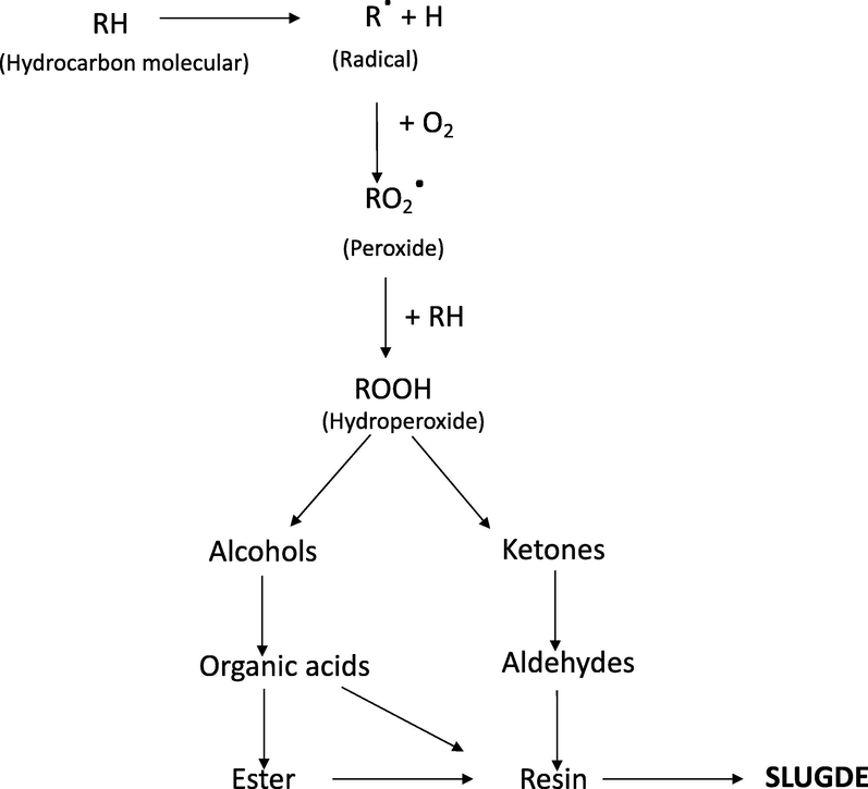
- Mechanism of the formation of sludge in the transformer oil (Hydraulic Fluids − 1st Edition, s. f.)
It is well to know that the generated sludge may accumulate on the transformer surface, avoiding oil circulation and reducing oil dielectric strength. Therefore, the sludge may cause failure in the power transformer during its working time. Additionally, the acidic provokes corrosion of the metal surface in the transformer. And the water generated in oil might reduce the oil dielectric strength (Liu et al., 2019; Salvi & Paranjape, 2017). Consequently, it is necessary to purify the aged oil in the transformer to eliminate formed sludges, water, and regular acidic degrees in the oil transformer.
Recently, adsorbent materials are the best candidate to use for the purification of transformer oils. Many adsorbents are widely used for the oil purification, such as activated bauxite (Oumert et al., 2017), microparticles of carbonated calcium phosphate (CACP)- biopolymers of chitosan polysaccharide (Laurentino et al., 2007), activated carbon (Sulaiman et al., 2011), zeolite (Fofana et al., 2004) and Kaolin clay (Hafez et al., 2015). However, the use of the mentioned adsorbent materials still has some drawbacks. The use of bauxite minerals can generate a large volume of waste (Oumert et al., 2017). High generation cost is the main disadvantage of biopolymers in oil purification (Laurentino et al., 2007). Microparticles of CACP are not considered an optimum adsorbent due to their low specific surface area (Laurentino et al., 2007). In recent times, metallic oxides, zeolite compounds are intensively employed to eliminate unwanted pollutants in the aged transformer oil (Oumert et al., 2017).
In recent times, reduced graphene oxide (RGO) is an excellent adsorbent material for wastewater treatments due to its high adsorption capacity (Ali & Sandhya, 2014; Minitha et al., 2017; Gupta & Khatri, 2017; Ramesha et al., 2011). The unique surface adsorption properties of RGO flake make the adsorption process faster than other materials (Xiao et al., 2016). Additionally, its unreduced oxygen functional groups and vacancy defects on the surface provide a high adsorption capacity. The large specific surface area is also the main reason to make RGO becoming an outstanding adsorbent (Vinh et al., 2019).
The combination of RGO and metal oxide composites, for example, ZnO/RGO composite, has been widely studied as adsorbents (Seredych et al., 2012a, 2012b; Seredych & Bandosz, 2011). The presence of several oxygen groups on the surface of RGO helps it make bonds with active metal oxide parts. Thus, those oxygen functional groups may change the active sites on the surface of adsorbents and their chemical heterogeneity making the RGO/metal oxides composite become a superior adsorbent (Seredych et al., 2012a). Among several RGO/metal oxide composites, the ZnO/Graphene composite gains much attention. The ZnO/Graphene composite is widely used for several applications such as photodetector (Zhu et al., 2018), photocatalyst (Durmus et al., 2019), or adsorbent for wastewater decontamination (Wu et al., 2019, p. 2). However, to the best of our knowledge, ZnO/RGO composite is not recently used to purify aged oil. Significantly, the purification of the aged transformer oil is a new application field for this composite.
According to the literature, numerous methodologies for the fabrication of ZnO/Graphene composite have been reported, such as solvothermal (Atchudan et al., 2016), chemical vapor deposition (Liu et al., 2018), electrochemical (Hao et al., 2018), hydrothermal (Ding et al., 2015). In most of the synthesis method, graphene was prepared separately before the ZnO/Graphene composite fabrication. Those synthesises always imply using Zn salts and hazardous reducing compounds, such as hydrazine and NaBH4 for GO reduction (Kumar et al., 2015). The other moderate synthesis approaches require different solvents or microwave energy under temperature or pressure (Guo et al., 2016). Consequently, it is essential to develop a green, scalable, and economical route to fabricate ZnO/Graphene composite to meet the advanced applications for this material.
The sonification route is a promising alternative approach for obtaining composite nanoparticles (Sebastian et al., 2019). Base on the theoretical, ZnO nanoparticles can be easily synthesized using the sonication method under alkaline conditions (Noman et al., 2019). The GO can also be reduced to RGO under alkaline conditions, such as urea (Vinh et al., 2019). Therefore, in this work, we combined the reduction of GO with the synthesis of ZnO nanoparticles in only one step using the sonification route. This approach weighs over reported literature methodology, as no toxic reducing agents, temperature, or pressure are used.
The synthesized material in this work was denoted as ZnO/Graphene composite and purified aged transformer oil for the first time. The ZnO/Graphene composite's purification capacity was compared with zeolite ZSM-5, a commercial zeolite, an aluminosilicate zeolite belonging to the pentasil family of zeolites. Recently, this zeolite is widely used in purification and separation purposes.
2 Experimental details
2.1 The preparation of Graphene Oxide
For the ZnO/Graphene composite preparation, Graphene Oxide (GO) was prepared using Graphite flake as a raw material via the modified Hummer method (Vinh et al., 2019). The lateral size of the Graphite flake is in the range from 50 to 100 µm.
20 g of Graphite and 20 g of sodium nitrate were mixed by mechanical agitation with 500 mL of 98 wt% sulfuric acid. The mixture was placed in an ice-bath to low down the temperature until 5 °C. At that point, 70 g of potassium permanganate was gradually added into the cooled mixture. It is very vital to keep the mixture temperature below 50 °C during the addition of potassium permanganate.
After adding potassium permanganate, the reaction mixture was treated at 40 °C for 5 h for a complete oxidation process. Then, 200 mL of demineralized water was poured into the mix to stop the reaction. Consequently, 10–15 mL of H2O2 (30 wt% in water) was introduced to remove the rest of the potassium permanganates. At this moment, the reaction mix was turned to a light-yellow color. Subsequently, 100 mL of HCl 20% was added to eliminate the manganese oxide formed during the oxidation reaction. Finally, the Graphite oxide with bright yellow color was obtained. The synthesized material was dried at 40 °C in the oven for three days to obtain dried powder Graphite Oxide.
The GO dispersion was obtained by exfoliating Graphite Oxide in demineralized water using ultrasonic equipment 750 W. The unexfoliated Graphite Oxide was separated by a centrifugation step at 3000 rpm for 10 min. The concentration of the GO dispersion was adjusted to 2 g/L.
2.2 The preparation of ZnO/Graphene composite
In this work, the single step of the fabrication of ZnO/Graphene composite is a combination of two processes: the formation of ZnO nanoparticles by the reaction of zinc salt precursor and urea (Tan et al., 2019) and the reduction of GO by urea (Vinh et al., 2019). Urea was employed for the precipitation of ZnO nanoparticles, and at the same time, urea acts as a reducing agent of GO. A typical mixture of 2.19 g of Zn(CH3COO)2·7H2O, 6 g urea, and 300 mL dispersion of GO of 2 g/L was ultrasonicated in an ultrasonic bath 100 W. The prepared mixture then was sonicated at 80 °C for 5 h. After that, the obtained solid was collected by vacuum filtering and washing with an abundant amount of demineralized water. Finally, the obtained solid was dried in the oven at 60 °C for one day. The sample was designated as ZnO/Graphene composite.
2.3 Treatment process
In this study, transformer oils (in service for five years) were collected from the sub-station located in HABAC NITROGENOUS FERTILIZER & CHEMICALS COMPANY LIMITED were used. The oil was taken from a 10 MVA, 30/10 kV power transformer.
The experiment was performed at room temperature. A typical mixture consists of 2 g ZnO/Graphene composite was mixed with several volumes of aged oil: 50 mL, 100 mL, 150 mL. The mix of aged oil and ZnO/Graphene composite was mechanically stirred for 1 h. After that, the ZnO/Graphene composite was separated from the aged oil by the decantation process. The treated oils were denoted as G-oil-50; G-oil- 100; G-oil-150, according to the used volume of oils.
The purifying capacity of the as-prepared ZnO/Graphene composite was compared with the conventional material, zeolite ZSM5. This material was purchased from Alfa Aesar, under the commercial name Alfa Aesar™ Zeolite ZSM-5. The molar ratio between SiO2 and Al2O3 is 30:1 with a specific surface area of 364 m2/g.
A 2 g of a zeolite ZSM-5, commercial zeolite, was used to treat several volumes of aged oil: 50 mL, 100 mL, 150 mL. The treated samples were denoted as Z-oil-50; Z-oil- 100; Z-oil-150, according to the used volume of oils.
2.4 Characterization of the ZnO/Graphene composite
The X-ray diffraction (XRD) spectra were analyzed by a Bruker D8 Advance instrument operating at 40 kV and 40 mA using Cu Kα radiation (λ = 0.15406 nm). The crystal size values were calculated from the XRD pattern by using Scherrer’s equation (dXRD). The samplés morphology was examined by scanning electron microscopy (SEM, FEI Quanta FEG 650 model). Transmission electron microscopy (TEM, JEOL- JEM 1010 Microscope 300 kV). The instrumental contribution to line broadening was taken into account. The Raman analysis was recorded on a micro-Raman spectrophotometer (JASCO Raman NRS-3000) using a 633 nm excited laser at room temperature. The ZnO/Graphene composite's elemental composition was examined by means of LECO CHN-2000 and FRX spectroscopy (SRS 3000 Bruker).
All the N2 isotherm results were obtained on a Micromeritics ASAP 2020 analyzer. The Brunauer–Emmett–Teller (BET) equation was employed to estimate the ZnO/Graphene composite's specific surface area. The degasification was carried out at 150 °C and established under vacuum condition for 10 h before measurement. The BET results were determined by the amount of adsorbed versus relative pressure (P/P0 from 0 to 0.30). The total pore volume (Vp) and pore size distribution were determined at P/P0 = 0.98 using N2 adsorption isotherms (77 K) by using the Barrett-Joyner-Halenda (BJH) model.
2.5 Characterization of the treated oil
The characterization of the treated oil was measured following the International Electrotechnical Commission (IEC) and the International Organization for Standardization (ISO) standard specifications. The following techniques were used for the characterization of oils:
-
The breakdown voltage was measured by the KEP OLT-80A tester.
-
The acidity index was measured by using Burette TITRETTE. The amount of acid presented in the oil was determined by the number of mg potassium hydroxide (KOH) used to neutralize 1 g of aged oil. Phenolptaline was used as an indicator to control the endpoint of the titration.
-
The oil color was measured by Spectrophotometric Colorimeters OKATON C-105.
-
The viscosity was measured by Ostwald’s viscometer.
3 Results and discussion
3.1 Characterization of the ZnO/Graphene composite
3.1.1 Scanning Electron Microscope (SEM) analysis
SEM technique was used to study the general morphology of the ZnO/Graphene composite. Fig. 2 shows the typical high-resolution SEM images of the Graphene Oxide (GO) flake (Fig. 2a and b), and the as-prepared ZnO/Graphene composite (Fig. 2c and d). It can be observed that the GO consists of a transparent layer and flat flake structure before the formation of the ZnO/Graphene composite. Fig. 2c and d display that the ZnO nanoparticles are homogeneously distributed on the surface of the RGO. The ZnO/Graphene composite's wrinkle assembly shows that GO was wholly converted into RGO with a 3D structure.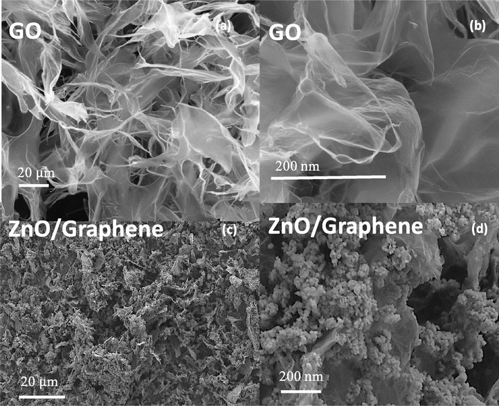
The high resolution of SEM images of Graphene Oxide (a) and (b); ZnO/Graphene composite (c) and (d).
3.1.2 Transmission electron microscopy analysis
The TEM image is an essential tool for the comprehensive observation of the particle size and its distribution. At low-resolution TEM images, both material GO and the ZnO/Graphene composite present a characteristic 2D structure with the lateral size around 10 µm (Fig. 3a and d). The high-resolution TEM image of Fig. 3b exhibits the flat, thin layer structure of GO before the reduction process. Meanwhile, Fig. 3e shows a homogenous distribution of ZnO nanoparticles on the surface of RGO. The size of ZnO is around 10 nm and has a representative lattice size of 0.26 nm, representing the polar size (0 0 2) plane of ZnO (Tan et al., 2019).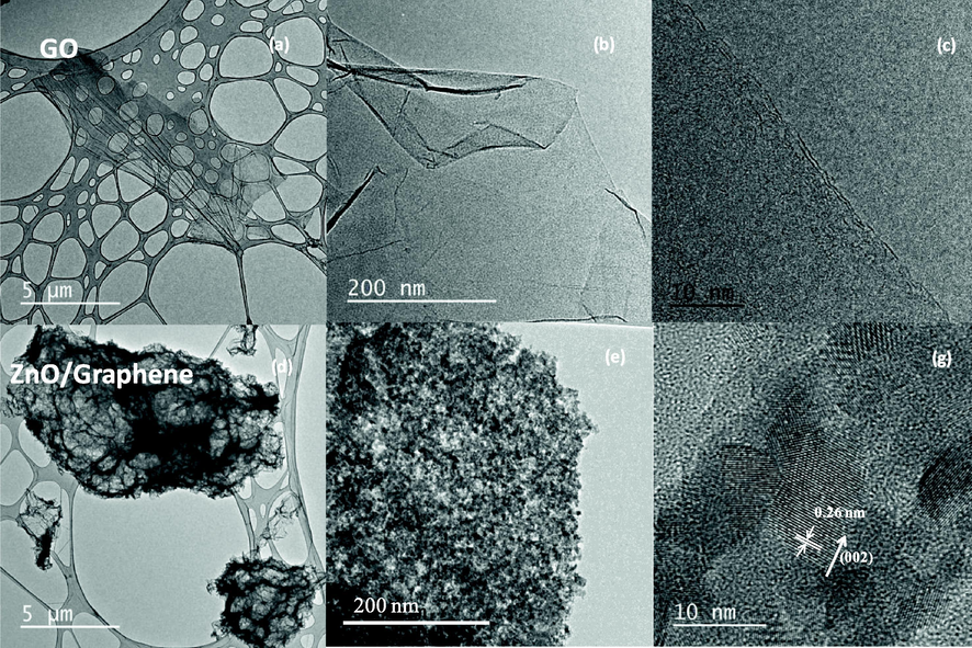
The TEM images of Graphene Oxide flake: (a), (b), (c); and ZnO/Graphene composite: (d), (e), and (g).
From SEM and TEM characterization results, it can be assumed that ZnO nanoparticles were homogenously precipitated on the surface of the RGO during the reduction of GO. In this case, urea acts like a precipitation agent to fabricate ZnO nanoparticle according to work (Tan et al., 2019). Similarly, urea also acts as a reducing agent of GO following to work (Vinh et al., 2019). Therefore, a composite made from ZnO nanoparticles with a particle size around 10 nm and RGO flake can be fabricated by ultrasonic treatment. The result could lead to forming a new methodology for the fabrication of ZnO/Graphene composite.
3.1.3 The X-ray diffraction analysis
Fig. 4 discloses the typical XRD patterns of the GO and ZnO/Graphene composite in a range of 2 θ from 5° to 40°. The XRD spectrum of the as-prepared GO shows (0 0 1) diffraction peak at 2θ = 9.88°, indicating the distance between two Graphene layers is 0.89 nm (Rivera et al., 2019). The result demonstrates that Graphite was completely oxidized into Graphene Oxide (GO) (Stobinski et al., 2014).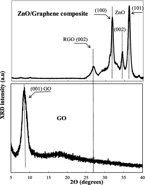
The XRD spectra of GO, and ZnO/Graphene composite.
For ZnO/Graphene composite, the XRD pattern shows that the (0 0 1) diffraction peak at 9.88 of GO shifted to the diffraction peak at 26, which is the typical (0 0 2) diffraction peak of RGO (Vinh et al., 2019). Therefore, the result reveals that GO was reduced to RGO during the ZnO nanoparticle precipitation (Emiru & Ayele, 2017). However, the diffraction peak (0 0 2) of RGO indicates a short-range order of the stacking effect. Furthermore, the diffraction peak of ZnO nanoparticles displays the typical hexagonal wurtzite structure with the characteristic of (0 0 2) plane, and the results are perfectly corresponding to JCPDS file number No. 79–2205 (Chouhan and Yeh, 2015). Moreover, the intensive ratio of (0 0 1) and (0 0 2) diffraction peak of ZnO nanoparticle is around 3 (I1 0 0/I0 0 2 = 3), demonstrating a large proportion of polar surfaces in the ZnO/Graphene composite (Vu & Marbán, 2014).
The crystalline size of the ZnO/Graphene sample was estimated by Scherreŕs equation using the (0 0 2) plane of ZnO nanoparticles, giving a value of 12.4 nm. These XRD results fully agree with the TEM results.
3.1.4 Raman spectroscopy
Raman spectroscopy is used to characterize the lattice vibration of the material. For Graphene characterization, Raman is a vital technique to determine defect formation after the reduction process. Fig. 5 shows the Raman spectra of ZnO nanoparticles, GO, and ZnO/Graphene composite. For ZnO/Graphene composite, the G peak at 1615 cm−1 is related to the sp2- hybridized carbon atoms (Ferrari et al., 2006). And the D peak at 1354 cm−1 is associated with sp3- hybridized carbon atoms in hexagonal lattice structures (Vinh et al., 2019). The D/G intensity ratio of the ZnO/Graphene composite is 1.28; meanwhile, the D/G intensity ratio of GO is 0.89. This result demonstrates the reduction degree of GO during the preparation of the ZnO/Graphene (Ferrari, 2007). The D/G intensity ratio of ZnO/Graphene composite associates to the reduction degree in sp2 domains (King et al., 2016). The Raman results are reasonably agreed with XRD results, demonstrating the reduction of GO to RGO during the ZnO/Graphene composite preparation.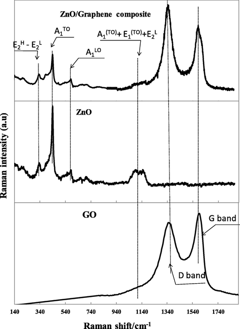
The Raman spectra of GO, ZnO nanoparticles and ZnO/Graphene composite.
3.1.5 N2 adsorption/desorption measurement
The purification efficiency can be evaluated through isotherm characterizations of the adsorbents. Fig. 6 illustrates the N2 adsorption/desorption isotherm of the three samples GO, ZnO nanoparticles, and ZnO/Graphene composite. The isotherms are very unrelated, according to the unique texture structure of the three samples. According to IUPAC classification, the isotherms of GO and ZnO samples can be attributed to hysteresis loop H3 with aggregates of plate-like particles, which gave rise to the slit-shape pore. Meanwhile, the isotherm of ZnO/Graphene composite is assigned to hysteresis loop H4, which can be corresponded to narrow slit pores, as well as pores in the micropore region (Cychosz et al., 2017). This characteristic also approves the predominance of mesopores in the ZnO/Graphene composite, which will be a promising material for several specific purifications (Kalaparthi et al., 2017).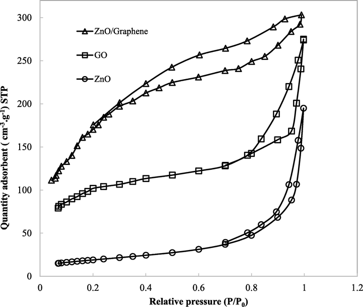
The isotherm results of GO, ZnO nanoparticles and ZnO/Graphene composite.
According to the result, the ZnO/Graphene composite displays the highest specific surface area (320 m2/g), whereas GO, ZnO nanoparticles have lower surface areas, 290 m2/g, and 88 m2/g, respectively. The commercial zeolite exposes a larger specific surface area, 364 m2/g, compared to the ZnO/Graphene composite (Fernández et al., 2014) (Table 1).
Material
SBET (m2/g)
Vp (cm3/g)
L (nm)
ZnO
88
0.27
14.7
GO
290
0.33
15.9
ZnO/Graphene
320
0.29
2.7; 8.1
Zeolite ZSM-5 (Fernández et al., 2014)
364
0.22
1.76
The different shapes of N2 adsorption/desorption isotherm of the three samples can be explained by combining the Graphene layer with ZnO nanoparticles. The presence of ZnO on the RGO surface can prevent the aggregation of RGO layers and keep the separation between them (Wang et al., 2012). In addition, the increase in specific surface area by the presence of ZnO may attribute to the enlargement in micropores due to the development of a pore wall (Park & Kwon, 2020). This phenomenon may explain the different isotherm between the three samples, GO, ZnO nanoparticles, and ZnO/Graphene composite.
Table 1 shows the specific surface area, total volume, and average pore diameter of the ZnO, GO, and ZnO/Graphene composite.
ZnO/Graphene composite has a lower total pore volume of 0.29 cm3/g comparing with that of GO 0.33 cm3/g. But the total pore volume of ZnO/Graphene composite is higher than that of ZnO (0.27 cm3/g) and commercial zeolite (0.22 cm3/g).
According to the literature, we can conclude that the in-situ synthesis of ZnO/Graphene composite (50% wt. ZnO) via sonification in this work gives a higher specific surface area compared with the values of ZnO/Graphene composite synthesized by other methodologies reported in the literature. A comparison of the specific surface area synthesized by different approaches can be found in Table 2.
Methodology
SBET (m2/g)
Reference
Sonification route
320
This work
Freeze-drying and thermal annealing
119.3
Lonkar et al. (2016))
Wet-chemical method
125.2
Wang et al. (2019)
Sol-gel deposition
26.4
Durmus et al. (2019)
Solution precipitation
65.2
Hieu (2018)
Chemical deposition
243
Li et al. (2012)
Wet-chemical method
158
Posa et al. (2016)
Fig. 7 shows the Barret-Joyner-Halenda (BJH) pore size distributions of the three samples: ZnO/Graphene composite, GO and ZnO nanoparticles with the average pore size of 2.7 and 8.1; 15.9; 14.7 nm, respectively (Table 1). According to IUPAC nomenclature and the average pore diameter presented in Table 1, it can be concluded that the ZnO/Graphene composite are mesoporous material (Gupta & Khatri, 2017). The average pore diameter of the ZnO/Graphene composite is 2.7 and 8.1 nm, which may be suitable for the oil purifying (Hsu et al., 2013).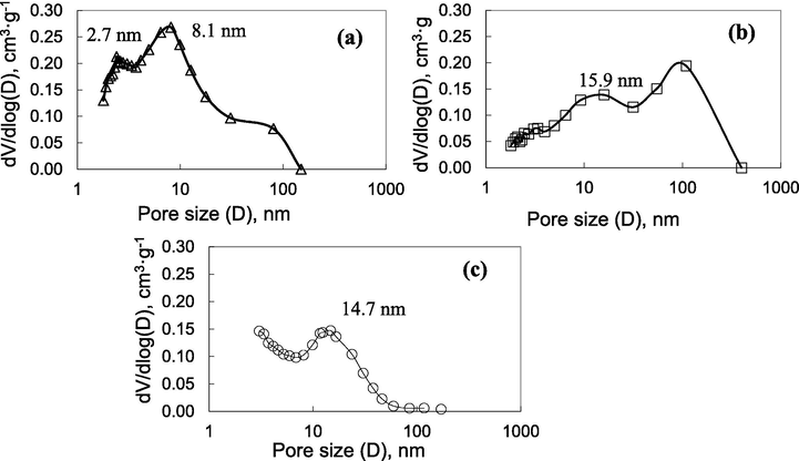
The pore size distribution results of ZnO/Graphene composite (a), GO (b), and ZnO nanoparticles (c).
3.1.6 Elemental analysis
The elemental analysis of the ZnO/Graphene composite, ZnO, GO was carried out by LECO combustion analysis and X-ray Fluorescence analysis (FRX analysis) (Table 3). Carbon, hydrogen, sulfur, and oxygen determination are detected by the combustion and pyrolysis process. And the ash after combustion was characterized by X-ray Fluorescence analysis to determine the Zn content. The elemental analysis was presented in Table 3. The C/O ratio in the sample GO is about 1; after the formation of ZnO/Graphene composite, by deducting the amount of oxygen in ZnO, the C/O ratio of the Graphene sample is 4.
Element, wt %
ZnO
GO
ZnO/Graphene composite
C
0
49.8
40.3
O
19.6
46.6
18.3
S
0
1.2
0.9
H
0
2.4
1.3
Zn
80.4
0
39.4
For the ZnO/Graphene composite, the elemental analysis implied that the 9.6 wt% of the total oxygen content (18.3 wt%) belonged to ZnO material by considering the Zn:O stoichiometry in Table 3. Therefore, 9.2 wt% of the total oxygen content (18.3 wt%) belonged to Graphene material. Thus, the C/O ratio of Graphene in the ZnO/Graphene sample is 4; meanwhile, the C/O ratio in the sample GO is approximately 1. The result showed that GO is completely reduced during the fabrication of ZnO/Graphene composite, and the mass weight ratio between ZnO and Graphene in the composite sample is around 0.95.
3.2 Characterization of the treated oil
3.2.1 Effect of treatment on acidity number of oil
It is already known that oil degradation generates dissolved acids, which harms the power transformer. It is vital to remove the oil acidity number for the proper working of the power transformer. Table 4 shows the acidity of the fresh oil, aged oil, and purified oil using commercial zeolite and ZnO/Graphene composite. The table specifies that acidity is decreased by raising the number of adsorbent materials. The oil sample treated by ZnO/Graphene composite, G-oil-50, provides the closest value compared to the fresh oil. Thus, the dissolved acids were almost entirely removed by using a certain amount of absorbent, ZnO/Graphene composite.
Fresh oil
Aged oil
G-oil-50
G-oil-100
G-oil-150
Z-oil-50
Z-oil-100
Z-oil-150
0.15
0.384
0.18
0.26
0.27
0.30
0.33
0.35
3.2.2 Breakdown voltage
The aged oil has a higher breakdown voltage than the fresh oil due to the moisture, organic acids, formed sludge. In the transformer, if the breakdown voltage parameter of the oil is lower than the limit value, several failures may occur during its function. In this work, the breakdown voltage of oil samples was measured by KEP OLT-80A oil breakdown voltage tester (According to IEC 60156). Tables 5 shows the breakdown voltage value of the fresh, aged, and treated oil samples. The oil samples treated by ZnO/Graphene composite has a higher breakdown voltage value than the oil samples treated by the commercial zeolite. The ZnO/Graphene composite sample's breakdown voltage value is very close to the value of the fresh oil.
Fresh oil
Aged oil
G-oil-50
G-oil-100
G-oil-150
Z-oil-50
Z-oil-100
Z-oil-150
75
33.4
72
68
66
65
50
39
3.2.3 Viscosity
In power transformers, the oil with low viscosity provides a better cooling effect. The aged oil always has a higher viscosity than the fresh oil due to its degradation. Then, it is crucial to decrease the viscosity of the aged oil. Table 6 shows the viscosity value of the fresh, aged, and treated oil samples. The viscosity of the purified oil is lower than the aged oil. Further, the oil-treated by ZnO/Graphene composite has a better viscosity value than the oil-treated by the commercial zeolite. Moreover, the viscosity value of the G-oil-50 sample, treated by ZnO/Graphene composite, is very close to the fresh oil.
Fresh oil
Aged oil
G-oil-50
G-oil-100
G-oil-150
Z-oil-50
Z-oil-100
Z-oil-150
6.5
7.77
6.89
6.92
7.01
7.64
7.69
7.73
3.2.4 Color
The oil color represents the deterioration of the oil in the power transformer. The fresh oil is colorless; thus, the oil deterioration can be determined by the color after its utilization in power transformers. The aged oil usually presents a dark color because of its impurities. In this work, the color of the aged oil was determined by Spectrophotometric Colorimeters OKATON C-105, according to ASTM D1500 (Petroleum products-determination of color- ASTM scale). The variation of the color after purifying is presented in Table 7. The results demonstrate a fundamental enhancement in the color of the treated oil using ZnO/Graphene composite.
Fresh oil
Aged oil
G-oil-50
G-oil-100
G-oil-150
Z-oil-50
Z-oil-100
Z-oil-150
0.5
3.0
0.8
1.2
1.5
1.3
1.7
2.2
Fig. 8 shows the comparison of the three oils' color: oil samples treated by ZnO/Graphene composite, the aged oil, and the oil-treated by the commercial zeolite. It is noticeable that the oil sample treated by ZnO/Graphene composite has the colorless compared with the oil sample treated by zeolite and aged oil.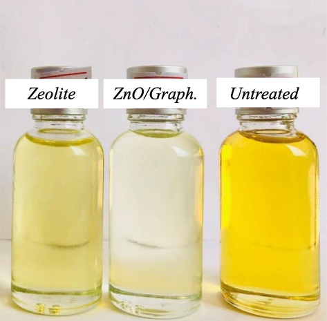
The visual aspect of the oil-treated by ZnO/Graphene composite, aged oil and the oil treated by the commercial zeolite.
The results above conclude that the ZnO/Graphene composite shows higher efficiency treatment than the commercial zeolite. All the treated oil parameters by ZnO/Graphene composite are very close to the fresh oil compared with the oil sample treated by zeolite. The results can be explained by the ZnO/Graphene composite's textural structure, which has a higher specific surface area compared with the commercial zeolite (Guliyev et al., 2018). Furthermore, a suitable average pore diameter of the ZnO/Graphene composite considers an agreement between high purification capacity (large pore size) and short black-run (small pore size) (Bockisch, 1998). Moreover, the 3D structure of the ZnO/Graphene composite with high mechanical resistance (Blanco, 2020), suitable pore size, low tendency to become stuck (Dou et al., 2020). may improve the purification capacity of the ZnO/Graphene composite.
4 Conclusion
For the first time, the ZnO/Graphene composite was fabricated through the reduction of GO in the presence of urea via sonochemical routes. The urea acts as a reducing agent to reduce GO and acts as a precipitation agent to obtain ZnO nanoparticles. The SEM and TEM characterizations show that the ZnO nanoparticles are homogeneously distributed on the layer of RGO. XRD analysis reveals that ZnO nanoparticles have high polar surfaces, and the GO was highly reduced to RGO. The ZnO/Graphene composite synthesized in this work shows a higher specific surface area than many others synthesized by other approaches. Besides, its average pore size discloses that this material is a mesoporous material with the size suitable for the aged oil purification.
As far as we know, this is the first work that has used ZnO/Graphene composite as an adsorbent for the transformer oil purification. The result shows that the aged oil sample treated by the ZnO/Graphene composite has a larger enhancement property comparing with the aged oil sample treated by the commercial zeolite. This result may due to the mesoporous structure of the composite ZnO/Graphene, its 3D structure, and the unreduced oxygen functional groups and the vacancy defects on the surface of the RGO flake, which could provide a high purification capacity for aged transformer oil.
Acknowledgments
This research is funded by Vietnam National Foundation for Science and Technology Development (NAFOSTED) under grant number 104.03-2018.350.
Declaration of Competing Interest
The authors declare that they have no known competing financial interests or personal relationships that could have appeared to influence the work reported in this paper.
References
- Reduced graphene oxide as a highly efficient adsorbent for 1-naphthol and the mechanism thereof. RSC Adv.. 2014;4(93):51624-51631.
- [CrossRef] [Google Scholar]
- Facile synthesis of zinc oxide nanoparticles decorated graphene oxide composite via simple solvothermal route and their photocatalytic activity on methylene blue degradation. J. Photochem. Photobiol., B. 2016;162:500-510.
- [CrossRef] [Google Scholar]
- The use of composite materials in 3D printing. J. Compos. Sci.. 2020;4(2):42.
- [CrossRef] [Google Scholar]
- Bockisch, M. (Ed.), 1998. Chapter 7—Oil Purification. In: En Fats and Oils Handbook. AOCS Press, pp. 613–718. https://doi.org/10.1016/B978-0-9818936-0-0.50012-3.
- Regeneration of insulating mineral oil by carbonated amorphous calcium phosphate–chitosan adsorbent. Process Saf. Environ. Prot.. 2007;85:327-331.
- [CrossRef] [Google Scholar]
- Chouhan, N., L. Yeh, C., F. Hu, S., H. Huang, J., W. Tsai, C., Liu, R.-S., S. Chang, W., & H. Chen, K., 2015. JES-Neelu-Array of CdSe QD-Sensitized ZnO Nanorods Serves-1103-2010.
- Adsorption behaviour of reduced graphene oxide towards cationic and anionic dyes: co-action of electrostatic and π – π interactions. Mater. Chem. Phys.. 2017;194:243-252.
- [CrossRef] [Google Scholar]
- Recent advances in the textural characterization of hierarchically structured nanoporous materials. Chem. Soc. Rev.. 2017;46(2):389-414.
- [CrossRef] [Google Scholar]
- Hydrothermal synthesis of zinc oxide-reduced graphene oxide nanocomposites for an electrochemical hydrazine sensor. RSC Adv.. 2015;5(29):22935-22942.
- [CrossRef] [Google Scholar]
- Self-driven membrane filtration by core–shell polymer composites. J. Mater. Chem. A. 2020;8(31):15942-15950.
- [CrossRef] [Google Scholar]
- Synthesis and characterization of graphene oxide/zinc oxide (GO/ZnO) nanocomposite and its utilization for photocatalytic degradation of basic fuchsin dye. ChemistrySelect. 2019;4(1):271-278.
- [CrossRef] [Google Scholar]
- Controlled synthesis, characterization and reduction of graphene oxide: a convenient method for large scale production. Egypt. J. Basic Appl. Sci.. 2017;4(1):74-79.
- [CrossRef] [Google Scholar]
- Electrooxidation of 2-chlorophenol and 2,4,6-chlorophenol on glassy carbon electrodes modified with graphite–zeolite mixtures. J. Appl. Electrochem.. 2014;44(12):1295-1306.
- [CrossRef] [Google Scholar]
- Raman spectrum of graphene and graphene layers. Phys. Rev. Lett.. 2006;97(18):187401.
- [CrossRef] [Google Scholar]
- Raman spectroscopy of graphene and graphite: disorder, electron–phonon coupling, doping and nonadiabatic effects. Solid State Commun.. 2007;11
- [Google Scholar]
- Drying of transformer insulation using zeolite. Electr. Insulat. IEEE. 2004;20:20-30.
- [CrossRef] [Google Scholar]
- Investigation of activated carbon obtained from the liquid products of pyrolysis in sunflower oil bleaching process. Int. J. Ind. Chem.. 2018;9(3):277-284.
- [CrossRef] [Google Scholar]
- One-pot synthesis of graphene/zinc oxide by microwave irradiation with enhanced supercapacitor performance. RSC Adv.. 2016;6(23):19394-19403.
- [CrossRef] [Google Scholar]
- Reduced graphene oxide as an effective adsorbent for removal of malachite green dye: Plausible adsorption pathways. J. Colloid Interface Sci.. 2017;501:11-21.
- [CrossRef] [Google Scholar]
- Electrochemistry of ZnO@reduced graphene oxides. Carbon. 2018;130:480-486.
- [CrossRef] [Google Scholar]
- Synthesis of zinc oxide/graphene oxide nanocomposites as antibacterial materials against staphylococcus aureus and escherichia coli. Vietnam J. Sci. Technol.. 2018;55(1B):266.
- [Google Scholar]
- Mesoporous carbon aerogel membrane for phospholipid removal from Jatropha curcas oil. Sep. Purif. Technol.. 2013;109:129-134.
- [CrossRef] [Google Scholar]
- Reclamation of old transformer oil using kaolin clay. Int. J. Adv. Sci. Techn. Res.. 2015;5:752.
- [Google Scholar]
- Self-assembly of multi-hierarchically structured spongy mesoporous silica particles and mechanism of their formation. J. Colloid Interface Sci.. 2017;491:133-140.
- [CrossRef] [Google Scholar]
- A new raman metric for the characterisation of graphene oxide and its derivatives. Sci. Rep.. 2016;6(1):19491.
- [CrossRef] [Google Scholar]
- Facile synthesis of ZnO–reduced graphene oxide nanocomposites for NO2 gas sensing applications. Eur. J. Inorg. Chem.. 2015;2015(11):1912-1923.
- [CrossRef] [Google Scholar]
- ZnO/graphene-oxide nanocomposite with remarkably enhanced visible-light-driven photocatalytic performance. J. Colloid Interface Sci.. 2012;377(1):114-121.
- [CrossRef] [Google Scholar]
- Graphene/ZnO nanocomposite with seamless interface renders photoluminescence quenching and photocatalytic activity enhancement. J. Mater. Sci.. 2018;53(19):13924-13935.
- [CrossRef] [Google Scholar]
- Effect of oil regeneration on improving paper conditions in a distribution transformer. Energies. 2019;12:1665.
- [CrossRef] [Google Scholar]
- In situ formed graphene/ZnO nanostructured composites for low temperature hydrogen sulfide removal from natural gas. RSC Adv.. 2016;6(84):81142-81150.
- [CrossRef] [Google Scholar]
- One-pot sonochemical synthesis of ZnO nanoparticles for photocatalytic applications, modelling and optimization. Materials (Basel, Switzerland). 2019;13(1)
- [CrossRef] [Google Scholar]
- Transformer oil regeneration by combining several strategies enhanced by the use of four adsorbents. IET Gener. Transm. Distrib.. 2017;11
- [CrossRef] [Google Scholar]
- Preparation of novel mesoporous silica using a self-assembled graphene oxide template. Sci. Rep.. 2020;10(1):6173.
- [CrossRef] [Google Scholar]
- Graphene-ZnO nanocomposite for highly efficient photocatalytic degradation of methyl orange dye under solar light irradiation. Korean J. Chem. Eng.. 2016;33(2):456-464.
- [CrossRef] [Google Scholar]
- A review on properties, opportunities, and challenges of transformer oil-based nanofluids. J. Nanomater.. 2016;2016:1-23.
- [CrossRef] [Google Scholar]
- Graphene and graphene oxide as effective adsorbents toward anionic and cationic dyes. J. Colloid Interface Sci.. 2011;361(1):270-277.
- [CrossRef] [Google Scholar]
- Rivera, L.M., Betancur, A.F., Zarate, D.G., Torres, D.T., Hoyos, L.M., Garcia, A.G., 2019. Reduction and simultaneous doping of graphene oxide to repel LDL in treatment of atherosclerosis disease. arXiv:1902.01850 [cond-mat, physics:physics]. http://arxiv.org/abs/1902.01850.
- Regeneration of transformer insulating fluids using membrane separation technology. Energies. 2019;12:368.
- [CrossRef] [Google Scholar]
- Study Transf. Oil Purificat.. 2017;4(3):4.
- Sonochemical synthesis of iron-graphene oxide/honeycomb-like ZnO ternary nanohybrids for sensitive electrochemical detection of antipsychotic drug chlorpromazine. Ultrason. Sonochem.. 2019;59:104696.
- [CrossRef] [Google Scholar]
- Reactive adsorption of hydrogen sulfide on graphite oxide/Zr(OH)4 composites. Chem. Eng. J.. 2011;166(3):1032-1038.
- [CrossRef] [Google Scholar]
- Visible-light-enhanced interactions of hydrogen sulfide with composites of zinc (oxy)hydroxide with graphite oxide and graphene. Langmuir. 2012;28(2):1337-1346.
- [CrossRef] [Google Scholar]
- Zinc (hydr)oxide/graphite based-phase composites: effect of the carbonaceous phase on surface properties and enhancement in electrical conductivity. J. Mater. Chem.. 2012;22(16):7970-7978.
- [CrossRef] [Google Scholar]
- Graphene oxide and reduced graphene oxide studied by the XRD, TEM and electron spectroscopy methods. J. Electron Spectrosc. Relat. Phenom.. 2014;195:145-154.
- [CrossRef] [Google Scholar]
- Sulaiman, A.-Z., Noura, H., Fardoun, A.A., 2011. Using Activated Carbon from waste date-pits as an adsorbent for transformer oil regeneration. In: 2011 World Congress on Sustainable Technologies, WCST 2011.
- Facile template in-situ fabrication of ZnCo2O4 nanoparticles with highly photocatalytic activities under visible-light irradiation. Bullet. Chem. React. Eng. Catal.. 2019;14(2):404-417.
- [CrossRef] [Google Scholar]
- Adsorption capacities of reduced graphene oxide: effect of reductants. Mater. Res. Express. 2019;6(7):075615.
- [CrossRef] [Google Scholar]
- Sacrificial template synthesis of high surface area metal oxides. Example: an excellent structured Fenton-like catalyst. Appl. Catal. B, s. 2014;152–153:51-58.
- [CrossRef] [Google Scholar]
- Graphene-like porous ZnO/graphene oxide nanosheets for high-performance acetone vapor detection. Molecules. 2019;24(3)
- [CrossRef] [Google Scholar]
- Reduced graphene oxide/ZnO composite: reusable adsorbent for pollutant management. ACS Appl. Mater. Interfaces. 2012;4(6):3084-3090.
- [CrossRef] [Google Scholar]
- Preparation of composite graphene hydrogels adsorbent with special-shaped ZnO and TiO2. Colloids Surf., A. 2019;581:123783.
- [CrossRef] [Google Scholar]
- Environmentally friendly reduced graphene oxide as a broad-spectrum adsorbent for anionic and cationic dyes via π–π interactions. J. Mater. Chem. A. 2016;4(31):12126-12135.
- [CrossRef] [Google Scholar]
- Fiber-shaped ZnO/graphene schottky photodetector with strain effect. Adv. Mater. Interf.. 2018;5(11):1800136.
- [CrossRef] [Google Scholar]


