

Translate this page into:
Influence of change in obstacle blocking rate gradient on LPG explosion behavior
⁎Corresponding author at: College of Safety Science and Engineering, Liaoning Technical University, Huludao, Liaoning 125105, China. qiaozhenglong0927@163.com (Zhenglong Qiao)
-
Received: ,
Accepted: ,
This article was originally published by Elsevier and was migrated to Scientific Scholar after the change of Publisher.
Peer review under responsibility of King Saud University.
Abstract
The aim of this study was to examine the propagation characteristics of liquified petroleum gas (LPG)/air explosion. As such, the flame propagation process and pressure parameters of LPG explosion with an equivalent ratio of 1 were obtained using horizontal, long straight pipes and a high-speed camera. The large eddy simulation and power-law flame model were used to reproduce the simulation results, and the morphological evolution of the flame front during the explosion process was analyzed. The results showed that as the blockage ratio gradient increased, the time required for the flame to propagate from the electrode to the end of the pipe increased. Meanwhile, a flocculent flame formed at the end of the pipeline with a blockage ratio of 91%. Additionally, the maximum flame propagation speed changed in the same way as the blockage ratio. The gradient change of the barrier blockage ratio considerably influenced the pressure kinetics characteristics of LPG explosion: the maximum explosion pressure increased first and then decreased, the time to reach the maximum explosion pressure increased, and the deflagration index increased first and then decreased. The chemical kinetics analysis of premixed gas showed that when propane, n-butane, and isobutane were present in the premixed system, some of the elemental reactions that promote n-butane consumption inhibited propane and isobutane consumption. Meanwhile, the formation and consumption rate of H*, O*, and OH* from LPG during the explosion process was less than that of single-component combustible gas except propane.
Keywords
Liquefied petroleum gas (LPG)
Explosion
Large eddy simulation (LES)
Blockage ratio
Gradient

1 Introduction
Liquefied petroleum gas (LPG) is a clean, efficient energy source and has been widely used in the chemical industry and for civil applications (Zhang et al., 2017). LPG mainly comprises propane and butane, and then ethane, propylene, propyne, and ammonia (Huo and Chow, 2017). A systematic explosion resulting from LPG can cause considerable damage to life and property (Qian et al., 2021). When LPG leaks or escapes from a pressure vessel because of its low boiling point, it creates vapor that explodes upon encountering an external ignition source. Therefore, the study of the combustion and explosion characteristics of LPG is focuses on improving its fuel utilization rate.
The discussion on deflagrant flame propagation characteristics in pipelines can be traced back to the work of Mallard et al. (Mallard et al., 1883). Ellis et al. (Ellis and OCde, 1928) first discovered the “tulip” flame form produced by premixed gas explosion in a confined space. The formation of a “tulip” flame mainly consists of four stages: hemispherical flame, fingertip flame, flat flame, and “tulip” flame, and Clanet et al. (Clanet and Searby, 1996) developed mathematical models for each stage. Subsequently, many scholars have explored the possibility of influencing flame propagation and diffusion, notably Rayley–Taylor (RT) (Starke and Roth, 1986) instability, Kelvin–Helmholtz(KH) (Wang et al., 2021) instability, and Darius–Landau(DL) (Dold and Joulin, 1995; Matalon and McGreevy, 1994; Larrouturou et al., 1993; Gonzalez et al., 1992; Luo et al., 2021) instability.
Several other studies have investigated the combustion and explosion of LPG. Huo et al. and Liao et al. (Huo and Chow, 2017; Liao et al., 2005) studied the propagation characteristics of laminar and turbulent flame during LPG/air deflagration. They noted that the flame propagation rate is related to the turbulent combustion rate and diffusion rate per time, whereas the laminar flame speed is related to the LPG/air equivalent ratio and dilution rate. Razus et al. and Huzayyin et al. (Razus et al., 2009; Huzayyin et al., 2008) investigated the effects of different equivalent ratios, initial pressure, and initial temperature on the explosive characteristics of LPG. They found that these factors considerably influenced the explosion pressure parameters. Lee et al. and Zhang et al. (Lee et al., 2012; Zhang et al., 2017) conducted tests and numerical simulations on the explosion performance of LPG, and they analyzed the explosion characteristics by considering the explosion overpressure, explosion pressure rise rate, and explosion flame propagation speed. The authors found that the flame velocity and overpressure increased with increasing equivalent ratio and mixing ratio of DME to DME-LPG. For enclosures with an exhaust port, the dynamic pressure generated by the indoor LPG explosion exceeded the exhaust port, regardless of whether obstacles were in the enclosure.
On the effect of obstacles on explosion flames, the literature has mainly discussed the structure, number, and blocking ratio of obstacles (Chen et al., 2016; Moen et al., 1982; Park et al., 2008; Wan et al., 2019; Wang et al., 2021). For example, obstacles with mutated edges (e. g., squares and triangles) greatly accelerate flame propagation more than circular obstacles (e.g., a smooth surface) do (Nguyen et al., 2021; Wang et al., 2017; Yu et al., 2016). The distance between obstacles and pores also influences the degrees of turbulence (Chen et al., 2017). Additionally, an increase in the number of obstacles increases the deformation and pressure of the flame front; however, when the number of obstacles reaches the limit, a change in overpressure no longer applies (Hall et al., 2009; Lv et al., 2016; Na’inna et al., 2013). The blocking rate of obstacles also affects the speed of flame propagation in the pipeline. In general, an increase in the obstacle blocking rate increases the peak velocity of the flame front, intensifying the coupling effect between the flame and vortex (Li et al., 2017). Li et al. (Li et al., 2017; Wang et al., 2020) discussed the influence of different obstacle parameters on the combustion of methane (hydrogen)/air mixture, laying a theoretical basis for further investigating the flame diffusion mechanism in the pipeline.
Previous studies have shown that obstacles have either inhibition or enhancement effects on the explosion characteristics of premixed gas (Bartknecht, 2012; Wang et al., 2020). Generally, obstacles considerably affect the detonation performance of premixed gas, increasing the degree of explosion risk of premixed gas (Qiao et al., 2022). However, the flame diffusion and pressure characteristics of LPG/air deflagration under the influence of obstacles are not well understood. Therefore, experimental and numerical simulations were conducted in this study to investigate the deflagration behavior of premixed LPG/air mixtures by examining the gradient change of the barrier blockage ratio. The effects of blockage ratio on flame propagation characteristics, combustion time, explosion pressure, and deflagration index were determined and analyzed. Despite extensive studies on the explosion mechanisms by which blockage ratio affects combustible gases, details of the explosive behavior of the gradient variation in the obstacle blockage ratio in the LPG/air mixture remain unclear. Hence, we conducted a series of experimental and numerical simulations of an LPG/air mixture explosion with a barrier blockage ratio gradient change in the pipeline; the LPG/air equivalent ratio was 1. The results showed that as the blockage ratio gradient increased, the flame morphology, flame propagation speed, and overpressure dynamic characteristics varied. The results of this study are of crucial significance to the transportation and storage of LPG. Meanwhile, the results also lay a foundation for studying the explosive behavior of other combustible gases in obstacles scenarios.
2 Materials and methods
2.1 Experimental materials
The experimental gas was provided by Ping An Gas Co., ltd. of China, and the gas was used to determine the composition and explosion limit of LPG. The results are presented in Table 1. The compressed air composition was 21 % oxygen and 79 % nitrogen. Fig. 1 illustrates the obstacle used in the experiment; the thickness was 1 mm (the influence of obstacle thickness on the experimental results was not considered), and the distance between the center of the circular hole was 12 mm. Table 2 presents the environmental conditions of the experiment.
Gas components
Volume fraction (%)
Explosive limit (%)
UFL
LFL
Ethane (C2H6)
0.03
12.95
2.65
Propylene (C3H6)
1.13
2.03
11.12
Propane (C3H8)
28.59
2.13
9.54
Butene (C4H8)
1.56
1.62
10.09
n-Butane (n-C4H10)
22.77
1.96
8.58
i-Butane (i-C4H10)
44.67
2.43
10.47
Ammonia(NH3)
1.25
15.71
27.45
Experiment conditions.
Parameter
Value
Temperature
24 °C
Atmospheric pressure
101.3 Pa
Air humidity
80 %
Oxygen concentration
20.8 %
2.2 Experimental device and methods
The experimental setup is illustrated in Fig. 2 and consists of six parts: explosion pipeline, pressure data acquisition system, high-speed camera, gas distribution system, remote ignition system, and synchronous control system. The premixed gas was ignited by a spark discharge. The diameter of the electric spark was 2 mm, the energy was 800 mJ, and the duration was 1 s. The inner diameter of the pipe was 100 mm while the outer diameter was 110 mm. Qiao et al. detailed this equipment in their work (Qiao et al., 2022).
Schematic of the experimental system.
Before the experiment, compressed air was fed into the explosion pipe, displacing the air in the pipe. The valve was closed, the pipe was sealed with polyethylene film, and the experimental gas was prepared according to Dalton’s partial pressure law. Subsequently, the circulation system was opened for 180 s to ensure that the gas spread uniformly to all parts of the pipeline. After the gas cycle, the gas was allowed to stabilize in the pipeline for 10 min (Alharbi et al., 2014; Razus et al., 2019). Before ignition, a gas concentration meter was used to measure the concentration of LPG in the pipeline. As LPG mainly comprises propane, n-butane, and i-butane, the volume fraction of propane and butane in the pipeline was measured by a gas concentration meter before the experiment. When the volume fraction of propane and butane was 3.1 % (±0.1 %) and 0.97 % (±0.1 %), respectively, the next step was performed; where the value was not reached, the above process was repeated. The process was performed three times for each working condition, and the error bar was used to express the standard deviation of the test results.
2.3 Flame image processing method
The Canny algorithm was used for the binary processing of the flame images at different time points. The flame propagation speed was calculated using the location coordinates of the white pixels representing the flame front.
Maximum displacement distance of flame front
First, the flame image is gray-scale and binarized by a cyclic function. The boundary of the flame region is determined by obtaining the flame edge, and a trigonometric function is used to measure the distance between all white pixels of the flame front and the electrode. The maximum value of the result corresponds to the position of the flame tip, as shown in Fig. 3.
Calculation of maximum flame propagation speed
- Position of flame front at different times.
The position of the flame tip at the current and previous moments is used to calculate the maximum propagation speed of the flame at the current moment. The formula is as follows:
where vf is the propagation speed of the explosion flame, ms−1; xn+1 is the horizontal position of the flame tip in the pipe at the current moment, m; xn is the horizontal position of the flame tip in the pipe at the last moment, m; and Δt is the difference between the corresponding time of xn+1 and xn, s.
Blockage ratio calculation
The ratio of the obstacle area to the cross-sectional area of the pipeline is typically used to represent the barrier blockage ratio φ:
where SBR is the obstacle area, m2; and SA is the cross-sectional area of the explosion tube, m2.
3 Numerical model
3.1 Physical model and meshing
Four kinds of straight cylindrical tubes were used in the numerical calculation (Fig. 4): one semi-closed pipe without obstacles and three semi-closed pipes with obstacles. The pipes were sealed at one end and completely open to the atmosphere at the other. For the obstacle pipelines, porous jump boundary Conditions were used to simplify the porous region on the obstacle. Owing to the finite thickness of the obstacle, the pressure variation was defined as a combination of Darcy’s law and the additional inertia loss term:
Physical model and multi-space region simplification.
where μ is the laminar fluid viscosity, α is the medium permeability, C2 is the pressure step coefficient, v is the velocity perpendicular to the porous surface, ρ is the fluid density, and Δm is the medium thickness.
Meanwhile, the pressure change can also be expressed as:
where
where k is the loss factor, f is the opening rate, D is the diameter of the circular hole, c1 is the center distance of the transverse circular hole, and c2 is the center distance of the longitudinal circular hole.
According to Eqs. (3), (4), (5), and (6), the value of the pressure jump coefficient C2 of the obstacle in the experiment is 3241.47.
In the large eddy simulation, the physical diffusion at the subnetwork scale decreases as the mesh size decreases. Therefore, no strict “grid independence” exists in large eddy calculations. In the calculation, the grid scale should be reduced as much as the accuracy and time cost permit. However, in practice, limited computing resources make it necessary to test the grid independence. The grid generation in this study was also based on independence testing. All four physical models used hexahedral grids. The grid size was 1.5 mm, and the total number of grids was 1.553 million, 1.582 million, 1.591 million, and 1.591 million, respectively, for Conditions 1 to 4.
3.2 Sublattice combustion model
The governing equation for the large eddy model was developed using the Favre filter for the mass, momentum, energy, and component conservation equations. The control equation of the large eddy model was obtained similarly and coupled with the constitutive equation and the equation of state. The component migration equation was reconstructed in the form of the migration equation for the reaction progress variable c, which is defined as the normalized sum of the mass fractions of the product components. For example c = 0, where the mixture is not burned, and c = 1, where the mixture is completely burned.
where u represents the unburned reactant, Yk represents the mass fraction of the kth substance, and the superscript eq represents the chemical balance; αk is the reactant constant.
The sublattice combustion model used in this study was the power-law flame wrinkle model proposed by Charlette et al (Charlette et al., 2002). The sublattice reaction rate was modeled by the following formula:
where ρu is the density of unburned gas, Sl is the laminar flame speed, and ΞΔ is the sublattice fold coefficient. To consider the coupling between flame development and unresolved scale turbulence, the sublattice fold coefficient was modeled by the following formula:
where β is a constant; Δ is the filter size, set to Δ = V1/3, V is the cell volume; Ck is Kolmogorov constant; δf is the laminar flame thickness, δf = 4ν/Sl, and ν is kinematic viscosity; ReΔ is the sub-grid turbulent Reynolds number; Γ is an effective equation to describe the stretching effect of all turbulence scales smaller than the filter size Δ.
3.3 Boundary conditions
In the numerical simulation, the outlet boundary was the pressure outlet, and the rest was the wall boundary. The near wall function uses the Werner–Wengle function. The combustible gas was filled in according to Table 1 before ignition. The simulated initial temperature and pressure were 297.15 K and 101,325 Pa, respectively. The spark mode was used for ignition, with an ignition radius of 2 mm and ignition energy of 800 MJ.
4 Results and discussion
4.1 Flame structure and shape evolution
Fig. 5 (a) illustrates the change in flame front under different working conditions. Under all conditions, the flame was similar before crossing the barrier; that is, it changed from spherical flame to “fingertip” flame (Yao et al., 2021). When LPG/air was ignited, the initial flame expanded around the electrode to form a spherical flame. Then, when the flame reached near the pipe wall, the combusted gas at the flame skirt pushed the flame and unburned gas forward because of thermal expansion. Meanwhile, the flame could not move in the vertical direction because of the restriction of the pipe wall. Therefore, before the flame reached the obstacle, the flame front maintained the “fingertip” shape.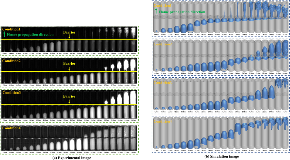
Explosion flame propagation process at different conditions.
Under Condition 4, when the pipe was empty, the flame behavior was similar to the initial behavior. When the flame entered Pipe 2, the flame spread in a “fingertip” shape. Owing to the membrane breaking effect, the pressure generated by the explosion was released, accelerating the gas reaction rate. Until 34.5 ms, the front end of the flame gradually tended to assume a flat shape, and the flame brightness decreased considerably. At 35.5 ms, the flame on both sides of the pipe axis moved toward the axis. The flame shape became similar to “tulip” at 36.0 ms. The formation of this flame pattern is related to RT instability. When the polyethylene film at the end of the pipe was torn by the pressure inside the pipe, the gas density inside the flame and the gas density in front of the flame front changed in different ways under the effect of thermal expansion and the split flow at the end of the pipe. Thus, a strong turbulence effect was created, making the flame center sink inward and forming a “tulip like” flame.
However, as obstacles reduced the cross section of the pipe, the flame gradually elongated after passing through the obstacles, and then spread to the pipe wall at a certain position of the pipe. This is because the shape of the flame near the obstacle is determined by the thermal expansion of the burned gas driving the flow of the unburned gas (Zheng et al., 2022). When the blockage rate of the obstacle increased, the ability of the thermal expansion to drive the unburned gas increased, and the movement distance of the unburned gas along the pipeline axis increased. Therefore, the flame lengthening distance increased.
Under Condition 1, when the flame spread toward the pipe wall in Pipe 2, the flame was flocculent, and the flame had a reverse propagation in the Pipe 2. The flocculent appearance resulted from the interaction between the edge of the obstacle and the vortex separated from the flame (Wang et al., 2022). Reverse flame propagation is the result of the reverse movement of unburned gas in the tube driven by the thermal expansion of the diffusion flame.
Under Condition 2, when the flame diffused to the pipe wall through the obstacle, a “torch” flame shape appeared. This observation is different from the triple flame formed in a confined space (Wu et al., 2022). When air flows through an obstacle, a turbulent shear layer forms on the surface of the obstacle. A shear layer prevents the internal unburned gas from burning. Meanwhile, a circulation area is formed on the shear surface. The film breaking effect stops the flame from moving along the shear surface to the obstacle to form a triple flame, but it continues to spread to the end of the pipe.
Under Condition 3, the blocking rate of obstacles decreased, increasing airflow through obstacles. Therefore, the flame did not stretch after passing through the obstacles. As the flame approached the obstacles in the form of a “finger,” the flame at the axis first passed through the obstacles. Therefore, under this working condition, the shape of the flame passing through the obstacle was conical.
To observe the three-dimensional structure of the explosion flame front, the equivalent surface of process variable c = 0.1 was selected to approximate the premixed flame front (Li et al., 2022) (Fig. 5 (b)). A comparison of the experimental photos shows that the large eddy current simulation results were consistent with the experimental results. In addition, the power-law model successfully reproduced the phenomenon of the “tulip like” flame front in the obstacle-free condition and the fold of the flame after passing through the obstacle in the obstacle-free condition.
Under Conditions 3 and 4, a comparison of the experimental and simulation results shows that the fold degree of the flame under the experimental conditions was greater than that of the simulation results. Additionally, the time required for the flame to reach the outlet from the electrode was lesser in the experiment. The main cause of errors in the large eddy simulation was the amplification effect of the WALE subgrid filtering; no errors were observed in the gas component detection.
4.2 Flame propagation speed
The change rule of the flame front position illustrated in Fig. 6 can be calculated using equation (1). The colored annotation in the figure indicates the location of the obstacle. This study focused on determining how the change in gradient of the blockage rate of obstacles in the pipeline affects the explosion of LPG/air; thus, Fig. 6 only illustrates the propagation of the flame before it reaches the end of the pipeline.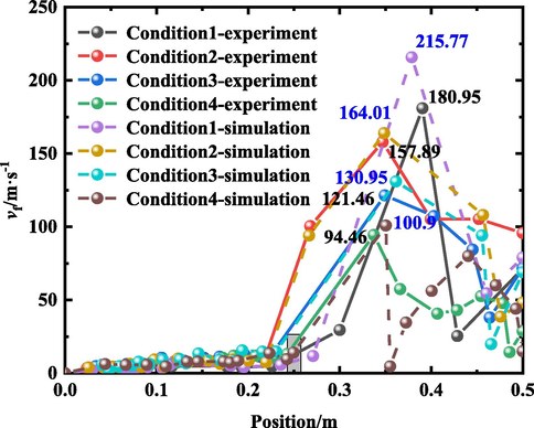
Flame tip front propagation speed at different position.
Fig. 6 shows that the flame speed changed in the same way upon reaching the position of the obstacle, regardless of whether an obstacle was in the pipe. The flame propagation speed fluctuated from 0 to 0.25 m into the pipe, and the variation range was small. Except under Condition 4 (without an obstacle), the blockage rate of obstacles in the pipe affected the maximum flame propagation speed in the pipe. Under the experimental conditions, the maximum flame propagation speed under working Conditions 1 and 2 was 4.96 m/s and 9.57 m/s, respectively, in the pipe. Compared with Condition 4, the value decreased by 62.4 % and 27.5 %, respectively. Under the simulated conditions, the maximum flame propagation speed in the pipe was 9.10 m/s and 10.06 m/s. Compared with Condition 4, the value decreased by 33.4 % and 26.4 %, respectively. Thus, when the blockage ratio of the obstacle was 0.91 and 0.75, respectively, in this experiment, the obstacle reduced the burning rate of the mixed gas between the electrode and the obstacle. On the contrary, under Condition 3, the maximum flame propagation velocity of the 0–0.25 m range of the pipe was 14.77 m/s and 15.56 m/s, respectively, which was 11.9 % and 13.7 % higher than that of Condition 4. Thus, when the blockage ratio of the obstacle was 0.55, the obstacle increased the maximum flame propagation speed in the pipe section.
Under the same blocking conditions, the difference between the maximum flame propagation speed of the experiment and the simulation was 34.82 m/s, 6.12 m/s, 9.49 m/s, and 6.44 m/s, respectively, and the relative errors were 6.13 %, 3.73 %, 7.25 %, and 6.38 %, respectively. The average relative error between the experiment and simulation was 8.37 %. Regarding the time to reach the maximum flame propagation speed, the difference between the experimental results and simulation results was mainly caused by the neglect of wall heat transfer in the numerical simulation. Hence, the reaction speed of the gas in the simulation process was higher than that in the experiment, increasing the flame propagation speed. However, when the flame passed through the obstacle, the change in the flame propagation speed was more obvious. The maximum propagation velocity of the flame in the 0.25–0.5 m range of the pipe increased with increasing blockage ratio gradient of obstacles. The maximum flame propagation speed increased by 91.6 %, 67.2 %, and 28.6 %, respectively, comparing the values under Conditions 1 to 3 with that under Condition 4 in the experiments. Similarly, the simulation results increased by 113.8 %, 62.5 %, and 29.8 % respectively. Fig. 7 shows that the change trend of the maximum flame propagation speed growth rate is the same as that of the blockage rate of obstacles. It can be observed from the figure that when the flame passed through the obstacle, the gradient of the blockage ratio of the obstacle increased, and the growth rate of the maximum propagation speed of the flame also increased.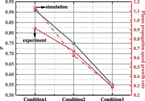
Variation of maximum flame propagation speed growth rate with blockage ratio.
4.3 Comparative analysis of explosion pressure
Fig. 8(a) shows the explosion pressure curve of LPG/air mixture under different experimental conditions. It can be observed that the change trend of the pressure time curve was the same in each group of experiments. Additionally, the placement of obstacles in the pipe increased the maximum explosion pressure monitored by the pressure sensor at the end of the pipe.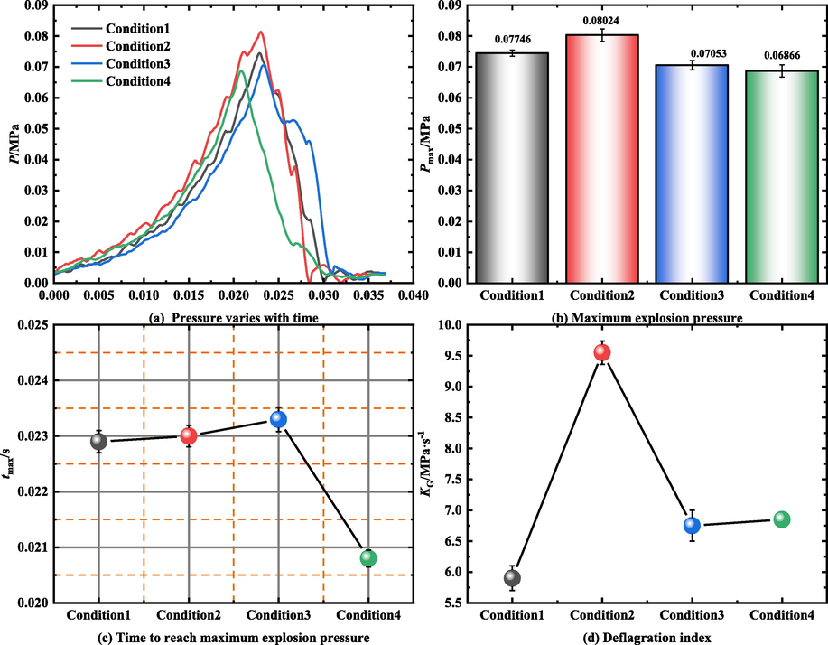
Pressure dynamic parameters.
The maximum explosion pressure Pmax and deflagration index KG are important indicators of the explosive intensity of premixed gas (Li et al., 2012; Nie et al., 2014). Fig. 8(b) illustrates the Pmax value at the end of the pipe during the explosion of LPG/air under different working conditions. The figure shows that the Pmax value of the obstacle-placement experiment was greater than that of the barrier-free experiment. Hence, the obstacles accumulated the pressure generated by the explosion. This is because, during pressure accumulation, the pressure wave exhibits diffraction, refraction, reflection, offsetting, superposition, and other behaviors. These behaviors have slight influence on the combustion rate of premixed gas when the blockage rate of obstacles is small (operating Conditions 2 and 3); therefore, the value of Pmax increased. When the blockage rate of the obstacles was large (Condition 1), the pressure wave behavior mentioned above decreased the combustion rate of premixed gas. The premixed gas in the tube was not fully burned when the seal gas film broke. Therefore, the Pmax value under Condition 1 was lower than that under Conditions 2 and 3. According to the change in the blockage ratio and the similarity of the position relation of the electrode, obstacle, and sensor, the experimental results in Reference (Luo et al., 2021) were compared with the experimental results in this study. An observation of the variation trend of Pmax shows that the variation of Pmax is related to the blocking probability. When the blockage rate of the obstacle increased gradually, the value of Pmax increased first and then decreased during the explosion of premixed gas. This variation trend is similar to that reported in Reference (Luo et al., 2021). In this study, Pmax reached the maximum at a blocking rate of 0.75; in the Reference (Luo et al., 2021), Pmax reached the maximum at a blocking rate of 0.6. This result shows that the effect of porous obstacles on explosion pressure is smaller than that of flat obstacles.
Fig. 8(c) illustrates the time required for the explosion pressure to reach the maximum explosion pressure under different experimental conditions. Fig. 5 shows that when obstacles were added to the pipeline, the value of tmax increased with increasing blocking rate of obstacles. Compared with the barrier-free experiment, the tmax values of the obstacle placement experiment increased by 10.1 %, 10.6 %, and 12.0 %, respectively. This was mainly because obstacles accumulate explosion pressure, reducing the reaction rate of key reaction steps with high pressure sensitivity in a chain reaction.
Fig. 8(d) illustrates the deflagration index of premixed gas during explosion under different experimental conditions. The deflagration index KG is crucial to the development of industrial protective equipment and the application of anti-explosion technology (Wang et al., 2020). The formula is as follows:
where KG is the deflagration index; (dP/dt)max is the maximum value of pressure change rate; and V is the volume of the explosive pipe.
In the literature (Chen et al., 2016, 2017; Clanet and Searby, 1996; Dold and Joulin, 1995; Ellis and OCde, 1928; Gonzalez et al., 1992; Hall et al., 2009; Huo and Chow, 2017; Huzayyin et al., 2008; Larrouturou et al., 1993; Lee et al., 2012; Li et al., 2017; Liao et al., 2005; Luo et al., 2021; Lv et al., 2016; Mallard et al., 1883; Matalon and McGreevy, 1994; Moen et al., 1982; Na’inna et al., 2013; Nguyen et al., 2021; Park et al., 2008; Qian et al., 2021; Razus et al., 2009; Starke and Roth, 1986; Wan et al., 2019; C. Wang et al., 2021; Wang et al., 2017; Z. Wang et al., 2021; Yu et al., 2016; Zhang et al., 2017), different explosion containers were used for experimentation, so V1/3 cannot represent the characteristic length of all containers. For long straight pipes, V1/3 is replaced with the ratio of pipe length L to pipe diameter D. Therefore, equation (16) was modified in this study:
In the experiment, the pressure sensor is placed at the end of the pipe; hence, we studied the explosion hazard of the pressure sensor location. It can be seen from Fig. 8(d) that the change in the deflagration index was related to the blockage rate of obstacles. When the blockage rate of the obstacles was 91 %, the deflagration index decreased because of a reduction in the LPG/air reaction rate. When the blockage rate of the obstacles was 55 %, the deflagration index was close to that of the barrier-free experiment. Under this condition, the presence of obstacles did not affect the deflagration index at the end of the pipe. When the blockage rate of the obstacle was 75 %, the deflagration index at the end of the pipe was significantly increased under this working condition. It can be seen from Fig. 8(b) that the risk of explosion of premixed gas in the pipeline was the greatest.
If the uncertainty of the experiment is considered, the variation trend of Pmax, tmax, and KG would not change within the error range. Additionally, the difference of each parameter is less than 5 % in the three experiments under the same conditions.
5 Chemical kinetic analysis
The micro mechanism can be better revealed through the study of the chemical kinetics of the mixture. Because LPG plays an important role in the energy system, many chemical reaction mechanisms have been proposed, such as GRI Mech3.0, USC Mech2.0, Mehl mechanism, n-C4H8 Kin mechanism, and Marinov mechanism (Fischer and Jiang, 2016). Some scholars have verified the reliability of n-C4H8 Kin mechanism on the chemical kinetics mechanism of ethane, propane, and butane (Bagheri et al., 2020; Ranzi et al., 2014, 2015). The combustible gases used in this study were ethane, propylene, propane, butene, n-butane, isobutane, and ammonia; thus, the n-C4H8 Kin mechanism was used for the chemical kinetics analysis. The mechanism includes 159 reactants and 2,459 elementary reactions.
5.1 Sensitivity analysis
The results of the sensitivity analysis of propane, n-butane, i-butane, and temperature during the explosion of LPG/air mixture are illustrated in Fig. 9. It can be seen from Fig. 9 that the main reactions promoting the consumption of propane, n-butane, and isobutane during LPG/air explosion were R5, R68, R75, R114, R177, R208, R226, R415, R449, R581, R582, R593, and R1141. The reactions that promoted the formation of propane, n-butane, and isobutane were R20, R37, R141, R154, R381, R384, R411, R586, R597, and R618. Here, R5, R37, R75, and R593 had the highest sensitivity coefficients. A comparison of the elementary reactions of the three substances in the figure shows that the elementary reactions promoting the change in propane and isobutane were consistent, whereas the elementary reactions promoting the change in n-butane were different from those of propane and i-butane. Meanwhile, the same elementary reaction had opposite sensitivity coefficients. This is because when propane and isobutane were consumed in the system, elementary reactions R326, R327, R330, R331, R332, R333, R343, R344, R583, R585, R587, and R911 converted propane and isobutane to n-butane (Fig. 10). In addition, when n-butane was consumed, elementary reactions R20, R141, R154, R381, and R384 inhibited the consumption of propane and i-butane.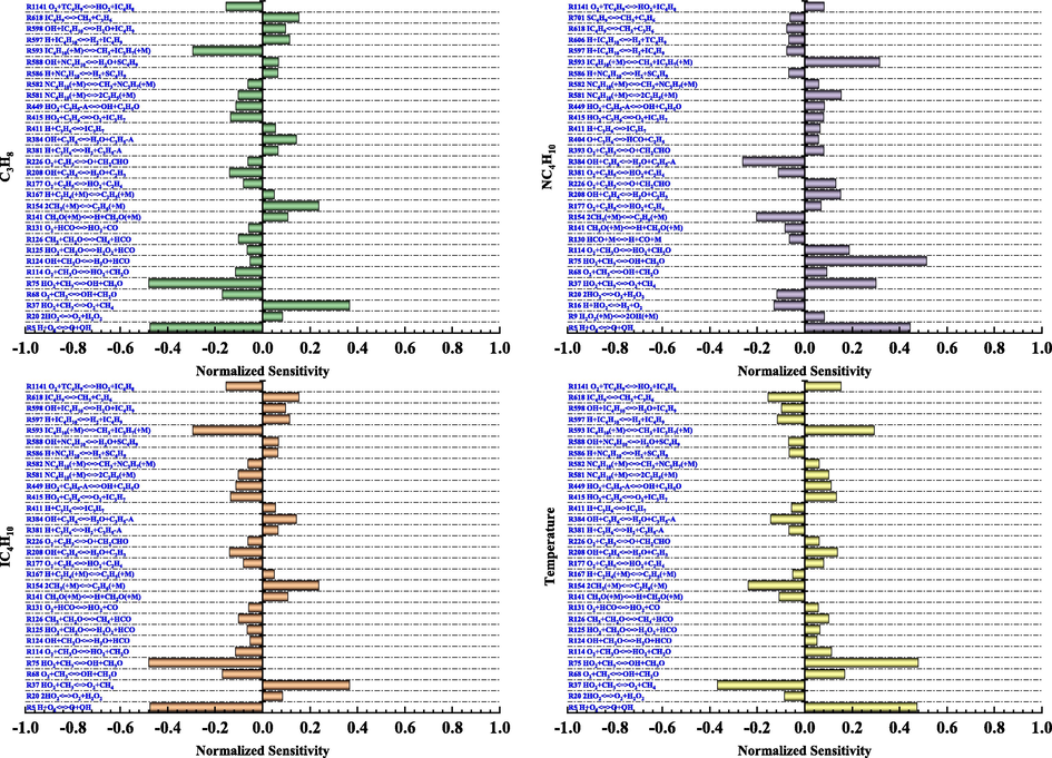
Propane, n-butane, isobutane, and temperature sensitivity.
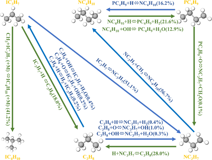
Propane and i-butane to n-butane reaction path.
By comparing the temperature sensitive and substance sensitive elementary reactions in Fig. 9, we find that the temperature sensitive elementary reactions were the same as the propane and isobutane sensitive elementary reactions, and the signs of the sensitivity coefficients of the same elementary reactions were opposite. For example, as shown in Fig. 9(a) and 9(b), R124, R125, and R126 promoted the consumption of propane and isobutane. As shown in Fig. 9(d), the sensitivity coefficients of these three elementary reactions were positive, promoting temperature rise. Hence, the consumption of propane and isobutane in LPG increases the temperature of the system. However, a comparison of the same elemental reactions in Fig. 9(b) and Fig. 9(d) shows that the signs of the sensitivity coefficients of these elemental reactions were consistent. Thus, the formation and consumption of n-butane were synchronized with the increase and decrease in the system temperature.
5.2 O*, H*, and OH* productivity analysis
In LPG explosion, the existence of free radicals sustains the chain reaction, and O*, H*, and OH* are the main factors affecting the change in chain reaction (Nie et al., 2017; Razus et al., 2009, 2010). Fig. 9 shows that the main elementary reactions controlling the change in sensitivity coefficients of different substances are the same. Fig. 11 illustrates the yields of H*, O*, and OH* of the main elementary reactions after an explosion under the condition of equivalence ratio of 1 for combustible gas. See Table 3 for detailed elementary reaction equations.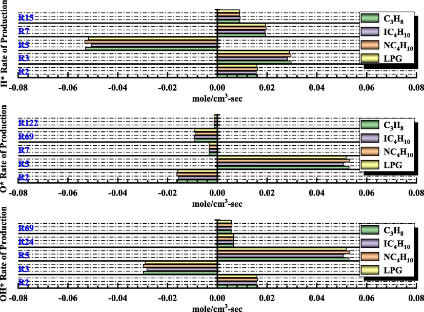
H*, O*, and OH* rate of production.
Reactions
Equation
R2
H2 + O<=>H + OH
R3
H2 + OH<=>H + H2O
R5
H + O2<=>O + OH
R7
O + H2O<=>2OH
R15
H + HO2<=>2OH
R24
OH + CO<=>H + CO2
R69
O + CH3<=>H + CH2O
R122
O + CH2O<=>OH + HCO
Fig. 11 shows that during the explosion of the LPG/air mixture, the basic reactions that affected the generation and consumption rate of free radicals were R2, R3, R5, R7, R15, R24, R69, and R122. R2 and R7 increased the generation rate of H*, and R5 increased the consumption rate of H*. R5 was the main elementary reaction to increase the rate of O* formation. R2, R7, R69, and R122 increased the consumption rate of O*. R2, R5, R24, and R69 increased the production rate of OH*, whereas R3 increased the consumption rate of OH*. Compared with propane and n-butane, the formation and consumption rates of H*, O*, and OH* in the same elementary reaction were slightly reduced. Compared with isobutane, the rate of formation and consumption of three free radicals increased slightly.
6 Conclusion
The flame propagation process, pressure characteristics, and chemical kinetics characteristics of premixed LPG/air in long and straight pipes were investigated using high-speed cameras and pressure sensors. Meanwhile, numerical and chemical kinetic models of the pipe were established, and the relationship between the flame front and eddy current in the pipe were obtained. The main findings of the study are summarized as follows:
Before the flame passes through an obstacle, the shape of the flame front and the change in the flame propagation speed are similar. After passing through the obstacle, the flame is stretched by thermal expansion and turbulence effects. As the gradient of the obstacle blockage rate increases, the flame stretching distance decreases. In addition, when the blockage rate of obstacles is low, the flame forms a flocculent flame at the end of the pipe.
The maximum propagation speed of the flame increases as the gradient of the blockage ratio increases. The change in flame propagation velocity represents the influence of turbulence in the pipe on the flame front. As the blockage rate increases, the propagation velocity change of the flame after passing through the obstacle becomes more intense, and the turbulence intensity in the pipe becomes greater. The trend of flame acceleration and deceleration differs under different obstacle conditions. RT instability is the main cause of turbulence in pipelines with an obstacle, and turbulence increases the local combustion rate of premixed gas by increasing the flame front area and energy transfer. A higher combustion rate accelerates the flame propagation and increases the flow velocity of unburned gas.
When obstacles are added to the pipe, tmax and Pmax at the end of the pipe increase, and the change in KG depends on the blocking ratio of the obstacles. This phenomenon is due to the following factors. First, obstacles with a high blocking rate accumulate pressure, reduce the combustion rate of premixed gas, increase the pressure propagation time, and reduce the value of (dP/dt)max. Then, the film breaking effect reduces the pressure in the pipeline as well as the diffraction, refraction, reflection, offset, and superposition of pressure waves.
The existence of n-butane in LPG affects the consumption of propane and i-butane in the system. Some elementary reactions that promote the decomposition of n-butane inhibit the consumption of propane and i-butane. Additionally, compared with single-component combustible gas, the rate of generation and consumption of H*, O*, and OH* of LPG during explosion is generally lower than that of single-component combustible gas. In the early stage of explosion, the reaction rate of free radicals is reduced by adding some reactants to the combustible gas to achieve the effect of explosion suppression.
Acknowledgements
This work was financially supported by the National Natural Science Foundation of China(no. 52074148).
The authors would like to thank all the reviewers who participated in the review, as well as MJEditor (www.mjeditor.com) for providing English editing services during the preparation of this manuscript.
Declaration of Competing Interest
The authors declare that they have no known competing financial interests or personal relationships that could have appeared to influence the work reported in this paper.
References
- Turbulent premixed flames of CNG, LPG, and H2 propagating past repeated obstacles. Exp. Therm. Fluid Sci.. 2014;56:2-8.
- [Google Scholar]
- Comprehensive kinetic study of combustion technologies for low environmental impact: MILD and OXY-fuel combustion of methane. Combust. Flame.. 2020;212:142-155.
- [Google Scholar]
- Explosions: course, prevention, protection. Springer Science&Business Media; 2012.
- A power-law flame wrinkling model for LES of premixed turbulent combustion Part II: dynamic formulation. Combust. Flame.. 2002;131(1–2):181-197.
- [Google Scholar]
- Experimental and LES investigation of premixed methane/air flame propagating in a chamber for three obstacle BR configurations. J. Loss Prev. Process Ind.. 2016;41:48-54.
- [Google Scholar]
- Experimental and LES investigation of premixed methane/air flame propagating in a tube with a thin obstacle. Combust. Theory Modell.. 2017;21(02):274-292.
- [Google Scholar]
- An evolution equation modeling inversion of tulip flames. Combust. Flame.. 1995;100(3):450-456.
- [Google Scholar]
- A chemical kinetic modelling study of the combustion of CH4–CO–H2–CO2 fuel mixtures. Combust. Flame.. 2016;167:274-279.
- [Google Scholar]
- Interaction of a flame front with its self-generated flow in an enclosure: The “tulip flame” phenomenon. Combust. Flame.. 1992;88(02):201-220.
- [Google Scholar]
- Effects of position and frequency of obstacles on turbulent premixed propagating flames. Combust. Flame.. 2009;156(02):439-446.
- [Google Scholar]
- Flame propagation of premixed liquefied petroleum gas explosion in a tube. Appl. Therm. Eng.. 2017;113:891-901.
- [Google Scholar]
- Laminar burning velocity and explosion index of LPG-air and propane-air mixtures. Fuel.. 2008;87(01):39-57.
- [Google Scholar]
- Numerical investigations of the tulip flameinstability—comparisons with experimental results. Combust. Sci. Technol.. 1993;87(1–6):69-89.
- [Google Scholar]
- Experimental investigations on the deflagration explosion characteristics of different DME-LPG mixtures. Fire Saf. J.. 2012;49:62-66.
- [Google Scholar]
- Premixed methane/air flame propagating in an obstructed chamber with different BRs and spatial configurations. J. Loss Prev. Process Ind.. 2017;47:66-71.
- [Google Scholar]
- Explosion characteristics of H2/CH4/air and CH4/coal dust/air mixtures. Powder Technol.. 2012;229:222-228.
- [Google Scholar]
- Comparative study on explosion characteristics of hydrogen and gasoline vapor in a semi-confined pipe based on Large Eddy Simulation. Fuel.. 2022;328:125334
- [Google Scholar]
- Correlations for laminar burning velocities of liquefied petroleum gas–air mixtures. Energy Convers. Manage.. 2005;46(20):3175-3184.
- [Google Scholar]
- Effects of an obstacle on the deflagration behavior of premixed liquefied petroleum gas-air mixtures in a closed duct. Energy.. 2021;234:121291
- [Google Scholar]
- Combined effects of obstacle position and equivalence ratio on overpressure of premixed hydrogen-air explosion. Int. J. Hydrogen Energy.. 2016;41(39):17740-17749.
- [Google Scholar]
- Recherches experimentales ettheoriques sur la combustion des melanges ga-zeux explosives n.d. H. Dunod et E. Pinat. 1883
- [Google Scholar]
- An evolution equation modeling inversion of tulip flames. Combust. Flame.. 1994;25(01):1407-1413.
- [Google Scholar]
- Pressure development due to turbulent flame propagation in large-scale methaneair explosions. Combust. Flame.. 1982;47(1):31-52.
- [Google Scholar]
- The acceleration of flames in tube explosions with two obstacles as a function of the obstacle separation distance: the influence of mixture reactivity. J. Loss Prev. Process Ind.. 2013;26(6):1597-1603.
- [Google Scholar]
- A 2D CFD model investigation of the impact of obstacles and turbulence model on methane flame propagation. Process Saf. Environ. Prot.. 2021;146:95-107.
- [Google Scholar]
- Laboratory investigation into fractal characteristics of methane explosion flame. Process Saf. Prog.. 2014;34(03):244-249.
- [Google Scholar]
- Chemical kinetic characteristics of methane/air mixture explosion and its affecting factors. J. Loss Prev. Process Ind.. 2017;49:675-682.
- [Google Scholar]
- Experiments on the effects of multiple obstacles in vented explosion chambers. J. Hazard. Mater.. 2008;153(1–2):340-350.
- [Google Scholar]
- Cause Analysis of the Large-Scale LPG Explosion Accident Based on Key Investigation Technology: A Case Study. ACS Omega.. 2021;6(31):20644-20656.
- [Google Scholar]
- Effect of a Perforated Polyethylene Material on Propane−Air Explosion in a Confined Space. ACS Omega. 2022;7:24746-24756.
- [Google Scholar]
- Reduced Kinetic Schemes of Complex Reaction Systems: Fossil and Biomass-Derived Transportation Fuels. Int. J. Chem. Kinet.. 2014;46(09):512-542.
- [Google Scholar]
- New reaction classes in the kinetic modeling of low temperature oxidation of n-alkanes. Combust. Flame.. 2015;162(05):1679-1691.
- [Google Scholar]
- Initial pressure and mixture composition influence on LPG-air confined explosions. Rev. Chim.. 2009;60:750-754.
- [Google Scholar]
- Explosion characteristics of LPG–air mixtures in closed vessels. J. Hazard. Mater.. 2009;165(1–3):1248-1252.
- [Google Scholar]
- Burning Velocity of Liquefied Petroleum Gas (LPG)-Air Mixtures in the Presence of Exhaust Gas. Energy Fuels.. 2010;23:1487-1494.
- [Google Scholar]
- Additive influence on maximum experimental safe gap of ethylene-air mixtures. Fuel.. 2019;237:888-894.
- [Google Scholar]
- An experimental investigation of flame behavior during cylindrical vessel explosions. Combust. Flame.. 1986;66(03):249-259.
- [Google Scholar]
- Effect of side vent size on a methane/air explosion in an end-vented duct containing an obstacle. Exp. Therm. Fluid Sci.. 2019;101:141-150.
- [Google Scholar]
- Effect of a tilted obstacle on the flame propagation of gas explosion in case of low initial pressure. Combust. Sci. Technol.. 2021;193(14):2405-2422.
- [Google Scholar]
- Influence of different types of obstacles on the propagation of premixed methane-air flames in a half-open tube. Energies.. 2017;10(11):10111908.
- [Google Scholar]
- An experimental investigation on explosion behaviors of syngas-air mixtures in a vessel with a large blockage ratio perforated plate. Fuel. 2020;264:116842
- [Google Scholar]
- Study on the inhibition of Al-Mg alloy dust explosion by modified Mg(OH)2. Powder Technol.. 2021;384:284-296.
- [Google Scholar]
- Flame propagation and spectrum characteristics of CH4-air gas mixtures in a vertical pressure relief pipeline. Fuel.. 2022;317:123413
- [Google Scholar]
- Experimental investigation on the effect of obstacle position on the explosion behaviors of the non-uniform methane/air mixture. Fuel.. 2022;320:123989
- [Google Scholar]
- On explosion characteristics of premixed syngas/air mixtures with different hydrogen volume fractions and ignition positions. Fuel.. 2021;288:119619
- [Google Scholar]
- Gas explosion flame propagation over various hollow-square obstacles. J. Nat. Gas Sci. Eng.. 2016;30:221-227.
- [Google Scholar]
- Explosion hazards of LPG-air mixtures in vented enclosure with obstacles. J. Hazard. Mater.. 2017;334:59-67.
- [Google Scholar]
- Effect of obstacle location on explosion dynamics of premixed H2/CO/Air mixtures in a closed duct. Fuel.. 2022;324:124703
- [Google Scholar]


