

Translate this page into:
Nanotubes as polymer composite reinforcing additive materials – A comparative study
⁎Corresponding author. fiser@uni-miskolc.hu (Béla Fiser)
-
Received: ,
Accepted: ,
This article was originally published by Elsevier and was migrated to Scientific Scholar after the change of Publisher.
Peer review under responsibility of King Saud University.
Abstract
Abstract
Nitrogen-doped bamboo-shaped carbon nanotubes (N-BCNTs) and their non-doped conventional counterparts, multiwalled carbon nanotubes (MWCNTs) were compared as polymer reinforcing additives in polyvinyl chloride (PVC) matrix. The nanotubes were synthetized by catalytic chemical vapor deposition (CCVD) method. The purity of both nanotubes was measured by thermogravimetric analysis (TGA) and found to be >91%. Further analysis on the morphology and size of the carbon nanotubes (CNTs) were performed by transmission electron microscopy (TEM). The PVC powder was impregnated with CNTs in ethanol by using tip ultrasonicator. The dispersion media was evaporated, and the CNT/PVC powder was used to produce polymer fibers. The orientation of carbon nanotubes in the PVC matrix was characterized by scanning electron microscopy (SEM), and the presence of nanotubes were confirmed in case of all PVC samples. It can be observed on the SEM images that the nanotubes are fully covered with PVC. The tensile strength of the nanotube containing samples was tested and the N-BCNT/PVC composite was found to be better in this sense, thanks to the extraordinary structure of the nanotube. In case of the N-BCNT/PVC composite the measured young modulus was 39.7% higher, while the elongation at brake decreased by 33.6% compare to the MWCNT/PVC composite. These significant differences in the mechanical properties of the composites can be explained with the stronger interaction between N-BCNTs and PVC.
Keywords
N-BCNT
MWCNT
Polyvinyl chloride
Polymer composite

1 Introduction
Polyvinyl chloride (PVC) is the third-most widespread polymer, and it is inevitable for our modern daily life (bottles, packaging, plastic cards, electrical cable insulation, etc.). The mechanical and thermal properties of PVC can be tuned for different applications by using fillers, such as glass (Liang, 2002), clay (Peprnicek et al., 2006), wood fibers (Matuana et al., 1998), calcium carbonate (Sun et al., 2006) bamboo, and pine flour (Ge et al., 2004). It is known that suspension type PVC resin has a hierarchical supramolecular structure and the grains are highly porous (Hattori et al., 1972). This type of resin can absorb high quantity solution additives which makes possible the so called dry-blend technology and solid materials can also be added into the grains.
Carbon Black (CB) was studied as PVC filler (Islam et al., 2018). The tensile strength of CB-PVC composites increased with the amount of CB until 15 wt%, then decreased, but elongation at break decreased with increasing CB-content (Islam et al., 2018). Nanostructured materials are frequently used as composite reinforcing additives (Wang et al., 2015; Vadukumpully et al., 2011; Broza et al., 2007). Han Wang et al. made multilayer graphene (MLG)-PVC composites (Wang et al., 2015). This composite has higher tensile modulus and glass transition temperature, but lower tensile strength and thermal stability (Wang et al., 2015).
Sajini et al. reported that graphene-filled PVC nanocomposites have flexible conductivity, high mechanical strength and thermal stability (Vadukumpully et al., 2011). Carbon nanotubes (CNTs) have also been used as filler to improve the electrical and thermal conductivity of PVCs (Broza et al., 2007). Carbon nanotube containing cation exchange PVC membranes were developed by using solution casting (Hosseini et al., 2013). Bikiaris examined multiwalled carbon nanotube (MWCNT)-polypropylene (PP) nanocomposites and found that the MWCNT act as reinforcing agent (tensile strength increased) when it is used in a small amount (2–2.5 wt%) (Bikiaris Dimitrios, 2010). However, increased MWCNT content undermined the mechanical properties of the composite (Bikiaris Dimitrios, 2010).
Mudassir and Moonyong prepared PVC/MWCNT and PVC/graphene nanocomposites (Hasan and Lee, 2014). PVC/graphene films had a smoother surface morphology, compare to PVC/MWCNT films (Hasan and Lee, 2014). MWCNTs tend to aggregate in the polymer matrix (van der Waal interactions), which prevents their widespread usage as PVC fillers.
Deep and his co-workers functionalized the nanofiller to increase the dispersion in the matrix (Deep and Mishra, 2018). It was observed that the tensile strength is strongly dependent on the functionalized MWCNT content (Deep and Mishra, 2018). The tensile strength of MWCNT/PMMA (polymethyl methacrylate) composite increased up to 0.5 wt% MWCNT, and then it decreases (Deep and Mishra, 2018). The MWCNT addition showed 16% increase in tensile strength (Deep and Mishra, 2018). This fluctuation may be caused by the high viscosity of the polymer in melt-state, which makes it difficult to disperse the functionalized MWCNT in the medium.
Mashhadzadeh et al. examined the effect of functionalizing carbon nanotubes (OH functionalization and silanization) on the mechanical behavior of CNT/Polymer nanocomposites (Hamed Mashhadzadeh et al., 2017). The results showed that the functionalization increased the adsorption energy as well as the mechanical properties (Hamed Mashhadzadeh et al., 2017). The OH-functionalization and silanization increased the tensile strength by 9% and 16%, respectively (Hamed Mashhadzadeh et al., 2017). The functionalization had a beneficial effect on the flexural strength as well (OH-functionalization 7%, silanization about 36% increment) (Hamed Mashhadzadeh et al., 2017).
Promising counterparts of the multiwall carbon nanotubes are the nitrogen or boron doped carbon nanotubes (N- or B-doped CNT) which have a bamboo like structure (Panchakarla et al., 2010). If nitrogen is incorporated into the CNT structure three main types of nitrogen can be differentiated: pyridinic, pyrrolic and graphitic (Inagaki et al., 2018). The pyridinic and the pyrrolic type nitrogens are bonded to two carbon atoms as a member of a six or five-membered ring, respectively. These can occur at the edge of the carbon layer, but also possible to appear far from the edges if vacancies are associated with the incorporation sites. These vacancies and edges could serve as adsorption sites which is responsible for the extraordinary structure of the N-doped CNTs. The N-doped nanotubes can also be synthetized by chemical vapor deposition (CVD) such as their non-doped counterparts (Arjmand et al., 2016).
Nanotubes are proved to be effective polymer reinforcing materials, but there are still difficulties in their usage. To test and compare their applicability, nitrogen-doped bamboo-shaped carbon nanotubes (N-BCNTs) and multiwalled carbon nanotubes (MWCNTs) as polymer composite reinforcing compounds were studied in polyvinyl chloride (PVC) matrix.
2 Experimental
2.1 Materials
N-butylamine (Sigma Aldrich) and acethylene gas (Messer) were used as carbon sources during the CCVD synthesis of the nanotubes. Nickel(II)-nitrate hexahydrate (Merck), iron(III)-nitrate nonahydrate (VWR), cobalt(II)-nitrate hexahydrate (Sigma Aldrich), and magnesium oxide (Sigma Aldrich) were used as catalysts, while Patosolv, mixture of aliphatic alcohols (VWR) were applied as solvent. Concentrated (36 wt%) hydrochloride acid was used for eliminating the remained catalysts from the synthesized carbon nanotubes. Commercial products were used to prepare the reference PVC composite: suspension type PVC resin with K value 70 (ONGROVIL S-5070), di-(2-ethyl-hexyl) terephthalate plasticizer (Plastsoft DOTP), Ca-Zn heat stabilizer (Reagens CL357) and fatty acid ester type internal lubricant (Loxiol G71).
2.2 Methods
2.2.1 Synthesis of nitrogen-doped bamboo-shaped carbon nanotubes (N-BCNT)
CCVD method was used to synthesize N-BCNTs in a quartz reactor (OD 60 mm) by using a tube furnace. Carbon source, N-butylamine was injected to the quartz reactor by a syringe pump. The synthesis was carried out over 20 min at 700 °C using 2.5 g of Ni/MgO catalyst. The catalyst was made from nickel-nitrate hexahydrate salt. Magnesium oxide was impregnated with aqueous solution of the nickel salt and the nickel content was kept at 5 wt%. In the nickel-nitrate solution the magnesium-oxide was suspended by ultrasonic homogenizer. The water was evaporated by vacuum rotary evaporator, after the Ni/MgO catalyst was dried at 120 °C overnight. The flow rate of the carrier gas (nitrogen, purity 99.995%) during the CCVD process was 150 scc, while the flow rate of the carbon source was 6 ml/h. To remove the catalyst from the final N-BCNT product 36 wt% hydrochloride acid was used.
2.2.2 Synthesis of multiwalled carbon nanotubes (MWCNT)
Multiwalled carbon nanotubes were synthesized using the CCVD procedure in a quartz tube reactor. The carbon source was acetylene gas (99.95%), the flow rate was 20 scc, which was regulated by a flowmeter. The carrier gas was nitrogen with a flow rate of 150 scc. The reaction was carried out over 30 min at 750 °C using 2.5 g catalyst. The catalyst was prepared by using iron(III)-nitrate-nonahydrate, cobalt(II)-nitrate hexahydrate, and magnesium-oxide as catalyst support. The purification of MWCNTs was carried out by hydrochloride acid.
2.2.3 Ultrasonic dispersion of carbon nanotubes in PVC
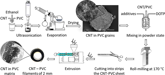
During the conventional extrusion method, when CNTs were mixed directly into the PVC powder, dispersing nanotubes in PVC mixture is proved to be very difficult and results extrudates of rough surface. Therefore, ultrasonic treatment in a non-swelling solvent was applied to improve homogeneity and ingest the nanotubes into the highly porous PVC grains (Fig. 1).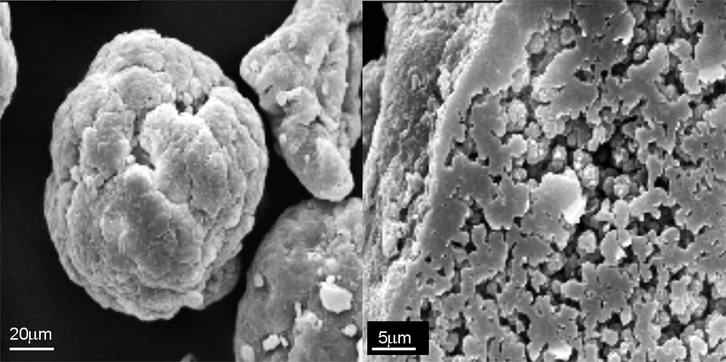
Photomicrograph of a PVC grain and its slice.
50 g of PVC resin, 400 ml ethanol and the corresponding amount of carbon nanotube (1–5 w/w%) were mixed in a beaker. The N-BCNT and PVC was dispersed in ethanol by Hielscher UIP1000hdt ultrasonic homogenizer (340 W/19.42 kHz). The ethanol was evaporated by rotary vacuum evaporator and the resin was dried to constant weight.
2.2.4 Preparation of plasticized PVC/carbon nanotube composites (CNT)
The following basic formulation to prepare PVC composite was used in the production of CNT/PVC composites (Table 1).
Type of additive
Trade name
Qty. (phr)
PVC
S-PVC K70 Ongrovil S-5070
100/102.1/105.3
Plasticizer
Plastoft DOTP
30
Stabilizer
Reagens CL357
1.2
Internal lubricant
Loxiol G71
0.7
In case of carbon nanotube containing PVC resins, the real PVC content was weighted, and the exact carbon nanotube content calculated accordingly. By this way the PVC/plasticizer ratio is kept constant. The components were mixed by hand in a bowl and roll milled on a twin roll-mill for 5 min at 170 °C. The roll milled plates of about 0.4 mm thickness were cut to strips suitable for feeding the extruder. The extrusion was carried out on a Göttfert Extrusiometer 20 single screw laboratory extruder with a screw of 1:4 compression ratio and a cylindrical die of 2 mm diameter and 30 mm length. The temperature was set to 150/160/170 °C. The extruded filaments were tested by tensile and microscopy.
2.2.5 Characterization of carbon nanotubes and the nanotube-PVC polymer composites
The characterization of the structure and morphology of the two different nanotubes was carried out by high resolution transmission electron microscopy (HRTEM, FEI Technai G2). The carbon content (purity) of the nanotubes was determined by thermogravimetric analysis (TG, NETCHS). The distribution of the nanotubes in the PVC matrix was studied by scanning electron microscopy (SEM, AMRAY 18301). SEM micrographs of PVC grains were taken with a JEOL JSM IT-100 electron microscope in secondary electron mode. Samples were gold plated by sputter coater. Relatively thick, 10 nm gold layer was deposited because the PVC has a high inclination to electrostatic charging. The tensile tests of extruded PVC/carbon nanotube composite filaments were carried out by an Instron 5566 universal testing machine at room temperature (23 ± 1 °C) and tensile speed was 20 mm/min, while pneumatic grips were used. The incorporated nitrogen in the structure of the N-doped CNTs was identified by SPECS X-ray photoelectron spectroscope (XPS) with Phoibos 150 MCD 9 analyzer.
3 Results and discussion
3.1 Characterization of the nanotubes
The purified carbon nanotubes were studied with HRTEM. The tubing structure of the N-BCNTs is divided by graphene lattices (Fig. 2/A). The graphene edges along the axis of the nanotubes are clearly visible on the HRTEM image (Fig. 2/A). These edges lead to the high dispersibility of N-BCNTs in PVC matrix and help to form stronger interaction between the nanofiller and the PVC polymer. In the case of the MWCNTs the graphene edges are not visible. The absence of graphitic edges on the outer space of the tubes favors the aggregation of the nanotubes.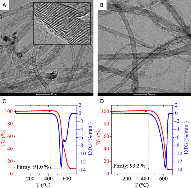
HRTEM images and the corresponding TG/DTG curves of the synthesized samples. N-doped CNT: (A), (C) and MWCNT: (B), (D).
Thermogravimetric measurements showed that the purity of the samples are 91 wt% and 93.2 wt% for N-BCNT and MWCNT, respectively (Fig. 2/C and 2/D). The initial ignition temperature of the N-BCNT sample was 424 °C, which is lower than in case of the MWCNT (438 °C). The remained metal or metal-oxide (primarily nickel) impurities can catalyze the thermal oxidation of carbons in the N-BCNT samples and could cause the lower ignition temperature (Li et al., 2008). Due to the synthetic procedure, a small amount of metal particles always remain inside the nanotubes, and these can not be efficiently removed from the system. Furthermore, the crystallinity of MWCNT is higher than in the case of the N-BCNT, thus it is more difficult to oxidize (Lehman et al., 2011). The oxygen containing functional groups on the nanotubes, and defects on the crystal structure of CNTs can also contribute to the lower ignition temperature (Feng et al., 2008; Bom et al., 2002).
The type of the bands of the incorporated nitrogen atoms in the structure of N-doped CNTs were examined by X-ray photoelectronsectroscopy (see Fig. 3). On the deconvoluted N 1s band the pyridinic and graphitic nitrogens can be identified at 398.4 eV and 401.2 eV binding energy, respectively. Oxidized nitrogens and shake-up satellite can also be found as the corresponding peaks show on the spectrum at 404.9 eV and above 410 eV, respectively.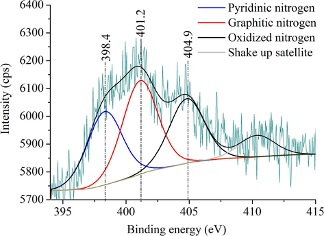
XPS spectrum with the deconvoluted N 1s band of the N-doped CNTs.
3.2 Characterization of N-BCNT and MWCNT filled PVC samples
The PVC resin (Ongrovil S-5070) which is used as polymer matrix in the experiments has a hierarchical supramolecular structure and it contains highly porous grains (Fig. 4/A). By sonochemical treatment of the PVC/CNT mixture, the N-BCNTs were dispersed into the PVC matrix. On the micrograph clearly visible that nanotubes cover the surface of the PVC grains (Fig. 4/B). Furthermore, an N-BCNT containing grain was cut and it can be seen that nanotubes are visible on the surface of the slice as well (Fig. 4/C). Apparently, the N-BCNTs were able to enter into the pores of the PVC granules.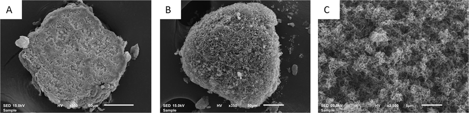
Microstructure of the pure (A) and N-BCNT containing (B and C) PVC composites. Surface slice of pure PVC grain (no nanotubes) (A); PVC/N-BCNT mixture (5% carbon nanotube) after ultrasonication (B); surface of the sliced N-BCNT containing sample (C).
CNT/PVC composites were prepared using the so called conventional method and a new method which involves ultrasonic treatment (Fig. 5). The filling of the CNT into PVC matrix was unsuccessful by the conventional method (Fig. 5A and C). The ultrasonic impregnation based new method facilitates the dispersion of the nanotubes in the PVC matrix and led to homogeneous N-BCNT and MWCNT filled PVC fibers (Fig. 5B and D).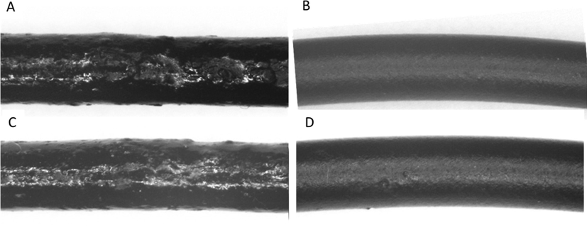
Extruded N-BCNT/PVC fibers produced by using the conventional (A) and the new ultrasonic method (B). MWCNT/PVC fibers produced by using the conventional (C) and the new ultrasonic method (D). The diameter of the extrudates is about 2 mm.
The presence and orientation of carbon nanotubes in the polimer matrix was determined by scanning electron microscopy (SEM). The polimer coated nanotubes are clearly visible and the PVC coating on the tube surface can be seen (Fig. 6). The dispersibility of the carbon nanotubes is high in the PVC matrix.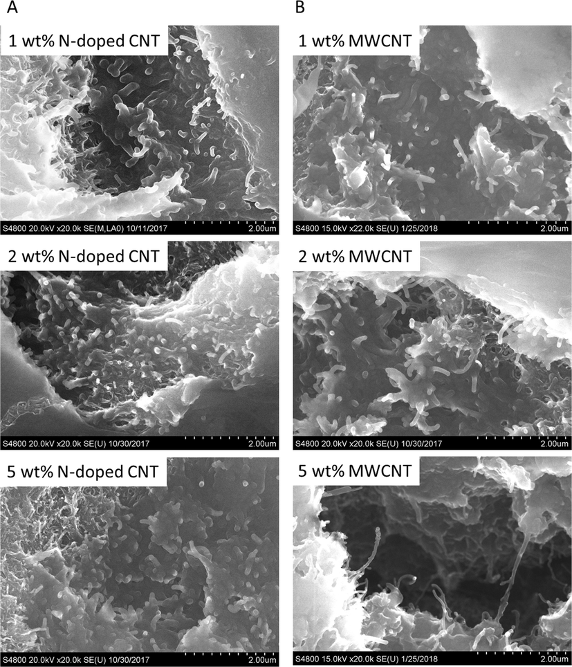
SEM images of the prepared N-BCNT/PVC (A) and MWCNT/PVC (B) composites.
3.3 Mechanical tests of the N-BCNT and MWCNT filled PVC samples
Mechanical testing of the composite samples was carried out on fiber specimens produced with extrusion. 3–3 different concentrations (1, 2 and 5%, respectively) of the nanotubes were used to produce the samples. Tensile testing on the samples were carried out using an Instron 5566 universal materials tester with a fiber clamper, and a rate of deformation of 20 mm/min at room temperature.
It can be seen from the stress-strain curves that the PVC composite which contains 5 wt% CNT exhibit higher tensile strength than the neat PVC, implying that the presence of the carbon nanotubes can remarkably improve mechanical strength of the composites (Fig. 7). The reinforcement effect is much larger in case of the N-doped CNTs, than the MWCNTs, with 5% loading. Such remarkable reinforcement of the N-CNT/PVC composites is mainly attributed to their high mechanical strength and the extraordinary structure, homogenous dispersibility of the N-doped CNT and good compatibility between PVC matrix and nitrogen doped carbon nanotubes. These features are beneficial to effectively transferring load between N-doped CNT and the PVC matrix in the tensile process and consequently resulting in high mechanical strength of these nano-composites.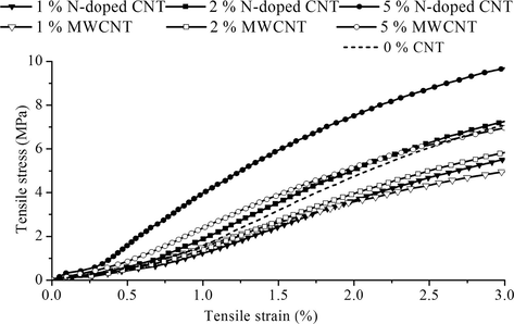
Tensile strain vs tensile stress diagram of the two different nanotube (N-doped CNT and MWCNT)/PVC composites.
As it can be expected, the results of the elongation versus filler loading (Fig. 8/A) shows a continuous decrease in elongation at break, as the filler nanotubes are having a much more rigid structure than the matrix polymer.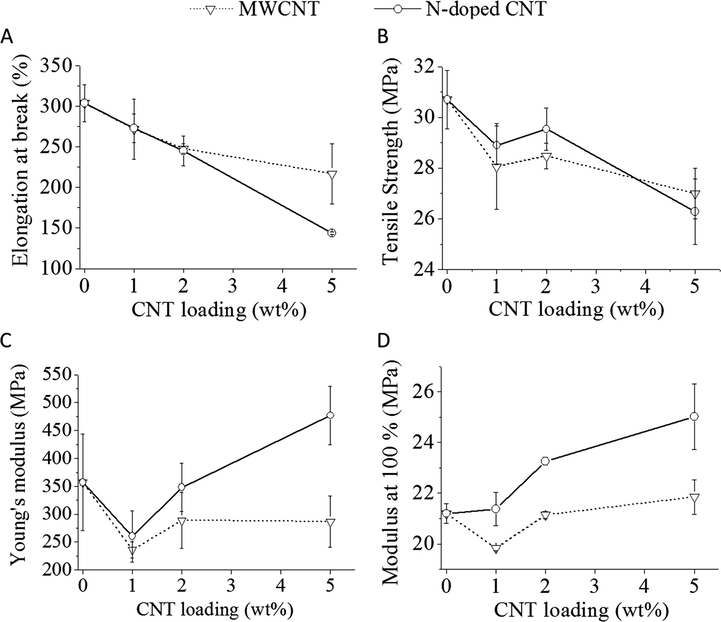
Elongation at break (A), tensile strength (B), Young’s modulus (C), and the tensile stress at modulus 100% (D) of the two different nanotube (N-doped CNT and MWCNT)/PVC composites.
For the tensile strength (Fig. 8/B), Young’s modulus (Fig. 8/C) and the modulus at 100% (Fig. 8/D) a small decrease can be seen initially (1 wt% CNT) compare to the neat PVC, which can indicate a not ideal interaction and structure formation. But as the filler content increases the modulus also start to increase, and the effect is larger in the case of N-BCNTs. For the tensile strength, a local maximum can be identified with increasing filler content at about 2% by weight and it is also clear that the change is more significant for the N-BCNT filled samples. The fact that there is an optimal CNT concentration and the strength decreases below and above it, might indicate a limited compatibility of the nanotubes with the matrix PVC.
MWCNT and PVC is less compatible than N-BCNT and PVC, as the MWCNT has a smaller effect in all cases. The maximum achieveable tensile strength needs further testing which can also help evaluating the ideal mixing ratio between the polymer and the filler, and shed light on the compatibility of the two compounds. The modified N-doped CNT is a good basis for improved compatibilty CNT/PVC composites.
4 Conclusion
Nitrogen-doped bamboo-shaped carbon nanotubes (N-BCNT) and non-doped multiwalled carbon nanotubes (MWCNT) were synthesized by the CCVD method. The structural differences were defined using high-resolution transmission electron microscopy (HRTEM) and the extraordinary structure of N-BCNT was visualized. The presence and orientation of carbon nanotubes in the polymer matrix was determined. The PVC polymer coated nanotubes are clearly visible and the SEM images confirmed that the dispersibility of the carbon nanotubes is high in the PVC matrix.
The graphene edges which can be found in the N-BCNT are missing in the case of MWCNT. The absence of this structural feature leads to a weaker interaction between the MWCNT and PVC matrix. In case of the N-BCNT/PVC composite the measured young modulus was 39.7% higher, while the elongation at brake decreased by 33.6% compare to the MWCNT/PVC composite. All in all, the N-BCNT/PVC composite was stronger than the MWCNT/PVC sample and thus, the N-doped CNT is more efficient reinforcing material, than its multiwalled counterpart.
Acknowledgement
The authors are grateful for the technical assistance of the Wanhua-BorsodChem Ltd. in roll-milling, extrusion and SEM microscopy on PVC grains. This research was supported by the European Union and the Hungarian State, co-financed by the European Regional Development Fund in the framework of the GINOP-2.3.4-15-2016-00004 project, aimed to promote the cooperation between the higher education and the industry. Emőke Sikora thanks the financial support by the ÚNKP-17-1 New National Excellence Program of the Ministry of Human Capacities (HU).
Data availability
Data will be made available on request.
References
- Effect of synthesis catalyst on structure of nitrogen-doped carbon nanotubes and electrical conductivity and electromagnetic interference shielding of their polymeric nanocomposites. Carbon N Y. 2016;98:358-372.
- [CrossRef] [Google Scholar]
- Microstructure and properties of polypropylene/carbon nanotube nanocomposites. Materials (Basel). 2010;3:2884-2946.
- [CrossRef] [Google Scholar]
- Thermogravimetric analysis of the oxidation of multiwalled carbon nanotubes: evidence for the role of defect sites in carbon nanotube chemistry. Nano Lett.. 2002;2:615-619.
- [CrossRef] [Google Scholar]
- Nanocomposites of poly(vinyl chloride) with carbon nanotubes (CNT) Compos. Sci. Technol.. 2007;67:890-894.
- [CrossRef] [Google Scholar]
- Evaluation of mechanical properties of functionalized carbon nanotube reinforced PMMA polymer nanocomposite. Karbala Int. J. Mod. Sci.. 2018;4:207-215.
- [CrossRef] [Google Scholar]
- Room temperature purification of few-walled carbon nanotubes with high yield. ACS Nano. 2008;2:1634-1638.
- [CrossRef] [Google Scholar]
- Tensile properties, morphology, and thermal behavior of PVC composites containing pine flour and bamboo flour. J. Appl. Polym. Sci.. 2004;93:1804-1811.
- [CrossRef] [Google Scholar]
- Surface modification of carbon nanotubes using 3-aminopropyltriethoxysilane to improve mechanical properties of nanocomposite based polymer matrix: experimental and density functional theory study. Appl. Surf. Sci.. 2017;420:167-179.
- [CrossRef] [Google Scholar]
- Enhancement of the thermo-mechanical properties and efficacy of mixing technique in the preparation of graphene/PVC nanocomposites compared to carbon nanotubes/PVC. Prog. Nat. Sci. Mater. Int.. 2014;24:579-587.
- [CrossRef] [Google Scholar]
- Fusion of particulate structure in polyvinyl chloride during powder extrusion. Polym. Eng. Sci.. 1972;12:199-203.
- [CrossRef] [Google Scholar]
- Fabrication of mixed matrix heterogeneous ion exchange membrane by multiwalled carbon nanotubes: electrochemical characterization and transport properties of mono and bivalent cations. Desalination. 2013;329:62-67.
- [CrossRef] [Google Scholar]
- Electrical and tensile properties of carbon black reinforced polyvinyl chloride conductive composites. C – J. Carbon Res.. 2018;4:15.
- [CrossRef] [Google Scholar]
- Evaluating the characteristics of multiwall carbon nanotubes. Carbon N Y. 2011;49:2581-2602.
- [CrossRef] [Google Scholar]
- Thermogravimetric analysis and TEM characterization of the oxidation and defect sites of carbon nanotubes synthesized by CVD of methane. Mater. Sci. Eng., A. 2008;473:355-359.
- [CrossRef] [Google Scholar]
- Tensile and impact properties of hollow glass bead-filled PVC composites. Macromol. Mater. Eng.. 2002;287:588-591.
- [CrossRef] [Google Scholar]
- Cell morphology and property relationships of microcellular foamed pvc/wood-fiber composites. Polym. Eng. Sci.. 1998;38:1862-1872.
- [CrossRef] [Google Scholar]
- Boron- and nitrogen-doped carbon nanotubes and graphene. Inorg. Chim. Acta. 2010;363:4163-4174.
- [CrossRef] [Google Scholar]
- Poly(vinyl chloride)-paste/clay nanocomposites: investigation of thermal and morphological characteristics. Polym. Degrad. Stab.. 2006;91:3322-3329.
- [CrossRef] [Google Scholar]
- Interfacial structures and mechanical properties of PVC composites reinforced by CaCO3 with different particle sizes and surface treatments. Polym. Int.. 2006;55:158-164.
- [CrossRef] [Google Scholar]
- Flexible conductive graphene/poly(vinyl chloride) composite thin films with high mechanical strength and thermal stability. Carbon N Y. 2011;49:198-205.
- [CrossRef] [Google Scholar]
- Electrical and mechanical properties of antistatic PVC films containing multi-layer graphene. Compos. Part B Eng.. 2015;79:444-450.
- [CrossRef] [Google Scholar]


