

Translate this page into:
Pollutants degradation and power generation by photocatalytic fuel cells: A comprehensive review
⁎Corresponding author. mousavi@unicamp.br (Amin Mousavi Khaneghah)
⁎⁎Co-corresponding author. mahfooz60@gamil.com (Masoud Moradi),
-
Received: ,
Accepted: ,
This article was originally published by Elsevier and was migrated to Scientific Scholar after the change of Publisher.
Peer review under responsibility of King Saud University.
Abstract
Schematic of pollutants degradation in PFC.
Abstract
Wastewater contains organic compounds (fatty acids, amino acids, and carbohydrates) that have a significant amount of chemical energy. In this regard, the use of wastewater for recovering energy by some appropriate energy conversion technologies can be considered as an appropriate approach to simultaneously achieve the reduction of environmental contamination and increasing supply of energy. The Photocatalytic Fuel Cell (PFC) can provide a new approach in developing technology for simultaneous organic pollutants removal from wastewaters and power generation, but it also has disadvantages, such as requires higher voltage, more cost and complexity. To present a comprehensive vision of the current state of the art, and progress the treatment efficiency and agitate new studies in these fields, this review discussed the study covering PFC aspects, with a focus on the comparison of pollutant degradation, power generation, different photoanode and photocathode materials as well as the application of the Fenton process in PFCs.
Keywords
Photocatalytic fuel cells
Pollutant degradation
Power generation
Photocatalysis

1 Introduction
Conventional water and wastewater treatment processes are not effective in removing and/or degrading a number of pollutants, as well as, some efficient treatment techniques e.g. reverse osmosis (RO) usually require high energy consumption for purification (for example, 5–100 kwh/kgCOD) (Li et al., 2019). An efficient solution to overcome this challenge is to add an additional unit of advanced oxidation processes (AOPs) to conventional water treatment equipment (Liu et al., 2019; Liu et al., 2017). AOPs are widely used to decompose several organic substances to highly reactive chemicals (Khatri et al., 2018; Vasseghian and Dragoi, 2018; Vasseghian et al., 2020). Among them, semiconductor-based photocatalytic processes have been widely welcomed as an efficient option due to their eligible properties such as high efficiency, low cost, high stability, low toxicity and chemical inertness (Sarac et al., 2020; Wang et al., 2019). The low level of rich chemical energy obtained during the process of elimination from organic decomposition is one of the main disadvantages of most AOPs (Jiang et al., 2018; Pirsaheb et al., 2019; Wang et al., 2019). On the other hand, the organic compounds in sewerage can be used as sources of carbon and energy that can be applied. Thus, It is essential to extend sustainable methods that can degrade these organic contaminants and synchronous recover their chemical energy (Li et al., 2019; Li et al., 2017). The Photocatalytic Fuel Cell (PFC) is a successful scheme for wastewater treatment and synchronous recovery of chemical energy from the wastewater (Lee et al., 2018). The non-selective properties of the photocatalyst lead to the degradation of an extensive range of pollutants such as dyes (Nordin et al., 2019; Lee et al., 2018; Ong et al., 2019; Khalik et al., 2017; Tang et al., 2019), antibiotics (Li et al., 2019; Zhao et al., 2017; Deng et al., 2018; Lu et al., 2019), heavy metal ions (Wang et al., 2017), alcoholic compounds (Xia et al., 2016; Sfaelou et al., 2014). However, a high similarity between PFC and other fuel cells (FC) types (such as microbial FC- MFC- (Fang et al., 2016); direct methanol FC (Wu et al., 2017), proton exchange membrane FC (Qi et al., 2018); alkaline polymer electrolyte membrane FC (Lan et al., 2015), can be observed. While this technique is able to simultaneously degrade organic pollutants from the wastewater and produce power (Khalik et al., 2017).
Compared to conventional MFCs, PFCs have the following desirable features, but may not be limited to: (i) PFC can use sunlight as an energy source and lead to the fast generation and direct transfer of electrons, thus increasing the degradation efficiency of pollutants; (ii) It is possible to design high-performance electromaterials for PFC by nanotechnology; (iii) PFC can be easily fabricated and operated in finite reaction conditions by controlling the light input; and (iv) PFC system has strong oxidative ability of photogenerated holes and •OH by non-selective oxidation of substrates (Li et al., 2019; Kee et al., 2018).
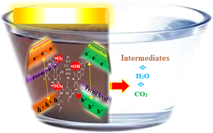
The PFC needs a photoanode carrying photocatalyst and light radiation (LR) to generate electrons (e−) to decompose organic pollutants and generate power (Eq. (1)). In order to ensure that the e− are excited in the conduction band (CB) and that they can leave the holes (h+) in the valence band (VB), the radiation energy should be higher or equal to the photocatalyst energy band. The UV irradiation of the anode detaches the photogenerated e− and h+ (Eqs. (2) and (3)). For power generation, due to the organic compounds’ decomposition in the anode, e− are provided and transmitted to the cathode by means of an external circuit (Eq. (4)). The hydrogen ions generated by the photooxidation process are transferred to the cathode by diffusion using a proton exchange membrane (PEM). Oxygen is provided at the cathode and the transferred e− react with O2, thus resulting in water (Eqs. (5)–(10)) or superoxide radicals (Eqs. (12) and (13)) (Lee et al., 2018).
Photoexcitation of photocatalyst:
Generation of •OH
Redox reactions
Generation of superoxides:
Significantly, most species of PFC reactions occur mainly on the surfaces of the electrodes. Additionally, in the solution, the reaction time is limited by the partly mass transfer and thus, the processing time is delayed. Consequently, in order to raise the efficiency of reactivity of materials and improve the mass transfer in the liquid phase, the PFC is commonly used in combination with materials such as carbon nanotubes (Das et al., 2017); graphene (Xiang et al., 2012) and metal oxides (Martin et al., 2015). TiO2, as one of the most important photocatalytic materials, is mainly employed due to high stability (physical and chemical) and unique properties (optical and electronic), easy to prepare, low cost and non-toxic (Li et al., 2014; Khataee et al., 2014). However, the fast recombination e−CB and h+ in TiO2 reduces the efficiency of photocatalytic degradation (Mousavi et al., 2020; Ying et al., 2016). In this regard, some new anodes have been introduced to raise the absorption capacity of radiation and e−- h+ separation on the photoelectrode surface (Table 1).
Authors/Year
Type of anodes
Characteristics of the PFCs
Substrates
Light source
Maximum power density (Pmax, W m−2)
Type of electrolyte
Effective photo-electrodes surface area (cm2)
Refs.
Antoniadou et al./2011
CdS/ZnS/ TiO2
PFC was manufactured from two rectangular compartments, filled with aerated electrolyte and separated by a silica frit. Both compartments included the same. UVA agitation of the anode was done by Black Light fluorescent tubes. An array of parallel tubes (each of 4 W nominal power) was set in front of the cell window, generating around 4.0 mW/cm2 of light on the titania film. The excitation was generated by a Xe lamp that simulated solar radiation. In all cases, glass-FTO electrode as a window passes the exciting irradiation through itself.
–
Ultraviolet A (UVA)
–
NaOH
0.5
(Antoniadou et al., 2011)
Liu et al. /2016
Ag/AgCl/GO
The PFC system had two photo-electrodes, a LED lamp (2 W) as a visible light source and an irradiation surface of 20 mm × 50 mm. The cell in a quartz tube (30 mm × 18 cm) had an aeration device, Ag/AgCl/GO-based anode and ZnIn2S4-based cathode placed at 2.5 cm from one-another. When the system was running, a 1 U resistance connected the anode.
Rhodamine B
Visible light
0.540
Na2SO4
-
(Liu et al., 2016)
Xie and Ouyang/2017
WO3/FTO
The 2 × 2 cm2 WO3/FTO anode with an effective area of 3.0 cm2 was fixed by an electrode holder and collected with the air-breathing cathode (3.0 cm diameter and 7.1 cm2 effective area) through copper wire. The distance between the anode and cathode was ∼ 2 cm. The Pt/C catalyst loaded side of the air-breathing cathode was in direct contact with the electrolyte and the other side (without the catalyst) was exposed to air.
Oxytetracycline hydrochloride
Simulated solar light
0.363
Na2SO4
3.0 (anode), 7.1 (cathode)
(Xie and Ouyang, 2017)
Lee et al./2017
ZnO/Zn
The system had an immobilized ZnO/Zn anode and a Pt/C cathode, placed at 5 cm from each other. An ultraviolet A (UVA) lamp was place at 15 cm from the anode represented the light source. Aeration was supplied at the cathode side.
Reactive Green 19
Ultraviolet A (UVA)
0.102
Without adding any supporting electrolyte
15
(Lee et al., 2017)
Xie et al./2017
ZnFe2O4/ TiO2-NTs
The system has 2 × 2 cm2 ZnFe2O4/TiO2-NTs anode (3.0 cm2 effective area) and an air-breathing cathode (3.0 cm diameter and 7.1 cm2 effective area) placed at ∼2 cm from each other. An electrode holder fixed the anode that was connected with the air-breathing cathode using copper wire. The Pt/C catalyst side of the air-breathing cathode was in direct contact with the electrolyte and the other side was exposed to the air (to receive oxygen from the surrounding environment). A 300 W Xe lamp with an AM 1.5 filter simulated the solar light.
Phenolic compounds and pharmaceutical products
Simulated solar light
0.013
Na2SO4
3.0 (anode), 7.1 (cathode)
(Xie et al., 2017)
Zeng et al. /2018
TiO2/WO3/W
The PFC was constructed using a dual-electrode configuration. The PFC was equipped an AM 1.5 illumination and 1 cm2 illumination area for both the WO3/TiO2 anode and Pt/BJS cathode.
Atrazine
Visible light
0.563
K2SO4
–
(Zeng et al., 2018)
Ye et al. /2018
TiO2 nanotube array (TNA)
The system had a TNA electrode (3 cm × 3 cm) as photoactive anode and a copper foil (Grade M2, 3 cm × 4.5 cm) as counter electrode placed at 2 cm from each other. The reaction cell (6 cm × 6 cm × 6 cm) is a rectangular quartz cube. A 450 mW UV-LED lamp (365 nm peak intensity) placed outside the reaction cell (on the side of TNA anode) generated 11.6 mW/cm2 radiant power at the TNA surface.
Micropollutant 4-chloro-2-methylphenoxyacetic acid
UV
–
Na2SO4
9.0
(Ye et al., 2018)
Ong et al./2019
ZnO/BaTiO3
An anode and platinum-loaded carbon (Pt/C) cathode (connected by a 1 kΩ resistivity external circuit) were placed in a 1000 ml Pyrex glass cell filled with 500 ml of RR120. Two ultraviolet A (UVA) lamps (placed at 100 mm from the anode and cathode) were used as the light source.
Reactive Red 120
Ultraviolet A (UVA)
0.005284
Without adding any supporting electrolyte
–
(Ong et al., 2019)
In this context, an overview of photocatalytic fuel cells for the degradation of pollutants and simultaneous power generation is presented. The effect of different photoanode and photocathode materials on pollutant degradation and power generation were discussed. To better understand the Fenton process on photocatalytic fuel cell systems, an analysis regarding the hybrid system of Fenton process and photocatalytic fuel cell for pollutant degradation and power generation was also performed.
2 Pollutant degradation
The water pollution crisis is one of the environmental problems generated by the development among human’ life. Discharging wastewater with organic pollutants such as dye (Iqbal et al., 2017; Mousavi et al., 2020; Xie et al., 2012; Yang et al., 2018) and antibiotics (Hailili et al., 2018; Osouleddini et al., 2019) are the most important segments of water pollution (Zarei et al., 2012). In this regard, recently some effective technologies were employed to reduce the toxic wastewater issue (Liu et al., 2016; Alikarami et al., 2019; Khataee et al., 2011). Among them, the PFC system has recently been approached as a promising technology to treat a wide range of colored wastewater (Katsumata et al., 2013).
Based on the PFC mechanism (Eqs. (1)–(13)), when the photoanode is irradiated by light, the e− are excited from VB into the CB (Eq. (1)). The band gap is also known as an energy gap and it will be further referred to as Eg. Then, it could react with the hydroxide ions or water molecules to produce the
(Eqs. (2) and (3)). Afterward, azo bonds are oxidized: i) directly, by photogenerated h+ (Eq. (4)); or ii) indirectly, by
(Eq. (5)). The e− move to the cathode and react with the hydrogen ions produced through photooxidation to water (Eq. (10)). In this process, the HO and O2– leads to photocatalytic degradation of organic contaminants (Fig. 1).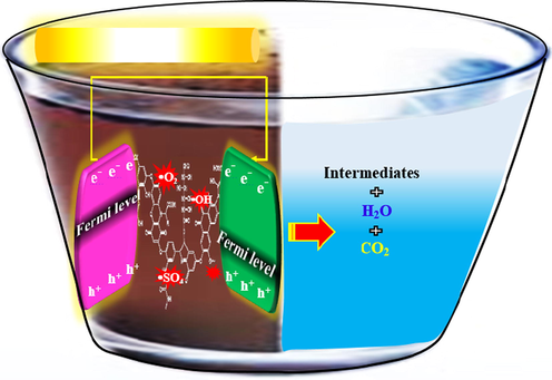
Schematic of pollutants degradation in PFC.
In the case of Methylene Blue (MB) degradation, Chen et al. utilized an aerated PFC with nanopore WO3/W photoanode and a Pt modified commercial silicon photovoltaic cell (Pt/PVC) photocathode (Chen et al., 2014). They were able to remove 14% of MB under the photolysis condition after 90 min and 91% of MB under aerated condition after 60 min. The Fermi level discrepancy between the two electrodes can make the e− to immigrate from photoanode to photocathode. Under aeration condition, the O2 molecules use the of Pt/PVC photocathode. To produce stable electricity in the external circuit, the h+ of Pt/PVC can catch the e− from WO3/W. Therefore, the WO3/W h+ can be generated by pollutants decomposition. According to the mentioned phenomena, in this system, the simultaneous recovery of energy and organic pollutant degradation can occur (Chen et al., 2014).
Tang et al. (Tang et al., 2014) (Tang et al., 2014) used a rotating disk PFC (RDPFC) that has as photoanode a TiO2/Ti disk. The system degrades RhB and Reactive Brilliant Red X-3B (RBR X-3B) and is formed by a Pt black/Pt cathode, NaOH anolyte, and H2SO4 catholyte. The proposed system had promising results, being practical to generate electricity and hydrogen (H2) energy under UV lighting and different types of dye wastewater. As the enhancement of dye concentration leads to a significant decrease of sample solution transmittance, the sample solution in the immersion reactor absorbs a high percentage of the ultraviolet light, thus leading to a low degradation efficiency; on the other hand, LR absorption by solution significantly decreased in the aqueous film RDPFC and retained efficiency with sensible performance and promising performance.
In another study, Wu et al. (Wu et al., 2015) (Wu et al., 2015) investigated the phenol removal efficiency using a PFC with TiO2 NRs/FTO photoanode, and C/Cu2O NWAs/Cu mesh photocathode. The system displays a remarkable performance for the degradation of phenol so that 84.2% TOC removal was achieved in 8 h. The reaction process in this study can be explained by Eqs. (14)–(18) (Wu et al., 2015). Moreover, the photoresponse of the photocatalyst and conductivity of the substrates can affect the PFC performance in pollutant degradation. Results indicated short circuit current (JSC) of TiO2 NRs/FTO PFC is far more than Jsc of TiO2 NTs/Ti PFC. The high value of JSC showed the PFC system has a synergistic facilitated impact on the photoresponse of the photoanode and photocathode. The Fermi level of TiO2NRs/FTO is further negative than that of C/Cu2O NWAs/Cu mesh, resulting in a self-driven PFC during solar LR. For this system, the residual photoanode h+ and the photocathode e− lead to simultaneous organic compound degradation and H2 generation (Xie et al., 2017).
Also, Yang et al. (Yang et al., 2015) (Yang et al., 2015) applied a dual-chamber rotating-disk PFC with TiO2 nanotube array/Ti (TNA/Ti) rotating-disk photoanode and Cu rotating-disk cathode for degradation RhB, RBR X-3B, MB, Bisphenol A (BPA), and Glucose. They succeeded to remove 96.8%, 69.8%, 92.9%, 86.9% and 93.2% of RhB, RBR X-3B, MB, Glucose, and RhB/BPA in anode chamber and 89.8%, 50.9%, 84.7%, 54.8% and 71.3% of RhB, RBR X-3B, MB, Glucose, and RhB/BPA in cathode chamber, respectively. The results revealed that the organic degradation process can be done in both the anode and cathode chamber with different pathway. Under UV irradiation the hole could be generated in the anode which leads to direct oxidation of the pollutant, Eqs. (19)–(21).
While both direct and indirect processes are involved in the pollutant degradation by cathode chamber as depicted in the following equations:
Direct pathway:
Indirect pathway:
To decompose the existing organic pollutants from water samples, the organic compounds represented the source of energy. It has a series of advantages that include: i) increased efficiency of LR utilization attained by a thin-film photocatalytic reaction and TNA photoanode; ii) more suitable h+–e− separation through the TNA microstructure; iii) enhanced mass transfer via electrodes rotation; and iv) in situ production of H2O2 and •OH (that simplifies the decomposition of organic compounds). The appropriate efficiency was ascribed to various decomposition pathways such as direct e− reduction, direct h+ oxidation, indirect •OH oxidation, and indirect H2O2 oxidation. The e− migration could produce usable electricity, a fact that represents an advantage over conventional PFCs (Zeng et al., 2018).
Bai et al. (Bai et al., 2016) (Ye et al., 2018) investigated Methyl Orange (MO), CR and MB removal efficiency by a PFC with BiVO4/TiO2nano-tubes/FTO photoanode and ZnO/CuO nanowires/FTO photocathode. They achieved to remove 76%, 83%, and 90% of MO, CR, and MB, respectively. The mechanism of pollutants degradation is due to this fact that the Fermi level of BiVO4/TiO2 is far more negative than ZnO/CuO which leads to migration of the he BiVO4/TiO2 e− and the ZnO/CuO h+ can be moved by an internal bias and then discharged to simultaneously recover energy and decompose organic compounds. On the other hand however, the photocathode electrons and photoanode holes would be released and contribute to the organic pollutants (Eqs. (27)–(29)). Moreover, the type of substrate affects the PFC performance so that PFC performed better in the presence of phenol and glucose. This can correspond to differences in the molecular structure of organic matter (Bai et al., 2016).
Furthermore, for the Reactive Green 19 (RG19) degradation, Lee et al. employed a PFC having a ZnO/Zn photoanode and platinum loaded carbon cathode. In this study, the effect of several inert electrolytes such as NaCl, Na2SO4, and MgSO4, aeration, and initial concentration of dye on performance was investigated. It was shown that NaCl inert electrolyte has the highest RG19 degradation efficiency (100% after 8 h) due to the direct reaction of NaCl with •OH generated on the surface of the ZnO Photoanode. On the other hand, hypochlorite ions could be produced from NaCl solution (Eqs. (30)–(32)) which leads to indirect oxidation of RG19 (Lee et al., 2016).
The addition of Na2SO4, NaCl, and MgSO4 as inert electrolytes lead to a high Jsc and Pmax. This can be explained by the fact that the conductivity of the media enhanced with the inert electrolyte leads to a decreased PFC internal resistance. Furthermore, the existence of chloride ions contributes to a direct, strong oxidation reaction at the anode surface that, as a result, enhances degradation. For MgSO4 and Na2SO4, due to the absence of chloride, the degradation rates were not as good as that of NaCl. Totally, the presence of supporting electrolyte significantly enhances the removal of color. Because the electrolyte causes increased the potential difference on the electrodes. This phenomenon facilitates the spontaneous flow of photogenerated electrons to the cathode and subsequent generation of oxidizing photogenerated holes in the valence band of the anode (Shen et al., 2006).
Initial concentration of the pollutant is the other factor that affects the PFC performance. The removal efficiency of RG19 was decreased with increasing of RG19 up to 30 mg/L. This due to prevent of UV transmission from the solution to the photoanode which leads to restricted availability of photon for •OH generation. On the other hand, the photoexcitation of photoanode can be decreased with increasing of initial concentration of RG19 (Saquib and Muneer, 2003; Saquib and Muneer, 2003).
RhB removal was also studied by Sui et al. (Sui et al., 2017), as a PFC equipped with a biocathode and TiO2 and Ag/TiO2 photoanodes was used. The anode was designed by doping Ag into the three-dimensional TiO2 nanoarrays formed on Ti mesh. A 99.5% removal rate was obtained with Ag/TiO2 photoanode and 97.3% with TiO2 photoanode. For both types of photoanode, the RhB removal followed pseudo-first-order kinetics. The photoanode made of Ag/TiO2 is significantly better (in terms of RhB decomposition and electricity production performance) than that made of TiO2.
After 90 min operation, Zhao et al. (Zhao et al., 2017) reported a removal rate of 91.98%, 98.57%, 92.36% and 68.09% for MO, MB, CR and Tetracycline (TC), respectively using a hybrid Fenton-PFC system with TiO2 TNA photoanode and the Pt/SiPVC photocathode. The degradation efficiency for these compounds in traditional PFC (without ferrous ions) was 53.61%, 45.38%, 51.09%, and 30.65%, respectively. The main reason for this increase can be correlated with the introduction of Fe2+ to the system which leads to an intensification of radical reactions and thus, the degradation efficiency increases (more details about this issue are provided in section 7).
Also, Zhao et al. (2017) (Zhao et al., 2017) proposed a system that increases organic decomposition and electricity generation concurrently by using Fe2+ ions to intensify the reaction of radicals. The system had TiO2 TNA photoanode and Pt-black/Pt photocathode and was used for degradation of MO, MB, Congo Red (CR), and TC. The degradation efficiency for MO, MB, CR, and TC in traditional PFC was 34.99%, 43.75%, 40.58%, and 34.40%, respectively, but after adding the ferrous ions to the system, the degradation efficiency for these compounds increased to 97.34%, 95.36%, 93.23%, and 73.80%, respectively. In addition, the process parameters (pH, electrolyte, Fe2+concentration) were evaluated.
The mechanism of pollutant degradation is assigned to hydroxyl radical via electron-hole pairs are generation during UV irradiation as presented in the Eqs. (33) and (34).
On the other hand, continuous current in the cathode leads to electrons reducing O2 which causes the generation of different reactive radicals Eqs. (35)–(38).
Also, the electrolyte concentration influence the PFC performance, so that increasing of sodium sulfate concentration from 0.00 mol/L to 0.10 mol/L cause the enhancement of color removal from 58.47% to 97.34%. This due to increasing of solution conductivity which leads to transmitted of photoinduced e− through the external circuit of the PFC (Zhao et al., 2017).
To remove RG19, Lee et al. (2018) (Lee et al., 2018) applied a membrane-less PFC with a photoanode made of ZnO loaded carbon and a cathode made of Pt loaded carbon. The effect of dissolved oxygen (DO) was investigated on the degradation efficiency and it was shown that because the DO maintains the e−- h+ pair separation of ZnO, the DO concentration increase leads to a rise of RG19 removal rate. It was also shown that the decolorization performance is 37% at a slow rate (k = 0.033 h−1), low DO concentration (roughly 0.2 mg L−1), and N2 gas for 8 h. Moreover, the e−, h+, •OH, O2•−, OO• and H2O2 are the main radicals which contribute in the dye degradation process (Eqs. (1)–(13)).
In another study, Li et al. (Li et al., 2018) applied a PFC coupling with persulfate (PS) activation TiO2 nanotube arrays on a titanium sheet as the photoanode to remove MO. The proposed system could enhance the reaction of photocatalytic MO removal using the formation of active species (SO4•− and •OH) from the solid electrodes surface to the total liquid phase. For this reason, PFC/PS represented significant cell efficiency, raising the MO degradation by 40.36% (compared to PFC without PS), reaching 90.19%. Furthermore, the MO degradation process conforms the pseudo-first-order kinetics model, the removal mechanism being described by Eqs. (39)–(47). In this connecting system, electricity production was higher by 44.97% than the bare PFC (Li et al., 2018).
In another study, Lu et al. (Lu et al., 2018) (Lu et al., 2018) applied a PFC with BiOBr/TiO2 TNAs with 5, 10, 15, and 20 consecutive ionic layer adsorption and reaction cycles photoanode and Pt cathode for RhB removal. Using this system, 99.7% of RhB was removed; the working mechanism is described by Eqs. (48)–(49) at the photoanode and Eqs. (50)–(51) at the photocathode.
At the photoanode,
At the cathode,
Besides, for the removal of Reactive Red 120 (RR120), Ong et al. (Ong et al., 2019) employed a PFC having as photoanode a ZnO/BaTiO3 loaded carbon plate heterojunction. This study confirmed that Z1B1/C/Z1B1 system has the highest dye removal efficiency (93.67%) due to sufficient ZnO loading into the Z1B3 system and excellent absorption of UV light. The Langmuir-Hinshelwood kinetics model illustrated a good agreement (R2 ≈ 1) between the kinetic model and the experimental data. The Z1B1/C/Z1B1system has the highest rate constant (0.3554 h−1) which shows the higher removal efficiency rate of the RR120 (Ong et al., 2019). However, the direct photolysis is dramatically slower than the other processes and has the lowest rate constant of aerated PFC system. The possible reactions for RR120 degradation are described in the following equations (Ong et al., 2019):
Photoanode
Cathode (in the presence of oxygen)
Li et al. (2019) (Li et al., 2019) investigated the effects of adding peroxymonosulfate (PMS) into a PFC with TiO2/Ti photoanode and Pt cathode on TC removal from aqueous solution. The results demonstrated that the addition of PMS could significantly enhance the TC decomposing and accelerate the reaction rate because it has a strong oxidative capacity and can inactivate part of TC. When PMS is activated in presence of UV irradiation (Eqs. (63) and (64)), the produced sulfate radical, •OH, singlet oxygen (1O2) and PMS direct oxidation can improve the TC degradation (Sharma et al., 2015; Chen et al., 2018; Yang et al., 2018). Furthermore, adding PMS to the PFC can play the role of sacrificial agent that reacts with e− (Eqs. (65) and (66)) (Sayed et al., 2017) and decreases the recombination of photogenerated e− and h+ on the photoanode, thus increasing the production of reactive radicals.
In summary, Table 2 illustrates a summary of the different works tackling the issue of pollutant degradation with various PFCs systems.
Authors/Year
Photoanodes
Photocathodes
Substrates
Degradation Efficiency (%)
Process Time (min)
Maximum power density (Pmax, W m−2)
Open circuit voltage (Voc, V)
Refs.
Chen et al./2012
WO3/W
Cu2O/Cu
Rhodamine B
63
300
0.677
0.33
(Chen et al., 2012)
Congo Red
74
Phenol
58
Chen et al./2014
nanopore WO3/W
Pt/PVC
Methylene Blue
91
90
1.33
0.38
(Chen et al., 2014)
Tang et al./2014
TiO2/Ti disk
Pt black/Pt electrode
Rhodamine B
≈ 100
240
5.049
0.953
(Tang et al., 2014)
Reactive Brilliant Red X-3B
≈ 100
6.788
0.978
Li et al./2014
TiO2/FTO
carbon paper deposited with carbon black and Pt black
Methylene Blue
83.9
360
5.80
1.06
(Li et al., 2014)
Wu et al./2015
TiO2 NRs/FTO
C/Cu2O NWAs/Cu mesh
Phenol
84.2 of TOC
480
7.3
0.41
(Wu et al., 2015)
Yang et al./2015
TiO2 nanotube array/Ti rotating-disk
Cu rotating-disk
Anode Chamber
Cathode Chamber
120
-
(Yang et al., 2015)
(Wu et al., 2015)
Rhodamine B
96.8
89.8
Reactive Brilliant Red X-3B
69.8
50.9
Methylene Blue
92.9
84.7
Glucose
86.9
54.8
Rhodamine B/ Bisphenol A
93.2
71.3
Bai et al./2016
BiVO4/TiO2nano-tubes/FTO
ZnO/CuO nanowires/FTO
Methyl Orange
76
80
1.16
0.53
(Bai et al., 2016)
Congo Red
83
Methylene Blue
90
Khalik et al./2016
ZnO onto carbon felt
Pt-coated carbon paper
Reactive Black 5
≈ 100
1440
3.35 (Na2SO4 electrolyte), 2.56 (MgSO4 electrolyte) and 2.45 (NaCl electrolyte)
1.129 (Na2SO4 electrolyte), 1.070 (MgSO4 electrolyte) and 1.100 (NaCl electrolyte)
(Khalik et al., 2016)
Lee et al./2016
ZnO/Zn
platinum loaded carbon
Reactive Green 19
100
480
12.696 (Na2SO4 electrolyte), 1.077 (MgSO4 electrolyte) and 2.817 (NaCl electrolyte)
1.128 (Na2SO4 electrolyte), 0.990 (MgSO4 electrolyte) and 1.049 (NaCl electrolyte)
(Lee et al., 2016)
Khalik et al./2017
ZnO/carbon felt
Pt-loaded carbon
Reactive Black 5
80
360
6.571 (UV) and 16.651 (solar)
0.75 (UV) and 0.82 (solar)
(Khalik et al., 2017)
Sui et al./2017
TiO2/Ti mesh
activated carbon/ poly tetra fluoro ethylene
Rhodamine B
98.5
150
0.222
-
(Sui et al., 2017)
Sui et al./2017
TiO2
biocathode with carbon fiber brushes
Rhodamine B
97.3
120
0.211
0.350
(Sui et al., 2017)
Ag/ TiO2
99.5
0.318
0.458
Zhao et al./2017
TiO2 TNA
Pt/SiPVC
Methyl Orange
91.98
90
0.84 (PFC) and 1.57 (PFC(Fe2+)
0.75 (PFC) and 0.76 (PFC(Fe2+)
(Zhao et al., 2017)
Methylene Blue
98.57
0.65 (PFC) and 1.01 (PFC(Fe2+)
0.82 (PFC) and 0.81 (PFC(Fe2+)
Congo Red
92.36
0.52 (PFC) and 1.24 (PFC(Fe2+)
0.84 (PFC) and 0.85 (PFC(Fe2+)
Tetracycline
68.09
0.48 (PFC) and 0.97 (PFC(Fe2+)
0.77 (PFC) and 0.81 (PFC(Fe2+)
Zhao et al./2017
TiO2 TNA
Pt-black/Pt
Methyl Orange
97.34
60
3.30 (PFC) and 5.70 (Fenton-PFC)
1.26 (PFC) and 1.23 (Fenton-PFC)
(Zhao et al., 2017)
Methylene Blue
95.36
2.70 (PFC) and 3.70 (Fenton-PFC)
1.26 (PFC) and 1.26 (Fenton-PFC)
Congo Red
93.23
3.00 (PFC) and 4.30 (Fenton-PFC)
1.25 (PFC) and 1.25 (Fenton-PFC)
Tetracycline
73.80
2.50 (PFC) and 3.40 (Fenton-PFC)
1.20 (PFC) and 1.21 (Fenton-PFC)
Lee et al./2018
ZnO loaded carbon
platinum loaded carbon
Reactive Green 19
37
480
0.0028
-
(Lee et al., 2018)
Lee et al./2018
immobilizing ZnO onto zinc
platinum loaded carbon
Reactive Green 19
93-sunlight
86-ultraviolet480
0.026 (sunlight) and 0.021 (ultraviolet)
0.704 (sunlight) and 0.814 (ultraviolet)
(Lee et al., 2018)
Acid Orange 7
62-sunlight
74-ultraviolet0.010 (sunlight) and 0.012 (ultraviolet)
0.669 (sunlight) and 0.683 (ultraviolet)
Methylene Blue
87-sunlight
36-ultraviolet0.032 (sunlight) and 0.017 (ultraviolet)
0.924 (sunlight) and 0.855 (ultraviolet)
Nahyoon et al./2018
Fe/GTiP
ZnIn2S4
Rhodamine B
79.5
100
–
0.4
(Nahyoon et al., 2018)
Li et al./2018
TiO2 TNA on the titanium sheet
platinum plate
Methyl Orange
92
240
0.110 (PFC) and 0.1925 (PFC/PS)
0.682 (PFC) and 0.856 (PFC/PS)
(Li et al., 2018)
Kee et al./2018
ZnO/Zn
CuO/Cu
Methyl Green
92
240
0.164 (Na2SO4 electrolyte), 0.142 (MgSO4 electrolyte), 0.159 (NaCl electrolyte) and 0.054 (No electrolyte)
0.919 (Na2SO4 electrolyte), 0.798 (MgSO4 electrolyte), 0.898 (NaCl electrolyte) and 0.702 (No electrolyte)
(Kee et al., 2018)
Lu et al./2018
BiOBr/TiO2 TNAs with 15 SILAR
Pt
Rhodamine B
99.7
240
0.022
0.498
(Lu et al., 2018)
Zeng et al./2018
TiO2/WO3/W
Pt/BJS
Rhodamine B
99.3
180
0.694
0.792
(Zeng et al., 2018)
Methylene Blue
98.6
0.588
0.768
Phenol
91.7
0.498
0.753
Bisphenol A
95.2
0.526
0.766
Dichlorophen
96.5
0.563
0.757
Tetracycline
92.3
0.554
0.772
Deng et al./2018
Ag-TiO2
Pt
4-chlorophenol
32.6
360
0.03398
0.492
(Deng et al., 2018)
Phenol
37.9
0.08995
0.499
Tetracycline
96.4
0.10212
0.499
Ong et al./2019
ZnO/BaTiO3loaded carbon plate heterojunction
Z1B1/C/Z1B1
Reactive Red 120
93.67
480
0.005284
0.35
(Ong et al., 2019)
Rabé et al./2019
Z-scheme g-C3N4/Fe0/TiO2
WO3
berberine chloride
91
90
16.4
0.8
(Rabé et al., 2019)
Li et al./2019
TiO2/Ti
platinum
Tetracycline
90.14
60
0.015 (PFC) and 0.034 (PFC/PMS)
0.587 (PFC) and 0.749 (PFC/PMS)
(Li et al., 2019)
Wang et al./2020
TiO2 nanorods
Cu2O
Formaldehyde
–
3.3
–
0.58
(Wang et al., 2020)
Yu et al./2020
Ag3PO4
Cu2O
Tetracycline
30
240
0.0416
0.095
(Yu et al., 2020)
g-C3N4
20.82
0.00067
0.080
Ag3PO4@g-C3N4
76
0.0606
0.18
Lam et al./2020
TiO2/ZnO/Zn
CuO/Cu
Escherichia coli
99
60
0.172
0.868
(Lam et al., 2020)
Chen et al./2020
TiO2 nanotube arrays
Pt
Ofloxacin
96.8
60
0.247
1.35
(Chen et al., 2020)
Lam et al./2020
ZnO/Zn
Pt
Sunset yellow
–
240
0.000565
0.411
(Lam et al., 2020)
Phenol
–
0.00031
0.398
WO3/ZnO/Zn
Sunset yellow
84.6
0.001052
0.823
Phenol
67.5
0.000574
0.759
Kee et al./2020
TiO2/ZnO/Zn
TiO2/CuO/Cu
Palm oil mill effluent treatment
90
240
0.734
1.173
(Kee et al., 2020)
Table 2. Degradation of different pollutants in PFCs (Chen et al., 2014; Wu et al., 2015; Tang et al., 2014; Yang et al., 2015; Bai et al., 2016; Chen et al., 2012; Li et al., 2014).
2.1 Bacteria inactivation
Real wastewater contains countless microorganisms and bacteria types that can threaten human health and environmental stability (Zhang et al., 2018). Because conventional disinfection processes e.g. chlorination have led to the generation of toxic byproducts (Ren et al., 2009), there has been a great interest in recent years in the promotion of photocatalysis for disinfection process. The first example of semiconductor photocatalysis used as a disinfection process was reported by Matsunaga et al. (Matsunaga et al., 1985). Since then, due to its safety, low cost and efficiency, the photocatalytic disinfectant TiO2 has been studied. However, its low quantum efficiency and absorption only near the UV region (400 nm) limit its practical application. So far, many efforts to increase the photocatalytic performance and use of visible light from TiO2 with rectification methods such as impurity doping, metallization, sensitivity and coating, to extend the edge of TiO2 adsorption to the optical region can be seen (Yu et al., 2005; Elahifard et al., 2007; Wang et al., 2019; Shanmugam et al., 2020). However, the correction processes are complex and the prepared samples usually suffer from disadvantages e.g. low stability. In recent years, the development of PFCs to inactivate bacteria has become such an important issue that the technology can use a combination of different nanomaterials for use in photocathodes and photododes to significant efficiencies to inactivate bacteria.
Lam et al. (2020) applied a PFC with TiO2/ZnO/Zn as anode and CuO/Cu as cathode for greywater and bacteria removal and simultaneous energy generation. They found that E. coli cells decreased significantly after 60 min process in PFC. Such efficient treatment efficiency of PFC was due to action of ROS, containing •O2–, •OH, H2O2, and h+ by anodic TiO2/ZnO/Zn, which could directly inactivate the bacterial cells.
3 Power generation
3.1 Electricity generation
Under LR, the e− and h+ of a semiconductor is separated and a photovoltage is created. The photo-generated h+ and e− are the major cause of oxidation and reduction in the n-type and p-type semiconductors, respectively (Zarei et al., 2012; Alikarami et al., 2019). The fuel used to feed a PFC can be either organic or inorganic and it is dissolved in the electrolyte of anode compartment (Ong et al., 2019; Lianos, 2017). The compounds with the CxHyOz structure (alcohols, diols, organic acids, and carbohydrates), usual products of biomass, are the most efficient organic fuels (Sfaelou and Lianos, 2016). In the system, as a sustainable green technology, it is capable of decomposing organic pollutants and producing electricity simultaneously (Sui et al., 2017) as LR of photocatalytic sites of photoanode in a certain range of wavelengths led to the production of e−-h+ pairs (Zhao et al., 2017; Zeng et al., 2018; Xia et al., 2016) (Fig. 2). However, in order to ensure that the photogenerated e− would be excited from the photocatalyst VB to the CB, light energy (
than the photocatalyst Eg) is required. The h+, which have strong oxidability to decompose different organics, react with the organic pollutants to oxidize and degrade them to CO2, e− and protons (CxHyOz + •OH → CO2 + H+ + e−) (Lee et al., 2018; Khalik et al., 2017). At this time, , the e−generated from photocatalysis and oxidation of organics at the photoanode side are transferred to the cathode side, generating electricity (Xie and Ouyang, 2017; Xia et al., 2016).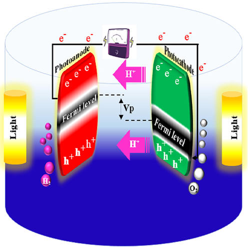
Electricity generation and hydrogen production in PFC.
It is noteworthy that organic fuel oxidation, or an inorganic sacrificial agent (such as S−2, SO3−2,…) or H2O itself leads to the electricity generation and H2 production, while electricity alone is generated in the presence of O2 (Lianos, 2017). Indeed, a PFC can operate in two main operation manners: electricity or H2. production In the absence of O2, PFC produces molecular H2 either by protons reduction (at acidic pH) or by water reduction (at alkaline pH) (Sfaelou and Lianos, 2016). The potential discrepancy between the Fermi levels of two electrodes creates the driving force that causes e− transfer from photoanode to the cathode. For practical aims, the function of the cell can be approximated using the following strategies. The photoanode potential for n-type semiconductor photocatalysts is close to the CB potential (Lianos, 2017).
For the cell efficiency evolution, the first aspect considered is the estimation of produced e− number as a percentage of absorbed photons. This is indicated by the incident photon-to-e− conversion efficiency (IPCE) value. It can be calculated by the Eq. (67) (Lianos, 2011; Varghese and Grimes, 2008):
Another parameter used to express the PFC efficiency is the Fill factor (FF). It is computed using Eq. (68) (O'regan and Grätzel, 1991):
The next parameter employed for all types of fuel cells is power density. The generated power per unit anode area is calculated by Eq. (69) (Lee et al., 2016).
In the case of PFC performance for the degradation of pollutants, a parameter called degradation efficiency or removal efficiency is applied. It is estimated by the Eq. (70) (Li et al., 2019):
Many studies focused on improving different aspects of a PFC. For example, a hybrid system of PFC-peroxi-coagulation (PFC-PC) was introduced to decompose organic pollutants and to simultaneously produce electricity (Nordin et al., 2019). In this hybrid system, three forms of photocatalysts (TiO2, ZnO, and α-Fe2O3 immobilized on carbon_cloth –CC-) were employed asphotoanodes and degradation of Amaranth dye (93.8%) were obtained (Nordin et al., 2019). Most of the research (Chen et al., 2012; Xia et al., 2016; Liu et al., 2011; Li et al., 2013; Li et al., 2015; Yang et al., 2014) was focused on the operating parameters and optimal performance. The Ho research group reported the effect of different DO concentrations on the mechanism of electricity generation and dye degradation (diazo dye RG19) in the single-chambered PFC based on ZnO/C photoanode (Lee et al., 2018). RG19 has a high resistance to microbial and chemical decomposition (Zuorro and Roberto, 2014). However, the RG19 degradation rate and the electricity generation was raised under high DO concentration (Wang et al., 2019). In all the previous studies, the used systems are single photoelectrode PFC consisting of one photoelectrode (photoanode). It should be noted that systems with dual photoelectrodes of photoanode and photocathode were also proposed (Liu et al., 2016; Bai et al., 2016; Chen et al., 2012; Pan et al., 2018). A dual photoelectrode PFC is formed from an n-type semiconductor photoanode and p-type photocathode. Under light/UV radiation, both photoelectrodes can produce e−- h+ pairs. The more negative Fermi level of the photoanode compared to the photocathode forms a bias that led to the e− migration from the photoanode via the external circuit incorporated into the photocathode h+ (Wu et al., 2015; Chen et al., 2012). The accumulation of h+ occurs on the photoanode and of e− on the photocathode; therefore, it is a Z-scheme (Tada et al., 2006; Maeda, 2013; Zhou et al., 2014).
3.2 Hydrogen generation
As we know, solar energy can be turned into useful forms of energy (electricity or chemical energy) using photoelectrochemical cells (PECs). Since the (Fujishima and Kenichi, 1972) paper, the H2 generation through photocatalysis has been the topic of exhaustive studies. In fact, one way to store energy is to convert solar into chemical energy, particularly H2. The photoelectrochemical conversion of solar energy provides the most promising routes for this purpose (Sfaelou and Lianos, 2016; Darbandi et al., 2019). Because of its zero carbon emission, high heat combustion, high energy capacity per unit volume, simple generation and on-site storage, hydrogen is considered a key clean energy option (Veziroǧlu, 2008; Ruiz-Gómez, 2013; Kelly and Thomas, 2008). As any standard PEC, oxidation_half-reaction on the photoanode of PFC is balanced by reduction_half-reaction on the cathode. The reduction_half-reaction does not originally depend on the organic fuel type or inorganic sacrificial agent but it is a standard reaction affected merely by pH and O2 (Sfaelou and Lianos, 2016; Michal et al., 2014; Papagiannis et al., 2020). Therefore, oxidation half-reaction (71) is balanced by either half-reaction (72) or (73) (depending on if there is an inert environment or O2 is present) (Lianos, 2017) (Fig. 2).
The overall reaction becomes Eq. (74) (Lianos, 2017); which is consistent with photo electrocatalytic reforming for hydrogen production (Chiarello et al., 2010; Nomikos et al., 2014).
For hydrogen generation, the efficiency of solar to H2 (ηSTH) is determined as (Li et al., 2013; Kim et al., 2016):
In reality, ηSTH represents the device efficiency and indicates its current generation capacity. However, the H2 generation is not guaranteed by the flow of current and the ηSTH determination should be accompanied by faradaic efficiency calculation (the percentage of current converted into H2) (Lianos, 2017):
Furthermore, as discussed in Section 3.1, a new application of PFC was introduced for H2 generation by a solar-driven dual-photoelectrode PFC (Wu et al., 2015). To design such a system, with the aim of simultaneously generating electricity and hydrogen, the photoanode should be an n-type semiconductor and have a good photocatalytic activity (Wu et al., 2015). The photocathode should be a p-type semiconductor whose Ecb (vs. NHE) should be more negative than 0 V ( ) for the purpose of hydrogen generation, such as Cu2O (Wang et al., 2013; Huang et al., 2011).
4 Photoanodes
4.1 The effects of different photoanode materials
Considering that the photoanode plays a significant role, the researchers try to reduce the photoanode limitations by improving the photocurrent and VLR response and decreasing the cost of construction and practical applications (Venkatkarthick et al., 2017; Venkatkarthick et al., 2016). Moreover, the fast induced e− and recombination of e−-h+ pairs in the_photoanode would limit the photoelectrochemical_reaction (Khataee et al., 2011), the Eg and the recombination of photogenerated e−and h+ are two main parameters that affect the photocatalytic activity to produce •OH and electricity (Ong et al., 2018) (Fig. 3).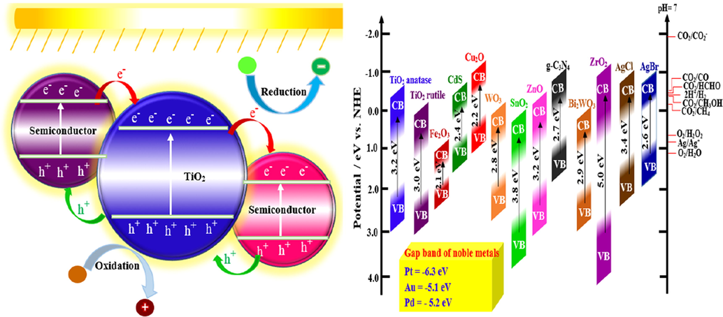
Reduction/oxidation mechanism in photocatalytic reactions and gap band of some semiconductors which used in photoanode and photocathode of PFC.
Accordingly, the photoanode_material with different Eg, recombination rate and features of e− mobility play a fundamental role in the PFC systems, which can affect their performance. For these, numerous photoanode such as TiO2, ZnO, WO3, α-Fe2O3, BiVO4, BaTiO3 have been studied so far (Ong et al., 2019; Strataki et al., 2010; Monfort et al., 2016; Gan et al., 2014; Horiuchi et al., 2013; Bhatt and Lee, 2015; Pop et al., 2015; Gao et al., 2014; Alexander et al., 2008). Based on a recent review (Lianos, 2017), most studies on the_PFC to date are focused on TiO2_photoanode. Usually, the Degussa P25 TiO2 powder (UV activated) is the commercially accessible photocatalyst used for the PFC photoanode (Kaneko et al., 2006; Seger et al., 2012; Antoniadou and Lianos, 2010). TiO2 has raised an excessive interest as photocatalyst among semiconductors and, since it possesses stable physical and chemical features such as low cost, easy to prepare, nontoxicity, outstanding stability, and excellent electronic and optical properties (Li et al., 2014; Liu et al., 2011). For instance, Kaneko et al. (Kaneko et al., 2006) used a nanoporous titanium dioxide film_photoanode and an O2-reducing cathode to construct a PFC. Then, Lianos et al. (Lianos, 2011), Liu et al. (Liu et al., 2012; Liu et al., 2011) and Li et al. (Li et al., 2013) obtained efficient electricity production and simultaneous refractory organic compounds degradation using different types of TiO2 photoanodes such as TiO2 nanoparticles and TiO2 nanotube arrays/Ti. Due to its higher Eg (3.0–3.2 eV), TiO2 can only absorb 4% solar LR (Wang et al., 2014). Hence, the use of TiO2 is more suitable under UV compared to the solar counterpart (Hashimoto et al., 2005) and, under UV irradiation, the photogenerated e− can only migrate from TiO2 to the cathode (Paulose et al., 2007). This limits the potential of PFC in industrial applications with solar energy. The photogenerated e− and h+ are easy to recombine in TiO2 which reduces photocatalytic_degradation (Li et al., 2019).
The literature presents many viewpoints concerning the efficiency raise of organic wastewater treatment by decreasing the adverse effects of e−-h+ recombination and improving the VLR absorption ability. This includes metal doping (Kim et al., 2015; Li et al., 2013), coupling other semiconductors with TiO2 (Jiao et al., 2014) and changing the fabrication methods to optimize the micro/nanostructure of TiO2 (Pang et al., 2014). Because the functional characterization of materials greatly depends on their micro/nanostructure, TiO2 has been deposited as different types of nanostructures including nanoparticles, nanorods, nanotubes, nanowires, etc., (Sfaelou and Lianos, 2016) and different deposition methods were used for photoanode fabrication using powdered TiO2 (spin coating (Kaneko et al., 2005), screen printing (Panagiotopoulou et al., 2010), and doctor blade method (Antoniadou et al., 2010).
Other than TiO2, the most popular metal oxide semiconductors which have been used by researchers as photocatalyst in the photoanode so far are ZnO, WO3, BiVO4, α-Fe2O3 and recently BaTiO3 (Ong et al., 2019; Sfaelou and Lianos, 2016). Based on the recent review by Sfaelou and Lianos (Sfaelou and Lianos, 2016), they are not better than TiO2, if all parameters are considered together. The only reason for selecting some other metal oxide semiconductors is to use a material that absorbs VLR and does not necessitate the presence of a sensitizer, especially, the toxic metal sulfides (CdS) and selenides (ZnSe).
Hematite (α-Fe2O3) is one of the semiconductors employed as a photocatalyst in the PFC photoanode. α-Fe2O3 is a low-cost n-type semiconductor with relatively small Eg (2.0–2.2 eV) able to absorb the close -infrared spectrum (up to 600 nm) and roughly 40% of the solar energy. Nonetheless, the photocatalytic activity of α-Fe2O3 is affected by some parameters include short diffusion lengths of h+ (2.0–4.0 nm), high carrier recombination, confined charge transport feature and electrical conductivity (Nordin et al., 2019).
In the photocatalysis field, ferroelectric materials are a novel alternative to classic materials. Due to its robust ferroelectric feature, BaTiO3 with perovskite structure has attained much interest (Cao et al., 2014). BaTiO3 with a wide Eg (3.18 eV) has been considered to remove different types of dyes such as methyl orange (Liu et al., 2012) and Rhodamine B (Cui et al., 2013).
4.2 Photoanode materials characterization
The characterization of photocatalyst used in the photoanode compartment is a key step in the construction and evaluation of PFC systems. This involves structural, optical, and photoelectrochemical characterizations. The photoanodes morphology is identified by using the scanning electron microscopy (SEM) technique. In fact, this technique can provide sufficient information about the electrode morphology by providing low/high magnification and cross-sectional images. The result of SEM images showed the well-aligned tube-like morphology of the TiO2 electrode fabricated by electrochemical anodization method with an average diameter of 0.5 µm and length of 5 µm. SEM images indicate the naturally created Schottky-type contact between the TiO2 nanotubes and Ti substrate, which can prepare a unidirectional electric channel for the transfer of photogenerated e−. Due to their geometric characteristics, these nanotubes can absorb reflected/refracted light, thus minimizing the photon's loss resulting from light scattering in the liquid. In other words, the multi-tube structure of TiO2 nanotube arrays can increase the semiconductor surface area, improving the absorption properties and LR utilization, and also adsorption of organic pollutants at the electrode surface (Li et al., 2018; Sui et al., 2015).
Detailed microstructural features of the photoanodes are studied by transmission electron microscopy (TEM) and high-resolution transmission electron microscopy (HR-TEM). For example, the presence of Ag nanoparticles (Sui et al., 2017) and CdS-ZnS sensitizers (He et al., 2018) on the TiO2 nanotubes was further confirmed by TEM and HRTEM, which revealed the well-defined lattice fringes of the Ag (Zhao et al., 2017) plane in Ag/TiO2 (Sui et al., 2017).
The crystalline structures of the photocatalysts are analyzed by X-ray diffraction (XRD) (Sfaelou and Lianos, 2016). Hence, during the fabrication of TiO2-based photocatalysts used in PFCs as photoanode, the XRD can be applied as a powerful technique to confirm the successful formation of the photo-catalytically active type (He et al., 2018). The identifying peaks in the XRD patterns represent that TiO2 was easily crystallized in anatase and rutile phases. Stronger diffraction peaks are observed for the anatase phase compared to the rutile counterpart, suggesting the content of the anatase phase is higher. It is evident that the peaks intensity of TiO2 is much stronger after calcination treatment.
As noted, the photoelectrochemical efficiency of photoanode can be characterized by the cyclic voltammetry (CV), linear sweep voltammetry (LSV) and electrochemical impedance spectroscopy (EIS) measurements (He et al., 2018). There is a clear difference between them when the applied voltage vs. the Ag/AgCl reference electrode is more than −0.5 V; the current density can reach 2.42 mA cm−2 (under LR) and 0 (without LR). This result illustrated that the developed photoanode has an excellent activity under VLR.
The Ag/TiO2 and TiO2 LSV curves show that, in the absence of LR, the photocurrent value swiftly decreases to zero. At 0.4 V electrode potential, the Ag/TiO2 photocurrent (3.9 mA) is much higher than that of TiO2 (1.9 mA). This indicates the lower recombination rate of photo-induced e−- h+ pairs, as well as the higher LR absorbance for the electrode, which can improve the bio-PFC performance.
UV–Vis diffuse reflectance spectroscopy (UV– Vis DRS) as an optical characterization method commonly used in order to investigate the ability of prepared photoanodes to respond to the VLR. Eg is an important feature of the semiconductors which can be computed with the following formula (Bai et al., 2016):
In the UV region, pure TiO2NTs has 361 nm absorption edge. In the visible region, BiVO4/TiO2NTs (as a composite photocatalyst) have a 530 nm absorption edge and is about 170 nm red-shifted (compared to pure TiO2NTs). This indicates that TiO2NTs can extend the BiVO4 absorption spectrum into the visible region. The Eg of pure TiO2NTs and BiVO4/TiO2NTs was estimated to be 3.32 and 2.34 eV. This result reveals that the incorporation of BiVO4 into TiO2NTs would lead to a lower Eg.
In other studies, the UV–Vis showed that the combination TiO2 semiconductor with nanoparticles such as Ag (Sui et al., 2017) and quantum dots such as CdS and CdS-ZnS (He et al., 2018; Wang et al., 2014) leads to absorption band shifting to the visible region. Consequently, the response of prepared photoanodes to VLR is an improved, and effective way to harvest solar radiation being achieved.
The photoluminescence (PL)_spectrum analysis is also employed to evaluate the separation and recombination efficiency of photoinduced e− and h+. For example, the Ag/TiO2 and TiO2 electrodes illustrated analogous broad PL emission bands (Sui et al., 2017). The PL spectrum of Ag/TiO2 shows a weak peak compared to TiO2, implying that the Ag doping on TiO2 nanotubes increases the probability of e−-h+ recombination that leads to PL_intensity reduction.
5 Photocathodes
5.1 Photocathode materials for electricity generation and dye degradation
Due to the presence of over potential developed between the cathode and electrolyte, reduction reactions do not occur automatically. To overcome this overpotential, an electrocatalyst is necessary. Since the role of the electrocatalyst is to create a large interface between two phases, facilitate the e− exchange with electrolyte, and eliminate the over-potential, the counter electrode operation potential is similar to the electrochemical potential of the corresponding reduction reactions (Sfaelou and Lianos, 2016) (Fig. 3). A standard and common electrocatalyst used for PFC cathodes fabrication is a mixture of carbon black with nanoparticulate Pt (Pt/C) (Antoniadou and Lianos, 2010). An example of using Pt-coated carbon for O2 reduction reaction at the surface of the cathode is (Kaneko et al., 2009). The reaction at Pt-coated carbon is dependent on O2 accessibility. In the presence of O2, the reaction produces water, while the hydrogen evolution reduction occurs in the absence of oxygen (Wang et al., 2014). The use of an O2-reducing cathode involves a continuous entry of O2 into the electrolyte. Several constraints such as high cost and low availability of Pt have become major concerns for large scale application of Pt. Furthermore, Pt has the tendency to aggregate so that its efficiency is progressively diminished. Therefore, low-cost materials with comparable activity (that can efficiently substitute Pt) are being developed for PFC applications (Sfaelou and Lianos, 2016). To overcome the aforementioned limitations, the use of different Fermi levels photoanodes and photocathodes is encouraged.
One of the most popular p-type photocatalysts is Cu2O (2.0 eV Eg) (Paracchino et al., 2011). Its CB is well suited for water reduction, but for water oxidation, a proper bias is needed. Due to its optimal Eg, Cu2O can be also activated under VLR, and it was shown that it can be an effective photocathode (Chen et al., 2012). Therefore, in order to construct low-cost PFC systems, Cu2O can be used to replace Pt. On the other hand, CuO (1.4 eV direct Eg) is another p-type semiconductor abundant in nature that has been proven as stable and effective photocathode (Masudy-Panah et al., 2017; Masudy-Panah et al., 2016).
5.2 Photocathode materials characterization
Various structures and compositions can possess considerably different properties and can, therefore, through complex structure–property relationships, they can affect the overall photoelectrode performance (Esposito et al., 2015). In this respect, the characterization of photocathode materials in the PFC systems is as important as the photoanode counterparts. In general, the techniques used to characterize the photocathodes are the same as those used for the photoanodes characterization (and mentioned in Section 5.1). For example, in order to study the crystalline phase of heterojunction ZnO/CuO NWs photocathode, Bai et al. (Bai et al., 2016) employed XRD analysis. Except for the SnO2 background which belongs to the FTO_glass, the chief components of photocathode were identified as CuO and ZnO according to the_peak_intensity. Meantime, the CuO reduction leads to small quantities of Cu2O. It is worth noting that no peaks_of_Cu are observed, suggesting that Cu film was completely transformed into copper oxides (CuO and Cu2O).
6 Anodic nanocomposites
As previously mentioned, the wastewater organic compounds are an important source of energy. According to the statistics, due to biowaste discharge, about one-third_of_the the global_yearly_energy demand (130 EJ per year) resulting from organic matter is lost. Therefore, attempts to reach a sustainable methodology that recovers the energy_from this energy-rich_organic_waste and decompose them to non-dangerous products are strongly advisable (Liu et al., 2011). For this purpose, most PFC studies focus_on_developing_TiO2 photoanode (which can merely respond to UV). To improve the light utilization efficiency and the possibility to use in industrial applications, the development of VLR responsive photoanodes is crucial (Lu et al., 2018). Many PFC works attempted to design the photoanodes by coupling_it_with_narrow Eg semiconductors (that can simultaneously enhance effectiveness and electricity generation). For this reason, many photoanodes (such as CdS-ZnS/TiO2, BiVO4/TiO2-NTs, BiVO4/WO3/W, α-Fe2O3/TiO2/Ti, ZnFe2O4/TiO2-NTs, Ag/AgCl/TiO2, CdS/TiO2 and BiOBr/Ti) have been investigated (Ong et al., 2019; Li et al., 2019; Zhao et al., 2017). In addition, in expanding the LR absorption from UV_to_visible_region, different doping strategies using metal ions, non-metal ions and different semiconductors with GO have been tested (Mecha et al., 2017). Modifying the_photocatalytic_activity of pure_semiconductor catalyst using metal-ion doping leads the absorption of visible range and causes an increase in the photoreactions. It was shown that GO-based nanocomposites such as Gr–TiO2 (Liu et al., 2010), Gr–ZnO (Neelgund et al., 2014), Gr–CdS (Thakur et al., 2017), and Gr–SnO2 (Chen et al., 2017) increase the photocatalytic degradation efficiency (Fig. 4).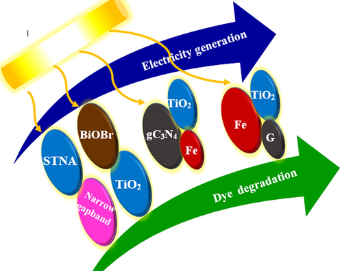
Effect of different anodic nanocomposite on electricity generation and dye degradation in PFC.
An example of using a composite photoanode in the PFC systems is the work of Liu et al (Liu et al., 2011). A short TiO2_nanotube_array (STNA)-based PFC system was constructed for electrical power generation from different refractory organic compounds and simultaneous wastewater treatment. The current-voltage_characteristics_of PFC systems using different photoanode materials (pure and composite) were compared under solar LR. It was shown that decorating the pure_STNA_electrode_material with narrow Eg semiconductors (e.g. Cu2O and CdS), under simulated solar LR, significantly increases Jsc and JVmax values. For the CdS/STNA photoanode, Jsc and JVmax were 1.66–1.75 and_1.38–2.41_times_higher than those of the respective pure STNA_photoanode for three different organic compounds solution. That means the PFC system can work outdoors_under_solar_irradiation and light a LED indicative lamp by using this composite photoanode material.
7 Photocatalytic fuel cell and Fenton process
As already mentioned, due to its significant advantages, PFC is an important technology for wastewater treatment and simultaneous power generation. Recently, much attention has been paid to the_development_of photoanode and photocathode to improve performance (Li et al., 2014; Bai et al., 2016; Chen et al., 2012; Zang et al., 2014; Wang et al., 2015). During this time, novel photoelectrodes were designed to increase LT absorption and the separation of the e− - h+ or surface area, which partially enhances the performance in the degradation of organic pollutants and simultaneous power generation. However, the efficiency is now restricted, as there are many challenges from the aspect of intrinsic semiconductor constraints. The most important constraints of PFCs are the radical reactions taking place on the photoanode and photocathode surfaces. However, the surface area cannot be significantly enlarged, which is a serious constraint on PFCs in the degradation of organic pollutants (Zhao et al., 2017). So how to increase the efficiency of radical reactions that only affects the surface of electrodes is the key to solving this problem. Lately, the Bio electro-Fenton system, which includes MFCs and the Fenton process, has_been_studied as a promising method for organic pollutant treatment (Zhang et al., 2015; Zhuang et al., 2010; Fu et al., 2010; Thor et al., 2020). This integration is an attempt to extend H2O2 production technologies that are cost-effective, efficient_and_sustainable for pollutant treatment (Zhang et al., 2015). The e− produced by a microbial reaction are applied by electro-Fenton reactions to treat pollutants in the MFC cathode. The reaction of ferrous ions with H2O2 produced by the process of oxygen reduction leads to •OH production (Feng et al., 2010). This process is identified as the_electro-Fenton_process (Brillas et al., 2009).
The PFC_system can generate its external voltage through the self-bias between photoanode_and_cathode, the process which is accompanied by degradation of organic pollutants. If ferrous ions are added, a self-bias Fenton-PFC system will be created to decompose organic pollutants and simultaneously produce power. Since PFC is more useful than other fuel cells for the oxidation process of organic_and_inorganic materials, it could be a more appropriate partner for the Fenton process, given the considerable challenges in developing and exploiting these systems. The system can minimize maintenance costs and since it uses a PEC system that employs photoexcitation to generate e− and h+ using n-type semiconductor as a photocatalyst, it does not require monitoring (Yang et al., 2014). The hybrid Fenton-PFC_system_has the following characteristics (Zhao et al., 2017):
-
It develops radical reactions from the_electrode_surface to the overall solution with the entry of the Fenton_reaction_in_the_system, which significantly increases the efficiency of radical reactions in the organic matter degradation and the electrical power generation relative to the traditional PFC.
-
It does not require external H2O2 as an oxidizing agent because HO , HO2 , and H2O2 can be generated on the electrodes under LR, which decreases operating costs.
-
It does not need external voltages and additional ferrous_ions_because the self-bias voltage yielded can transmit to the cathode and achieve conversion to Fe2+/Fe3+.
-
It extremely produces sludge because of the radical reaction by using low levels of ferrous ions.
The mechanism of pollutant removal in the hybrid Fenton-PFC_system is as follows (Nordin et al., 2017):
At PFC anode
At Fenton cathode
At Fenton anode
At PFC cathode
Overall Fenton process
It can be concluded that the hybrid Fenton-PFC system is a promising technology for organic pollutants removal and generating electricity simultaneously. In this hybrid system, PFC is employed to produce
to produce H2O2 electrons as Fenton's reagent. Fig. 5 illustrates the schematic of the hybrid Fenton-PFC system for pollutant removal. Generally, the unique features of the hybrid Fenton-PFC system result in a fast and stable catalytic system with excellent efficiency (Nordin et al., 2017).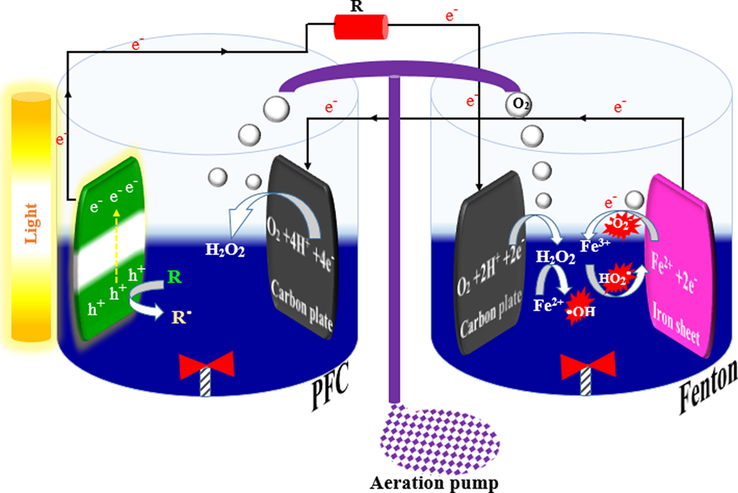
An example of the hybrid Fenton-PFC system.
8 Conclusions and recommendations
In this work, a review of the most representative research specific to PFCs for wastewater treatment and synchronous power generation has been performed. Since the performance of PFC is usually specified by the electrodes, most researches focus on the production of electrode materials in recent studies. Given that the features of functional electrode materials are significantly dependent on their structure, recent advances in nanotechnology produces efficient electrodes. In this regard, various nanomaterials were tested such as CdS–TiO2, CdS/ZnS/TiO2, Ag/AgCl/GO, Ag-TiO2, WO3/FTO, ZnO/BaTiO3, ZnO/Zn. These electrodes are based on nanomaterials can led to enhance efficiency of the degradation of organic contaminants, energy performance, or both. But among these nanomaterials, TiO2 is employed as the most efficient photodanode catalyst, due to its high oxidizing power, excellent stability low cost, low recombination rate (that can enhance efficiency in the utilization of the photogenerated e− to produce the Fenton’s reagent) and also because it is an n-type semiconductor. But, this application is still limited because TiO2 only responds to UV light, which makes up <5% of solar energy, and the recombinant high electron / hole pair reduces a large amount of energy lost due to heat, decreasing quantum efficiency and thus treatment performance. Thus, the use of effective methods to overcome TiO2 deficiency is essential to enhance the catalytic activity of the anode. Among the researches, TiO2 modification with a narrow band gap semiconductor shows excellent potential. Because such modifications can effectively enlarge the catalyst light response area due to the semiconductor excitation of the narrow band gap, especially in the visible light region. On the other hand, the heterogeneous performance between the two semiconductors separates the generated carriers from the photogenerated and increases the lifetime and improves the quantum performance of the composite catalyst.
However, a more in-depth analysis of the photoanode materials should be more performed. Due to insignificant conductivity characterizations and its photo absorbency in the range of the VLR up to approximately infrared, the photoanode materials with low Eg have led the negligible change of power density, photocurrent and voltage output in the attendance and inexistence of the LR source and pollutant degradation. Moreover, the degradation trend of pollutants is affected by the e− activity recombination rate and Eg of photoanode materials. In the PFCs, as it maintains the e− - h+ pair separation of photoanode, the presence of dissolved oxygen can improve the degradation of pollutants and power generation.
Durability and reusability of photonode is essential for its application in the real world and economic practicality. One method to determine the stability and reusability of electrodes is XRD test. In this regard, XRD test can be applied for fresh and used photoanodes and if the crystalline phase of the photoanode remains constant after several consecutive periods, it can be seen that the used photoanode can be reused and therefore can be used in the wastewater treatment.
Regarding dye removal by PFCs, it can be concluded that the molecular structure of the dyes and LR source significantly influence on dye degradation and power generation. Due to the formation of HO, higher aeration rate, electrolyte pH and degradability of pollutants, as well as a lower concentration of a pollutant in the PFCs, led to an increase of pollutant degradation. However, an increase in resistance leads to reduced pollutant degradation. Furthermore, as raising the LR intensity generates more photo-excited e−- h+ pairs, the efficiency is enhanced. The results of the analyzed studies show that PFCs with the membrane electrode assembly structure has a higher pollutant decomposition and simultaneous power generation. Meanwhile, the increase of organic pollutants in the wastewater led to enhance electricity generation.
In the hybrid PFC-Fenton system, as a result of the introduction of ferrous ions into the PFC to strengthen the radicals' reaction and promote •OH production, the performance of the system was improved for both degradations of pollutant and power production. The use of photoanode and photocathode materials in different forms can lead to an outstanding improvement of both pollutant decomposition and power generation.
Nowadays, the utilization of PFC systems was mostly concentrated on the expansion of high-efficiency photoanode substances, binary photoelectrodes PFCs, and multi-purpose PFCs. Further research work is necessary to improve the performance and economic viability of these systems, the main aspects for each answer are still pending focusing on: i) what is the relevance between the physicochemical characteristics of electrode materials and the performance of related cell?; ii) how can state-of-the-art nanotechnology be combined to further increase the cell yield?; iii) can a PFC device be applied for practical usage?; and iv) how to efficiently employ the generated electricity or H2? Therefore, these topics are of critical significance for future expansions of any PFC device. Merged approaches that combine advances in theoretical computation and experimental data can supply the needed insights towards the essential related between electrode materials and cell efficiency. This can sufficiently progress the basic knowledge of electrode structures and result in a new strategy of energy generation with practical and efficient real-life use.
Declaration of Competing Interest
The authors declare that they have no known competing financial interests or personal relationships that could have appeared to influence the work reported in this paper.
References
- The effect and mechanism of organic pollutants oxidation and chemical energy conversion for neutral wastewater via strengthening reactive oxygen species. Sci. Total Environ.. 2019;651:1226-1235.
- [Google Scholar]
- Electroactive modified carbon nanotube filter for simultaneous detoxification and sequestration of Sb (III) Environ. Sci. Technol.. 2019;53:1527-1535.
- [Google Scholar]
- An effective self-driven PFC-PEC hybrid system for hydrogen generation from organic substance. Electrochim. Acta. 2017;245:379-385.
- [Google Scholar]
- Advanced oxidation processes based on zero-valent aluminium for treating textile wastewater. Chem. Eng. J.. 2018;348:67-73.
- [Google Scholar]
- Modeling and optimization of acid blue 193 removal by UV and peroxydisulfate process. J. Environ. Eng.. 2018;144:06018003.
- [Google Scholar]
- Pesticide decontamination using UV/ferrous-activated persulfate with the aid neuro-fuzzy modeling: a case study of Malathion. Food Res. Int.. 2020;137:109557
- [Google Scholar]
- A facile two-step fabrication of titanium dioxide coated copper oxide nanowires with enhanced photocatalytic performance. Mater. Charact.. 2020;159:110042
- [Google Scholar]
- Construction of novel Z-scheme nitrogen-doped carbon dots/{0 0 1} TiO2 nanosheet photocatalysts for broad-spectrum-driven diclofenac degradation: Mechanism insight, products and effects of natural water matrices. Chem. Eng. J.. 2019;356:857-868.
- [Google Scholar]
- Reactive species distribution characteristics and toluene destruction in the three-electrode DBD reactor energized by different pulsed modes. Chem. Eng. J. 2018
- [Google Scholar]
- Facile preparation and catalytic performance characterization of AuNPs-loaded hierarchical electrospun composite fibers by solvent vapor annealing treatment. Colloids Surf., A. 2019;561:283-291.
- [Google Scholar]
- Recent advances on photocatalytic fuel cell for environmental applications—the marriage of photocatalysis and fuel cells. Sci. Total Environ.. 2019;668:966-978.
- [Google Scholar]
- Carbon-based microbial-fuel-cell electrodes: from conductive supports to active catalysts. Adv. Mater.. 2017;29:1602547.
- [Google Scholar]
- Exploring the relationship between molecular structure of dyes and light sources for photodegradation and electricity generation in photocatalytic fuel cell. Chemosphere. 2018;209:935-943.
- [Google Scholar]
- Elucidating the effects of different photoanode materials on electricity generation and dye degradation in a sustainable hybrid system of photocatalytic fuel cell and peroxi-coagulation process. Chemosphere. 2019;214:614-622.
- [Google Scholar]
- Role of dissolved oxygen on the degradation mechanism of Reactive Green 19 and electricity generation in photocatalytic fuel cell. Chemosphere. 2018;194:675-681.
- [Google Scholar]
- A synergistic heterostructured ZnO/BaTiO3 loaded carbon photoanode in photocatalytic fuel cell for degradation of Reactive Red 120 and electricity generation. Chemosphere. 2019;219:277-285.
- [Google Scholar]
- Optimization of degradation of Reactive Black 5 (RB5) and electricity generation in solar photocatalytic fuel cell system. Chemosphere. 2017;184:112-119.
- [Google Scholar]
- Comparative study of persulfate oxidants promoted photocatalytic fuel cell performance: simultaneous dye removal and electricity generation. Chemosphere. 2019;234:658-667.
- [Google Scholar]
- Peroxymonosulfate enhanced antibiotic removal and synchronous electricity generation in a photocatalytic fuel cell. Electrochim. Acta. 2019;298:59-69.
- [Google Scholar]
- Efficient wastewater treatment and simultaneously electricity production using a photocatalytic fuel cell based on the radical chain reactions initiated by dual photoelectrodes. J. Hazard. Mater.. 2017;337:47-54.
- [Google Scholar]
- Simultaneous pollutant degradation and power generation in visible-light responsive photocatalytic fuel cell with an Ag-TiO2 loaded photoanode. Nano-Struct. Nano-Objects. 2018;15:167-172.
- [Google Scholar]
- Significant tetracycline hydrochloride degradation and electricity generation in a visible-light-driven dual photoelectrode photocatalytic fuel cell using BiVO4/TiO2 NT photoanode and Cu2O/TiO2 NT photocathode. Electrochim. Acta. 2019;320:134617
- [Google Scholar]
- Photoelectrochemical cell for simultaneous electricity generation and heavy metals recovery from wastewater. J. Hazard. Mater.. 2017;323:681-689.
- [Google Scholar]
- A micro photocatalytic fuel cell with an air-breathing, membraneless and monolithic design. Sci. Bull.. 2016;61:1699-1710.
- [Google Scholar]
- Effect of the nature of cadmium salts on the effectiveness of CdS SILAR deposition and its consequences on the performance of sensitized solar cells. J. Phys. Chem. C. 2014;118:22873-22880.
- [Google Scholar]
- A microbial fuel cell-coupled constructed wetland promotes degradation of azo dye decolorization products. Ecol. Eng.. 2016;94:455-463.
- [Google Scholar]
- Studies on an ultrasonic atomization feed direct methanol fuel cell. Ultrason. Sonochem.. 2017;34:60-66.
- [Google Scholar]
- Evaluation of cathode contamination with Ca2+ in proton exchange membrane fuel cells. Electrochim. Acta. 2018;259:510-516.
- [Google Scholar]
- Cross-linked anion exchange membranes with pendent quaternary pyrrolidonium salts for alkaline polymer electrolyte membrane fuel cells. J. Power Sources. 2015;295:259-267.
- [Google Scholar]
- Evaluation of photocatalytic fuel cell (PFC) for electricity production and simultaneous degradation of methyl green in synthetic and real greywater effluents. J. Environ. Manage.. 2018;228:383-392.
- [Google Scholar]
- Recent advances in nanomaterials for water protection and monitoring. Chem. Soc. Rev.. 2017;46:6946-7020.
- [Google Scholar]
- Efficient visible driven photocatalyst, silver phosphate: performance, understanding and perspective. Chem. Soc. Rev.. 2015;44:7808-7828.
- [Google Scholar]
- Optimization and application of TiO2/Ti–Pt photo fuel cell (PFC) to effectively generate electricity and degrade organic pollutants simultaneously. Water Res.. 2014;62:1-10.
- [Google Scholar]
- Modeling and optimization of photocatalytic/photoassisted-electro-Fenton like degradation of phenol using a neural network coupled with genetic algorithm. J. Ind. Eng. Chem.. 2014;20:1852-1860.
- [Google Scholar]
- Study of the photocurrent in a photocatalytic fuel cell for wastewater treatment and the effects of TiO2 surface morphology to the apportionment of the photocurrent. Electrochim. Acta. 2016;192:319-327.
- [Google Scholar]
- Photocatalysis and photoelectrocatalysis using (CdS-ZnS)/TiO2 combined photocatalysts. Appl. Catal. B. 2011;107:188-196.
- [Google Scholar]
- Energy-efficient degradation of rhodamine B in a LED illuminated photocatalytic fuel cell with anodic Ag/AgCl/GO and cathodic ZnIn 2 S 4 catalysts. RSC Adv.. 2016;6:12068-12075.
- [Google Scholar]
- Degradation of refractory organic compounds by photocatalytic fuel cell with solar responsive WO3/FTO photoanode and air-breathing cathode. J. Colloid Interface Sci.. 2017;500:220-227.
- [Google Scholar]
- A highly efficient immobilized ZnO/Zn photoanode for degradation of azo dye Reactive Green 19 in a photocatalytic fuel cell. Chemosphere. 2017;166:118-125.
- [Google Scholar]
- A solar responsive photocatalytic fuel cell with a heterostructured ZnFe2O4/TiO2-NTs photoanode and an air-breathing cathode. Int. J. Hydrogen Energy. 2017;42:29201-29209.
- [Google Scholar]
- Highly-stable and efficient photocatalytic fuel cell based on an epitaxial TiO 2/WO 3/W nanothorn photoanode and enhanced radical reactions for simultaneous electricity production and wastewater treatment. Appl. Energy. 2018;220:127-137.
- [Google Scholar]
- Significant enhancement of micropollutant photocatalytic degradation using a TiO2 nanotube array photoanode based photocatalytic fuel cell. Chem. Eng. J.. 2018;354:553-562.
- [Google Scholar]
- Influence of Mn-doping on the photocatalytic and solar cell efficiency of CuO nanowires. Inorg. Chem. Commun.. 2017;76:71-76.
- [Google Scholar]
- Controllable synthesis of Zn x Cd1–x S@ ZnO core-shell nanorods with enhanced photocatalytic activity. Langmuir. 2012;28:10558-10564.
- [Google Scholar]
- Preparation and photocatalytic properties of visible light driven Ag-AgBr-RGO composite. Sep. Purif. Technol.. 2018;190:278-287.
- [Google Scholar]
- Oxygen vacancies induced visible-light photocatalytic activities of CaCu3Ti4O12 with controllable morphologies for antibiotic degradation. Appl. Catal. B. 2018;221:422-432.
- [Google Scholar]
- Degradation of amoxicillin by persulfate activated with Fe3O4/GO nanocomposite in aqueous solution. Desalin. Water Treat.. 2019;153:392-401.
- [Google Scholar]
- Combination of nanophotocatalysis with electro-Fenton-like process in the removal of phenol from aqueous solution: GC analysis and response surface approach. Int. J. Indus. Chem.. 2012;3:27.
- [Google Scholar]
- An innovative combination of electrochemical and photocatalytic processes for decontamination of bisphenol A endocrine disruptor form aquatic phase: Insight into mechanism, enhancers and bio-toxicity assay. Sep. Purif. Technol.. 2019;220:42-51.
- [Google Scholar]
- Heterogeneous photocatalysis of a dye solution using supported TiO2 nanoparticles combined with homogeneous photoelectrochemical process: molecular degradation products. J. Mol. Catal. A: Chem.. 2011;338:84-91.
- [Google Scholar]
- Photocatalytic degradation of bisphenol A by Ag3PO4 under visible light. Catal. Commun.. 2013;34:30-34.
- [Google Scholar]
- Aerated visible-light responsive photocatalytic fuel cell for wastewater treatment with producing sustainable electricity in neutral solution. Chem. Eng. J.. 2014;252:89-94.
- [Google Scholar]
- Tang, T., Li, K., Ying, D., Sun, T., Wang, Y., Jia, J., 2014. High efficient aqueous-film rotating disk photocatalytic fuel cell (RDPFC) with triple functions: cogeneration of hydrogen and electricity with dye degradation, international journal of hydrogen energy 39 (2014) 10258–10266.
- A solar-driven photocatalytic fuel cell with dual photoelectrode for simultaneous wastewater treatment and hydrogen production. J. Mater. Chem. A. 2015;3:3416-3424.
- [Google Scholar]
- Degrading organic pollutants and generating electricity in a dual-chamber rotating-disk photocatalytic fuel cell (RPFC) with a TiO2 nanotube array anode. Res. Chem. Intermed.. 2015;41:5365-5377.
- [Google Scholar]
- A solar light driven dual photoelectrode photocatalytic fuel cell (PFC) for simultaneous wastewater treatment and electricity generation. J. Hazard. Mater.. 2016;311:51-62.
- [Google Scholar]
- Enhanced electricity generation and degradation of the azo dye Reactive Green 19 in a photocatalytic fuel cell using ZnO/Zn as the photoanode. J. Cleaner Prod.. 2016;127:579-584.
- [Google Scholar]
- Methods to improve electrochemical treatment effect of dye wastewater. J. Hazard. Mater.. 2006;131:90-97.
- [Google Scholar]
- TiO2-mediated photocatalytic degradation of a triphenylmethane dye (gentian violet), in aqueous suspensions. Dyes Pigm.. 2003;56:37-49.
- [Google Scholar]
- Photocatalytic degradation of two selected textile dye derivatives, eosine yellowish and p-rosaniline, in aqueous suspensions of titanium dioxide. J. Environ. Sci. Health, Part A. 2003;38:2581-2598.
- [Google Scholar]
- A biocathode-driven photocatalytic fuel cell using an Ag-doped TiO2/Ti mesh photoanode for electricity generation and pollutant degradation. J. Photochem. Photobiol., A. 2017;348:238-245.
- [Google Scholar]
- Enhanced organic pollutants degradation and electricity production simultaneously via strengthening the radicals reaction in a novel Fenton-photocatalytic fuel cell system. Water Res.. 2017;108:293-300.
- [Google Scholar]
- Improved dye removal and simultaneous electricity production in a photocatalytic fuel cell coupling with persulfate activation. Electrochim. Acta. 2018;270:330-338.
- [Google Scholar]
- A Visible light responsive photocatalytic fuel cell using BiOBr/TiO2 nanotube array photoanode for simultaneous wastewater treatment and electricity generation. Chem. Lett.. 2018;47:613-616.
- [Google Scholar]
- Oxidative removal of bisphenol A by UV-C/peroxymonosulfate (PMS): kinetics, influence of co-existing chemicals and degradation pathway. Chem. Eng. J.. 2015;276:193-204.
- [Google Scholar]
- Selective transformation of β-lactam antibiotics by peroxymonosulfate: reaction kinetics and nonradical mechanism. Environ. Sci. Technol.. 2018;52:1461-1470.
- [Google Scholar]
- Oxidation of organic compounds in water by unactivated peroxymonosulfate. Environ. Sci. Technol.. 2018;52:5911-5919.
- [Google Scholar]
- Solar light responsive poly (vinyl alcohol)-assisted hydrothermal synthesis of immobilized TiO2/Ti film with the addition of peroxymonosulfate for photocatalytic degradation of ciprofloxacin in aqueous media: a mechanistic approach. J. Phys. Chem. C. 2017;122:406-421.
- [Google Scholar]
- Visible-light responsive photocatalytic fuel cell based on WO3/W photoanode and Cu2O/Cu photocathode for simultaneous wastewater treatment and electricity generation. Environ. Sci. Technol.. 2012;46:11451-11458.
- [Google Scholar]
- Optofluidics based micro-photocatalytic fuel cell for efficient wastewater treatment and electricity generation. Lab Chip. 2014;14:3368-3375.
- [Google Scholar]
- Influence of supporting electrolyte in electricity generation and degradation of organic pollutants in photocatalytic fuel cell. Environ. Sci. Pollut. Res.. 2016;23:16716-16721.
- [Google Scholar]
- In-situ utilization of generated electricity in a photocatalytic fuel cell to enhance pollutant degradation. J. Photochem. Photobiol., A. 2017;343:51-57.
- [Google Scholar]
- Evaluate the performance of Fenton process for the removal of Methylene Blue from aqueous solution: experimental, neural network modeling and optimization. Environ. Prog. Sustainable Energy. 2020;39(2):1-7.
- [Google Scholar]
- Significant photocatalytic degradation and electricity generation in the photocatalytic fuel cell (PFC) using novel anodic nanocomposite of Fe, graphene oxide, and titanium phosphate. Electrochim. Acta. 2018;271:41-48.
- [Google Scholar]
- Visible-light photocatalytic fuel cell with Z-scheme g-C3N4/Fe0/TiO2 anode and WO3 cathode efficiently degrades berberine chloride and stably generates electricity. Sep. Purif. Technol.. 2019;212:774-782.
- [Google Scholar]
- A study on tandem photoanode and photocathode for photocatalytic formaldehyde fuel cell. Electrochim. Acta. 2020;136476
- [Google Scholar]
- Novel application of a Z-scheme photocatalyst of Ag3PO4@ g-C3N4 for photocatalytic fuel cells. J. Environ. Manage.. 2020;254:109738
- [Google Scholar]
- Greywater and bacteria removal with synchronized energy production in photocatalytic fuel cell based on anodic TiO2/ZnO/Zn and cathodic CuO/Cu. Chemosphere. 2020;245:125565
- [Google Scholar]
- Influence of pH and DO on the ofloxacin degradation in water by UVA-LED/TiO2 nanotube arrays photocatalytic fuel cell: mechanism, ROSs contribution and power generation. J. Hazard. Mater.. 2020;383:121220
- [Google Scholar]
- A Z-scheme WO3 loaded-hexagonal rod-like ZnO/Zn photocatalytic fuel cell for chemical energy recuperation from food wastewater treatment. Appl. Surf. Sci.. 2020;145945
- [Google Scholar]
- Explicating charge transfer dynamics in anodic TiO2/ZnO/Zn photocatalytic fuel cell for ameliorated palm oil mill effluent treatment and synchronized energy generation. J. Photochem. Photobiol., A. 2020;391:112353
- [Google Scholar]
- Photocatalytic removal organic matter and bacteria simultaneously from real WWTP effluent with power generation concomitantly: using an ErAlZnO photo-anode. Sep. Purif. Technol.. 2018;191:101-107.
- [Google Scholar]
- Photocatalytic inactivation of bacteria by photocatalyst Bi2WO6 under visible light. Catal. Commun.. 2009;10:1940-1943.
- [Google Scholar]
- Photoelectrochemical sterilization of microbial cells by semiconductor powders. FEMS Microbiol. Lett.. 1985;29:211-214.
- [Google Scholar]
- Efficient visible-light-induced photocatalytic disinfection on sulfur-doped nanocrystalline titania. Environ. Sci. Technol.. 2005;39:1175-1179.
- [Google Scholar]
- Apatite-coated Ag/AgBr/TiO2 visible-light photocatalyst for destruction of bacteria. J. Am. Chem. Soc.. 2007;129:9552-9553.
- [Google Scholar]
- Sulfur doped carbon quantum dots loaded hollow tubular g-C3N4 as novel photocatalyst for destruction of Escherichia coli and tetracycline degradation under visible light. Chem. Eng. J.. 2019;378:122132
- [Google Scholar]
- Fabrication of novel g-C3N4 based MoS2 and Bi2O3 nanorods embedded ternary nanocomposites for superior photocatalytic performance and destruction of bacteria. New J. Chem. 2020
- [Google Scholar]
- Review of recent trends in photoelectrocatalytic conversion of solar energy to electricity and hydrogen. Appl. Catal. B. 2017;210:235-254.
- [Google Scholar]
- Photoactivated Fuel Cells (PhotoFuelCells). An alternative source of renewable energy with environmental benefits. AIMS Mater. Sci.. 2016;3:270-288.
- [Google Scholar]
- A highly efficient BiVO4/WO3/W heterojunction photoanode for visible-light responsive dual photoelectrode photocatalytic fuel cell. Appl. Catal. B. 2016;183:224-230.
- [Google Scholar]
- Production of electricity and hydrogen by photocatalytic degradation of organic wastes in a photoelectrochemical cell: the concept of the photofuelcell: a review of a re-emerging research field. J. Hazard. Mater.. 2011;185:575-590.
- [Google Scholar]
- Appropriate strategies for determining the photoconversion efficiency of water photoelectrolysis cells: a review with examples using titania nanotube array photoanodes. Sol. Energy Mater. Sol. Cells. 2008;92:374-384.
- [Google Scholar]
- Quantum dot sensitized titania applicable as photoanode in photoactivated fuel cells. The Journal of Physical Chemistry C. 2012;116:16901-16909.
- [Google Scholar]
- B. O'regan, M. Grätzel, A low-cost, high-efficiency solar cell based on dye-sensitized colloidal TiO2 films, nature 353 (1991) 737.
- Efficient electricity production and simultaneously wastewater treatment via a high-performance photocatalytic fuel cell. Water Res.. 2011;45:3991-3998.
- [Google Scholar]
- Photocatalytic fuel cell (PFC) and dye self-photosensitization photocatalytic fuel cell (DSPFC) with BiOCl/Ti photoanode under UV and visible light irradiation. Environ. Sci. Technol.. 2013;47:3490-3497.
- [Google Scholar]
- Performance characteristics of a membraneless solar responsive photocatalytic fuel cell with an air-breathing cathode under different fuels and electrolytes and air conditions. Electrochim. Acta. 2015;182:280-288.
- [Google Scholar]
- Degradation of Rhodamine B using a visible-light driven photocatalytic fuel cell. Electrochim. Acta. 2014;144:7-15.
- [Google Scholar]
- Evaluation of UV/H2O2 advanced oxidation process (AOP) for the degradation of diazo dye Reactive Green 19 in aqueous solution. Desalin. Water Treat.. 2014;52:1571-1577.
- [Google Scholar]
- Highly efficient and visible light responsive heterojunction composites as dual photoelectrodes for photocatalytic fuel cell. Catalysts. 2018;8:30.
- [Google Scholar]
- All-solid-state Z-scheme in CdS–Au–TiO 2 three-component nanojunction system. Nat. Mater.. 2006;5:782.
- [Google Scholar]
- Z-scheme water splitting using two different semiconductor photocatalysts. ACS Catal.. 2013;3:1486-1503.
- [Google Scholar]
- Electrochemical photolysis of water at a semiconductor electrode. Nature. 1972;238:37.
- [Google Scholar]
- TiO2 nanoparticles with superior hydrogen evolution and pollutant degradation performance. Int. J. Hydrogen Energy. 2019;44:24162-24173.
- [Google Scholar]
- IJHE mobilizes to reach hydrogen civilization. Int. J. Hydrogen Energy. 2008;1:1-2.
- [Google Scholar]
- M.A. Ruiz-Gómez, T.-M. Leticia M., F.-T. Mayra Z., M. Edgar, J.-R. Isaías, Hydrogen evolution from pure water over a new advanced photocatalyst Sm2GaTaO7, international journal of hydrogen energy 38 (2013) 12554-12561.
- Kelly, N.A., G. Thomas L., Solar energy concentrating reactors for hydrogen production by photoelectrochemical water splitting, International Journal of Hydrogen Energy 33 (2008) 6420–6431.
- Photocatalysis for renewable energy production using PhotoFuelCells. Molecules. 2014;19:19732-19750.
- [Google Scholar]
- Photoelectrocatalytic production of hydrogen peroxide using a photo (catalytic) fuel cell. J. Photochem. Photobiol., A. 2020;389:112210
- [Google Scholar]
- Hydrogen production by photocatalytic steam reforming of methanol on noble metal-modified TiO2. J. Catal.. 2010;273:182-190.
- [Google Scholar]
- Kinetic and mechanistic study of the photocatalytic reforming of methanol over Pt/TiO2 catalyst. Appl. Catal. B. 2014;146:249-257.
- [Google Scholar]
- Photoelectrochemical cells for solar hydrogen production: current state of promising photoelectrodes, methods to improve their properties, and outlook. Energy Environ. Sci.. 2013;6:347-370.
- [Google Scholar]
- Overall photoelectrochemical water splitting using tandem cell under simulated sunlight. ChemSusChem. 2016;9:61-66.
- [Google Scholar]
- Khan, S.U., Mofareh, A.-S., Ingler, W.B., 2002. Efficient photochemical water splitting by a chemically modified n-TiO2, Science 297 (2002) 2243–2245.
- Photoelectrocatalytic activity of a hydrothermally grown branched Zno nanorod-array electrode for paracetamol degradation. J. Hazard. Mater.. 2015;291:9-17.
- [Google Scholar]
- p–n Heterojunction photoelectrodes composed of Cu2O-loaded TiO2 nanotube arrays with enhanced photoelectrochemical and photoelectrocatalytic activities. Energy Environ. Sci.. 2013;6:1211-1220.
- [Google Scholar]
- Synthesis of Cu2O nanocrystals from cubic to rhombic dodecahedral structures and their comparative photocatalytic activity. J. Am. Chem. Soc.. 2011;134:1261-1267.
- [Google Scholar]
- An investigation of interfacial and photoelectrochemical performance of thermally prepared C, N-codoped TiO2 photoanodes for water splitting. ChemistrySelect. 2017;2:288-294.
- [Google Scholar]
- New insight into understand the enhanced photoconductivity properties of Ti (O2) plate spurted with Al2O3 for water oxidation. ChemistrySelect. 2016;1:5037-5041.
- [Google Scholar]
- A review of ZnO nanoparticles as solar photocatalysts: synthesis, mechanisms and applications. Renew. Sustain. Energy Rev.. 2018;81:536-551.
- [Google Scholar]
- Visible-light photocatalytic hydrogen production from ethanol–water mixtures using a Pt–CdS–TiO2 photocatalyst. Catal. Today. 2010;151:53-57.
- [Google Scholar]
- Photoelectrocatalytic hydrogen production by water splitting using BiVO4 photoanodes. Chem. Eng. J.. 2016;286:91-97.
- [Google Scholar]
- Towards highly efficient photoanodes: boosting sunlight-driven semiconductor nanomaterials for water oxidation. Nanoscale. 2014;6:7142-7164.
- [Google Scholar]
- Recent advances in visible-light-responsive photocatalysts for hydrogen production and solar energy conversion–from semiconducting TiO 2 to MOF/PCP photocatalysts. PCCP. 2013;15:13243-13253.
- [Google Scholar]
- Recent theoretical progress in the development of photoanode materials for solar water splitting photoelectrochemical cells. J. Mater. Chem. A. 2015;3:10632-10659.
- [Google Scholar]
- Photocatalyzed degradation of acid orange 7 dye under sunlight and ultraviolet irradiation using Ni-doped ZnO nanoparticles. Desalin. Water Treat.. 2019;165:321-332.
- [Google Scholar]
- Photoelectrocatalytic hydrogen production using nanoparticulate titania and a novel Pt/Carbon electrocatalyst: the concept of the “Photoelectrocatalytic Leaf”. Appl. Surf. Sci.. 2015;333:147-151.
- [Google Scholar]
- Organohalide lead perovskites for photovoltaic applications. Energy Environ. Sci.. 2014;7:2448-2463.
- [Google Scholar]
- Metal oxide photoanodes for solar hydrogen production. J. Mater. Chem.. 2008;18:2298-2303.
- [Google Scholar]
- Photoelectrochemical reaction of biomass and bio-related compounds with nanoporous TiO2 film photoanode and O2-reducing cathode. Electrochem. Commun.. 2006;8:336-340.
- [Google Scholar]
- Electrical power and hydrogen production from a photo-fuel cell using formic acid and other single-carbon organics. J. Mater. Chem.. 2012;22:10709-10715.
- [Google Scholar]
- Production of electricity by photoelectrochemical oxidation of ethanol in a PhotoFuelCell. Appl. Catal. B. 2010;99:307-313.
- [Google Scholar]
- Photoelectrocatalytic degradation of refractory organic compounds enhanced by a photocatalytic fuel cell. Appl. Catal. B. 2012;111:485-491.
- [Google Scholar]
- A TiO2-nanotube-array-based photocatalytic fuel cell using refractory organic compounds as substrates for electricity generation. Chem. Commun.. 2011;47:10314-10316.
- [Google Scholar]
- Converting hazardous organics into clean energy using a solar responsive dual photoelectrode photocatalytic fuel cell. J. Hazard. Mater.. 2013;262:304-310.
- [Google Scholar]
- Semiconductor heterojunction photocatalysts: design, construction, and photocatalytic performances. Chem. Soc. Rev.. 2014;43:5234-5244.
- [Google Scholar]
- TiO2 photocatalysis: a historical overview and future prospects. Jpn. J. Appl. Phys.. 2005;44:8269.
- [Google Scholar]
- TiO2 nanotube arrays of 1000 μm length by anodization of titanium foil: phenol red diffusion. J. Phys. Chem. C. 2007;111:14992-14997.
- [Google Scholar]
- Niobium doping effects on TiO2 mesoscopic electron transport layer-based perovskite solar cells. ChemSusChem. 2015;8:2392-2398.
- [Google Scholar]
- Pt nanoparticles supported on highly dispersed TiO2 coated on SBA-15 as an efficient and recyclable catalyst for liquid-phase hydrogenation. J. Catal.. 2013;300:9-19.
- [Google Scholar]
- TiO2 Nanotube arrays modified with Cr-doped SrTiO3 nanocubes for highly efficient hydrogen evolution under visible light, chemistry–A. Eur. J.. 2014;20:2654-2662.
- [Google Scholar]
- A critical review on the recent progress of synthesizing techniques and fabrication of TiO2-based nanotubes photocatalysts. Appl. Catal. A. 2014;481:127-142.
- [Google Scholar]
- Artificial photochemical nitrogen cycle to produce nitrogen and hydrogen from ammonia by platinized TiO 2 and its application to a photofuel cell. Chem. Commun.. 2005;12:1625-1627.
- [Google Scholar]
- Aldol condensation products during photocatalytic oxidation of ethanol in a photoelectrochemical cell. Appl. Catal. B. 2010;100:124-132.
- [Google Scholar]
- An efficient photoelectrochemical cell functioning in the presence of organic wastes. Sol. Energy Mater. Sol. Cells. 2010;94:592-597.
- [Google Scholar]
- Synthesis and enhancement of visible light activities of nitrogen-doped BaTiO3. J. Alloy. Compd.. 2014;615:243-248.
- [Google Scholar]
- Ag loaded flower-like BaTiO 3 nanotube arrays: Fabrication and enhanced photocatalytic property. CrystEngComm. 2012;14:1473-1478.
- [Google Scholar]
- Effect of ferroelectricity on solar-light-driven photocatalytic activity of BaTiO3 – influence on the carrier separation and stern layer formation. Chem. Mater.. 2013;25:4215-4223.
- [Google Scholar]
- Enhanced photocatalytic activity for the degradation of rhodamine B by integrating salinity gradient power into a photocatalytic fuel cell. RSC Adv.. 2015;5:94184-94190.
- [Google Scholar]
- A solar responsive photocatalytic fuel cell with the membrane electrode assembly design for simultaneous wastewater treatment and electricity generation. J. Hazard. Mater.. 2018;358:346-354.
- [Google Scholar]
- Photoelectrochemical water splitting over ordered honeycomb hematite electrodes stabilized by alumina shielding. Energy Environ. Sci.. 2012;5:6375-6382.
- [Google Scholar]
- Solar photocatalytic fuel cell using CdS–TiO2 photoanode and air-breathing cathode for wastewater treatment and simultaneous electricity production. Chem. Eng. J.. 2014;253:174-182.
- [Google Scholar]
- UV light-activated decomposition/cleaning of concentrated biomass wastes involving also solid suspensions with remarkably high quantum efficiency. Appl. Catal. B. 2009;91:254-261.
- [Google Scholar]
- Highly active oxide photocathode for photoelectrochemical water reduction. Nat. Mater.. 2011;10:456.
- [Google Scholar]
- S. Masudy-Panah, R. Siavash Moakhar, C.S. Chua, A. Kushwaha, G.K. Dalapati, Stable and efficient CuO based photocathode through oxygen-rich composition and Au–Pd nanostructure incorporation for solar-hydrogen production, ACS Appl Mater Interfaces 9 (2017) 27596–27606.
- S. Masudy-Panah, R. Siavash Moakhar, C.S. Chua, H.R. Tan, T.I. Wong, D. Chi, G.K. Dalapati, Nanocrystal engineering of sputter-grown CuO photocathode for visible-light-driven electrochemical water splitting, ACS Appl. Mater. Interf. 8 (2016) 1206–1213.
- Methods of photoelectrode characterization with high spatial and temporal resolution. Energy Environ. Sci.. 2015;8:2863-2885.
- [Google Scholar]
- Evaluation of synergy and bacterial regrowth in photocatalytic ozonation disinfection of municipal wastewater. Sci. Total Environ.. 2017;601:626-635.
- [Google Scholar]
- Self-assembling TiO2 nanorods on large graphene oxide sheets at a two-phase interface and their anti-recombination in photocatalytic applications. Adv. Funct. Mater.. 2010;20:4175-4181.
- [Google Scholar]
- ZnO and cobalt phthalocyanine hybridized graphene: efficient photocatalysts for degradation of rhodamine B. J. Colloid Interface Sci.. 2014;430:257-264.
- [Google Scholar]
- Sunlight-driven sustainable production of hydrogen peroxide using a CdS–graphene hybrid photocatalyst. J. Catal.. 2017;345:78-86.
- [Google Scholar]
- Photochemical fabrication of SnO2 dense layers on reduced graphene oxide sheets for application in photocatalytic degradation of p-nitrophenol. Appl. Catal. B. 2017;215:8-17.
- [Google Scholar]
- A bio-photoelectrochemical cell with a MoS 3-modified silicon nanowire photocathode for hydrogen and electricity production. Energy Environ. Sci.. 2014;7:3033-3039.
- [Google Scholar]
- Dye-sensitized photoelectrochemical cell on plasmonic Ag/AgCl@ chiral TiO2 nanofibers for treatment of urban wastewater effluents, with simultaneous production of hydrogen and electricity. Appl. Catal. B. 2015;168:25-32.
- [Google Scholar]
- Alternate switching between microbial fuel cell and microbial electrolysis cell operation as a new method to control H2O2 level in Bioelectro-Fenton system. J. Power Sources. 2015;291:108-116.
- [Google Scholar]
- A novel bioelectro-Fenton system for coupling anodic COD removal with cathodic dye degradation. Chem. Eng. J.. 2010;163:160-163.
- [Google Scholar]
- Degradation of azo dyes using in-situ Fenton reaction incorporated into H2O2-producing microbial fuel cell. Chem. Eng. J.. 2010;160:164-169.
- [Google Scholar]
- Explicating the importance of aeration and pH for Amaranth degradation and electricity generation in a viable hybrid system of photocatalytic fuel cell and electro-Fenton process. Sep. Purif. Technol.. 2020;239:116535
- [Google Scholar]
- A dual-chamber microbial fuel cell with conductive film-modified anode and cathode and its application for the neutral electro-Fenton process. Electrochim. Acta. 2010;55:2048-2054.
- [Google Scholar]
- Electro-Fenton process and related electrochemical technologies based on Fenton’s reaction chemistry. Chem. Rev.. 2009;109:6570-6631.
- [Google Scholar]
- Hybrid system of photocatalytic fuel cell and Fenton process for electricity generation and degradation of Reactive Black 5. Sep. Purif. Technol.. 2017;177:135-141.
- [Google Scholar]


