

Translate this page into:
Preparation and evaluation of high-transparent scratch-resistant thin films on plasma treated polycarbonate substrate
⁎Corresponding authors. Eshaghi@mut-es.ac.ir (Akbar Eshaghi) eshaghi.akbar@gmail.com (Akbar Eshaghi)
-
Received: ,
Accepted: ,
This article was originally published by Elsevier and was migrated to Scientific Scholar after the change of Publisher.
Peer review under responsibility of King Saud University.
Abstract
New simple aqueous sol–gel procedure has been used for producing hard transparent organic–inorganic coatings on polycarbonate (PC). Sol-gel thins films were prepared by mixing Si and Al aqueous alkoxides and applied on the plasma treated PC. Tetraethyl orthosilicate (TEOS), 3-glycidoxypropyltrimethoxysilane (GPTMS) and aluminum tri sec-butoxide were used as main precursors. Before applying coatings PC were treated by Dielectric Barrier Discharge (DBD) system being conducted at atmosphere pressure. The effects of temperature, sols volume ratios and aging time on the coatings properties were scrutinized. Chemical, structural, morphological, optical and mechanical analyses of the samples were done by ATR-FTIR, EDS, XRD, FE-SEM, TEM, UV/vis spectroscopy, ellipsometry, pencil hardness and eraser scratch methods. TEM results showed well-dispersed nano-particles in the liquid sol. All of the films showed higher average transmittance (89 %) than the raw PC (86 %) that was stemmed from the lower refractive index (1.481) than raw PC (1.58). Films indicated good adhesion onto the plasma treated substrates (5B). The pencil hardness of the PC substrate (4B) improved to 3H (8 pencil grade increment) with just a single layer coating (775 nm thickness) due to the preparation of new hard structures of interlocked Si and Al atoms.
Keywords
PC
Nanohybrid coatings
Sol-gel
Scratch resistance
Transmittance

1 Introduction
Polycarbonate (PC) is one of the most versatile materials being attractive in the recent years. This material contains unique properties such as high optical transmittance, low density, high fracture toughness, low production cost and high productivity. It has become the felicitous replacement for inorganic heavy glass materials in various applications such as solar cells (Hackmann, 2004; Jung, 2009), display panels, contact lenses, hard disks, smart windows and in the automotive industry (Schmauder, 2006). Despite all of its useful properties, PC always suffers from poor scratch resistance and vulnerability to the environmental damages. There are many efforts being done to increase its hardness and scratch resistance by applying sol–gel hard coatings (Le Bail, 2015; Suriano, 2017; Wouters, 2004; Wu, 2008; Yavas, 2014), incorporating hard nanoparticles into the melt polymer (Luyt, 2011), coatings applied by physical and chemical vapor deposition (Schmauder, 2006; Baptista, 2021) and plasma enhanced chemical vapor deposition (Cuong, 2003; Guo, 2008). From cost and simplicity point of views, hard sol–gel coatings for improving PC properties is a very common method. This method is applicable for any size and shape of substrate. Indeed, sol–gel technique is one of the most extensive methods used for improving PC optical and mechanical performances. Sol-gel method has the incredible capability of creating in-situ nanoparticles at very high degree of dispersion (Im, 2017) at low temperature. This method is easy to use and control with low investment. It has been found that the sol–gel films can improve PC scratch resistance. Two reactions of hydrolysis and condensation occur in the presence of a metal alkoxide precursor M(OR)n solved in a liquid medium. These two processes lead to generate a 3D inorganic network and hard nanoparticles. The nanohybrid coatings can be improved by incorporating low molecular weight organic or oligomeric precursors for more flexibility, facture toughness and better adhesion strength to PC substrate. The covalent bonds between organic and inorganic phases ensure the mechanical properties of the coating.
A wide range of chemical components can be used for adjusting the coatings properties. Silica alkoxides like tetraethylorthosilicate (TEOS) are used commonly for preparing inorganic networks, because they are easy to control. Other metal alkoxides such as titanium, zirconium and aluminum are used for the sake of forming various oxide nanoparticles. Unfortunately, these alkoxides have very high activity and using them for preparing multi-oxide systems is so challenging and require the strict control of hydrolysis and condensation reactions. For example, aluminum alkoxide can precipitate into aluminum hydroxide when it is exposed to the unsealed atmosphere, water or moisture. In order to avoid metal alkoxide sediment, chelating agents such as acetyl acetone, ethyl acetoacetate and acetic acid need to be added.
Among the functional alkoxysilanes, 3-glycidoxypropyltrimethoxysilane (GPTMS) is certainly-one of the most used silanes in the protective coatings. It is usually used in combination with other silanes or metal alkoxides, such as TEOS or TMOS (tetramethoxysilane), zirconium or titanium alkoxides (Perrin et al., 2020).
In hybrid systems the progression of condensation reaction finally make a dense network that is extended in three directions. Sol–gel processes generally involve silane precursors as starting materials for making silica networks. Using silane precursors lead to forming silica based coatings that have good mechanical properties due to the development of a dense inorganic –Si–O–Si– network. It has been found that different complex reactions of the silane group lead to the opening the epoxy rings in GPTMS. Firstly, the ring can be opened by methanol produced by the hydrolysis of silicon alkoxide leading to the formation of methylether. Secondly, water can convert the epoxy group in acidic conditions, thereby yielding a diol. The third and last possibility is the reaction of oxirane with another epoxy ring, leading to producing oligo or poly(ethylene) oxide derivated (Cambon, 2012).
It has been found that inorganic–organic nano-composites prepared from epoxy-functionalized silicones act as hard coatings on polymers with scratch and abrasion resistant performances. It was shown that wettability increased with epoxide ring opening reaction and diol cross-linking led to improving scratch resistance and flexibility of ormosil coatings. It has been found that coatings prepared from GPTMS are very brittle and form cracks by bending. For this reason, an organic chain was introduced to connect the epoxy group. BPA was chosen for this purpose. The epoxy functions can react to polyethylenoxide chains or can connect by polyaddition reaction with the aromatic diol (Zandi-Zand et al., 2005; Zandi-Zand et al., 2005).
The sol–gel derived hybrid coatings can be classified in two different classes, depending on the nature of interactions between organic and inorganic phases. In the hybrids of first class there are no chemical bonds between inorganic and organic phases. Only weak dispersion forces and van der Waals interactions are present in these types. The precursors with already covalent or complex bonded organic groups are used for synthesis of the hybrid sol–gel systems in the second class. Strong chemical bonds form between organic and inorganic parts in the final hybrid materials (Zheludkevich et al., 2005).
Using of sol–gel hybrid coatings for improving mechanical and optical properties has been reported by many researchers (Li, 2019). Bail et al. (Le Bail, 2015) prepared hybrid organic–inorganic films based on GPTMS, TEOS and zirconium(IV) propoxide for improving PC scratch resistance. They found that a fourfold increase in scratch resistance was obtained when ZTP was added to a silica-based sol–gel coating and a very high scratch resistance on an untreated PC was obtained. Liu and Berg (Liu and Berg, 2007) investigated the sol–gel derived coatings from GPTMS and aluminium sec-butoxide for improving PMMA substrate mechanical properties. Their TEM results showed molecular hybrid sols and a very high homogeneous structure. They found that the Young’s modulus for gel samples derived from the GPTS/Al(OBus)3 hybrid solution was significantly higher than those for GPTS/boehmite nanocomposite gels derived from the GPTS/boehmite sol. These results indicated that the GPTS/Al(OBus)3 hybrid solution led to a much denser structure than the nanoparticulate GPTS/boehmite sol. They showed that the modulus increased significantly after being aged at room temperature for both samples (Liu and Berg, 2007). In one study, the scratch resistant silica-based hybrid coatings on polycarbonate substrates were studied. It was found that an effectively polymerized hybrid coating rich in silica content, resulted in defective films with microcracking and adhesion problems. The hardness of the PC showed improvement with incearsing film thickness but the transmittance values reduced by a factor of 20–30 % for thicker coatings (Yavas, 2014).
On the other hand, PC like other polymeric materials has intrinsically low surface free energy making applying sol–gel water based coatings so problematic. Many techniques have been used to treat PC and increase its surface free energy. Plasma treatment is one of the methods used for treating PC substrate. This method could not be applied at the industrial scale because it needs high vacuum and expensive equipment. Being able to use plasma in open air makes this process applicable for large scale. Dielectric barrier discharge (DBD) treatment in open air at ambient pressure can be applied in the industrial scale and produce uniform surface modification.
In the present work, highly transparent and hard nanohybrid films based on binary-system composed of silica and aluminum sols were prepared by dip-coating method. PC substrates were treated by dielectric barrier discharge (DBD) system. The effect of different silica-to-alumina sol ratios on the optical, chemical, physical and mechanical properties were investigated. To the best of our knowledge, binary sol–gel thin films of Si-Al on PC substrates has not been reported yet and they were used for the first time in order to improve PC substrate optical and mechanical properties. The effects of more important factors (sols ratios, temperature and aging time) on the prepared thin films was investigated simultaneously for the first time.
2 Experimental details
2.1 Materials
3-glycidoxypropyl-trimethoxysilane (GPTMS, 97 %), as coupling agent and network modifier, was purchased from Sigma Aldrich. Tetraethylorthosilicate (TEOS, ≥98 %), as inorganic network and nanoparticle former, Aluminum tri(sec-butoxide) (ATB, ≥97 %), as inorganic network and nanoparticle former, 1-Methylimidazol (MI), as curing agent, Bisphenol A, as curing agent (BPA, 97 %,), ethyl acetoacetate (EAcAc, 97 %), as chelating agent, Acetic Acid (99 %) and Acid Nitric as hydrolysis catalysts, and absolute ethanol (99 %), as solvent, were purchased from Merck and used without any further purification. The deionized water was used for all experiments. All experiments were done at room pressure and temperature.
2.2 Sol preparation
2.2.1 Preparation of Si sol
The SiO2 sol was prepared by mixing TEOS with water, then adding absolute ethanol. GPTMS was added under vigorous stirring. The pH of solution was adjusted by Acetic Acid at 2 by paper indicator (Acilit, Merck). The TEOS/GPTMS/H2O/ethanol/Acetic Acid volume ratios were 6/4/30/10/15. The amount of water was 30 cc. The mixture was stirred for 2 h and then 0.17 g BPA was added. 2 ml MI was added just before applying the coating.
2.2.2 Preparation of Al sol
Hydrolysis and condensation reactions of the metal alkoxides are very fast and must be controlled. Aluminium tri-sec-butoxide has very different reaction kinetics and must be chelated by chelating agent. The Al sol was prepared by mixing ATB with EAcAc and stirred for 30 min to chelate, after stabilizing, added absolute ethanol. The ATB/EAcAc/H2O/ethanol/HNO3 volume ratios were 2/1/2/15/0.2. The amount of water was 15 cc.
2.2.3 Deposition of thin films
The series of the Si-Al nanocomposites were prepared by mixing of the as-prepared Si and Al sols in different volume ratios under vigorous stirring. Then the mixed sols were stirred for 48 h at ambient temperature to complete hydrolyze reaction. Table 1 shows the codes of prepared sols. Sols were mixed in 5 vol ratios (1:1, 2:1, 3:1, 4:1 and 5:1 Si to Al sols). After mixing the thin films were applied on PC substrate freshly and after 2, 4 and 6 days. Then the coated substrates were cured at 60, 80, 100 and 120 °C. Table 2 shows the sample codes for the Sample A1. The same conditions were conducted for all samples (A1-A5) and was not listed here because enlarged the manuscript. Sols were applied on pretreated substrates by dip-coating method with a withdrawal speed of 2 mm/sec. Substrates were kept in sols for 30 s to get equilibrium with the surrounding liquid sols. Thin films were dried at room temperature for 24 h, and then heated in an oven for 120 min.
Sample Code
Sol Ratios (SiO2:AlOOH)
A1
1:1
A2
2:1
A3
3:1
A4
4:1
A5
5:1
Sample Code
Sol Ratios (SiO2:AlOOH)
Sample Codes
Aging Time
Temperature (°C)
A1
1:1
A11
Fresh
60
A12
80
A13
100
A14
120
2PA11
2Days
60
2PA12
80
2PA13
100
2PA14
120
4PA11
4Days
60
4PA12
80
4PA13
100
4PA14
120
6PA11
6Days
60
6PA12
80
6PA13
100
6PA14
120
2.3 Preparation of the substrates
The PC substrates (7 × 2.5 cm2) after removing the protective plastic film were thoroughly cleaned by soap and rinsed by water. Substrates were activated by Dielectric Barrier Discharge (DBD) system under atmospheric pressure in open air. DBD instrument used for PC treatment has been shown schematically in Fig. 1. The pre-cleaned substrates were put between two aluminum electrodes and 280 AC volte was applied. The DBD discharge was generated between two 10 cm diameter parallel aluminum electrodes. The distance between the two electrodes was kept constant during the DBD treatment at 1 cm. A quartz layer with 11 cm diameter and 5 mm thickness as a dielectric part completely covered the bottom aluminum electrode and the substrates were placed on it. The generated arcs between two metal plates can be easily seen. In order to identify the suitable treatment time, different preparation times (15, 30, 45 s, 1 min and 2 min) were selected.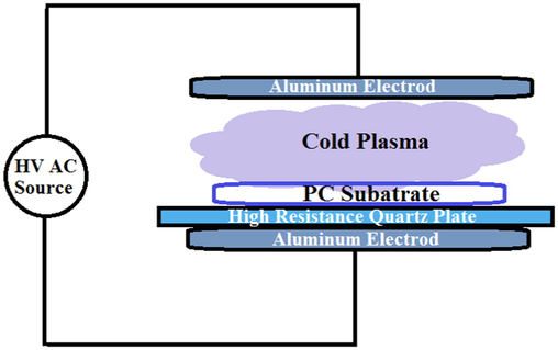
Schematic of the dielectric barrier discharge (DBD) system used for plasma treatment of PC substrates at ambient conditions.
2.4 Films characterization
In order to investigate the structural characteristics of the films, grazing incidence XRD (GI-XRD) pattern was taken. The Asenware AW-DX300 with copper cathode at voltage of 40 kV and current of 30 mA in the angle range of 0.5-40° was used. X-ray powder diffraction data (XRD) were collected on Bruker D8 Advance diffractometer with Cu K-α radiation with a fixed time counting of 32 s at 298 K. Powder samples were obtained from sols heat treated at 150 °C. A Philips EM420 TEM (FEI Company, Hillsboro, OR) was used to investigation the nanohybrid prepared sol in liquid form. In order to investigate the surface morphology of the films and scratches, the field emission scanning electron microscopy (FE-SEM, Hitachi S4160, cold field emission, voltage 15 kV) was used. The distributions of Al, C, and Si atoms in nanohybrid thin films were studied by energy-dispersive X-ray spectroscopy, EDX mapping (INCA Penta FET × 3, Oxford, U.K.). In order to evaluate the chemical composition of the films the Attenuated total reflection, Infrared Fourier Transform Spectroscopy (ATR-FTIR, Perkin Elmer Model Specuum400) was used in the wavenumber range from 4000 to 500 cm−1. The transmittance spectra of the uncoated, plasma treated and coated PC samples were measured by diffuse reflectance ultraviolet–visible (UV/vis) spectroscopy (Shimadzu MPC-3100) at the wavelength range of 400–750 nm at room temperature. For investigating the refractive index and thicknesses was used a spectroscopic ellipsometer (Sentech-SE800) with an incidence angle of 70°. In order to study the wettability characteristics of the plasma treated PC substrates, the water contact angles (WCA) were measured by a camera (Dino-lite, AM-4515 T8-Edge). In order to evaluate the scratch resistance (known as scratch or pencil hardness) of the films, a commercial pencil hardness tester was used. The test was applied according to ASTM D3363 Standard, applying a vertical force of 750 g at 45° to the horizontal placed coated substrate by a pencil moving over the film. The hardness of the pencil leads varies from the hardest to the softest (6H-6B). The reported pencil hardness degree is the same number of the pencil at which no pencil impression was found. Each pencil test was repeated 5 times on each sample for more assurance. Adhesion of the coating onto the substrate was investigated by cross-cut method according to the ASTM D3359-09e2 standard, which identifies the adhesion strength between films and substrates by a lattice pattern cut on the films. Then a pressure sensitive tape is attached to the cross pattern and pulled off. Adhesion is rated from 5B to 0B depending on the removal extent of the coating. 5B indicates no loss and so excellent adhesion and 0B indicates the removal of the most of the film from the substrate (over 65 % coating removal). For evaluating the scratch resistance of the films, severe eraser test was applied according to the MIL-E-12397B standard. The eraser has high grade abrasive fillers (50 vol%) that applies a constant vertical load of 1134 g to the film. The eraser is rubbed on the films for ten strokes in 3 cm length and then the scratch marks are examined by optical microscopy. The appearance of the thin films was investigated using an optical microscopy of Olympus PMEU-F200 model. Images were taken by a Micropublisher 3.3 RTV camera.
3 Results and discussion
3.1 DBD preparation of the PC substrates
Plasma state (glow discharge) is a mixture of ions, UV photons, activated free radicals, energetic electrons and excited molecules. Cold plasma is generated by gaseous electric discharge that provides a source of high-energy electrons at low temperature that is suitable for heat sensitive polymer materials treatment. Polymers have naturally low surface free energy due to the lack of polar components on their surfaces. Treating of polymer surfaces with cold plasma techniques increases their surface free energy by grafting polar functional groups such as carbonyl (C⚌O) and carboxyl (—COOH) onto their surfaces (Guragain, 2021). In this work, DBD was used for treating the PC substrates. Fig. 2(a-e) indicates the water contact angles (WCA) on the PC substrates before and after plasma treatment at different treatment times. It can be seen that the initial WCA of the untreated PC was about 73.24°. The WCA values reduced considerably after 45 s plasma treatment to 6.32°. PC became more hydrophilic due to the plasma treatment and the decrease in WCA was attributed to the rate of chemical changes taking place. No significant changes in WCA were detected with increase in plasma exposure time. It is obvious that the contact angle reduction by DBD in open air was higher than PC treated by atmospheric air (43°) (Raju, 2012) and in N2 plasma (60° for 1 min treatment) (Kostov, 2014). It proved that more wettability was obtained by DBD system used in this work. Reduction of the WCA stemmed from the increase of polymer surface free energy that was mainly arisen from the increase of its polar components on the surface. In other words the polar components played an important role in the enhancement of the surface energy of the treated polymers. The chemical binding energy of polymers is less than 10 eV and the mean electron energy is in the range of 1–10 eV. So energetic particles in plasma can easily break the chemical bonds of polymers (Kostov, 2014). The bombardment of reactive fragments caused simultaneous surface etching and oxidation. Subsequently, created free radicals on the surface coupled with active species from the plasma to form polar groups. The higher surface free energy and lower WCA led to better adhesion between polymer and thin films. Before plasma treatment the adhesion of thin films on raw untreated PC substrates was very weak. In other words, when the substrate was sloped all of the sol dripped away from it and no coating was made on it. There was no sol left on the substrate. After plasma treatment due to polar groups made on the surface adhesion was improved (Raju, 2012; Gururaj, 2011; Hofrichter et al., 2002).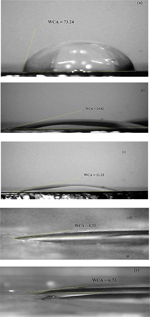
Water contact angle (WCA) measurements of: (a) un-plasma-treated PC and plasma-treated PC for (b) 15 sec, (c) 30 sec, (d) 45 sec and (e) 1 min.
Fig. 3 shows the ATR-FTIR spectra of the PC substrates before and after plasma treatment. As can be seen the intensity of the bands increased significantly. The enhancement of the surface free energy was due to the oxygenation of the polymer surface by the plasma treatment. Enhancement of polar components of the surface carried out by reactions between the plasma energetic species and the polymer chain introducing polar oxygen groups on the surface. The breakage of the weaker C—C and C—H bonds on the polymer surface can be effectively done by the energetic pieces (electrons and UV photon) present in the plasma. Specially plasma treatment in open air contains abundant reactive oxygen atoms which can react with the loose bonds on the polymer surface creating different parts such as mono-oxidized C—O, bi-oxidized C⚌O or O—C—O carbons (Kostov, 2014). Indeed the improved wettability and more hydrophilicity of the DBD treated PC came from these oxygen containing polar groups that were generated through the plasma treatment (Gururaj, 2011; Subedi, et al., 2008). The characteristic absorption bonds at 1010, 1767 and 2966 cm−1 were attributed to C—O, C⚌O carbonate group vibration and the stretching vibration of C—H bonds of CH3 groups, respectively. The intensity of the absorption bonds of the C—O and C⚌O increased due to plasma treatment (Koh, 2002; Vijayalakshmi, 2011). The band at 1593 cm−1 was related to the stretching C⚌C of aromatic groups of PC substrate. The reduction of water contact angle was stemmed from the polar functional groups that were made on the PC surface by plasma treatment.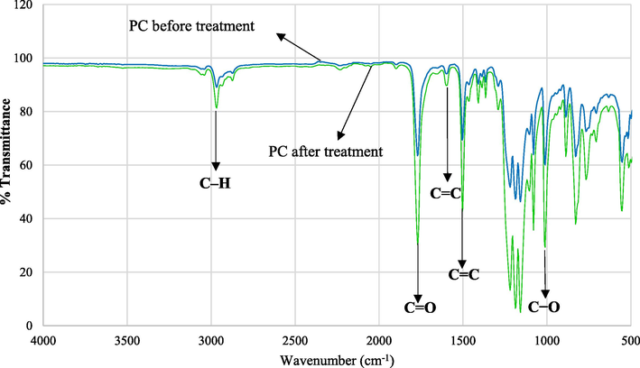
ATR-FTIR spectra of PC substrates before and after plasma treatment for 45 sec.
Fig. 4 indicates the transmittance spectra of the PC before and after plasma treatment at different treatment times. The PC optical transparency remained almost constant after plasma treatment. The transmittance variations after plasma treatment were so negligible (below 5 %) that indicated the plasma treatment had almost no effect on the PC transmittance. Fig. 5 shows FE-SEM images of the PC (a) before and (b) after DBD treatment. It is clear that PC surface was completely smooth but after treatment being rough. The etching process was conducted through the physical removal of molecules by the impact of energetic active pieces and by the breaking up of loose bonds (Soliman, 2014. 2014.).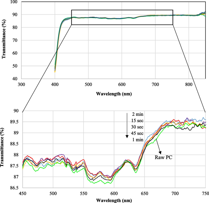
Transmittance spectra of PC substrates before and after plasma treatment for different times from 15 sec to 2 min.
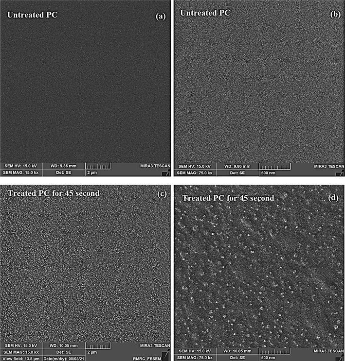
FE-SEM micrographs of: (a-b) PC before plasma treatment and (c-d) PC after 45 sec plasma treatment.
3.2 Sol-gel thin films evaluation
3.2.1 XRD results
The GI-XRD pattern of thin film and XRD pattern of dried sols are shown in Fig. 6. The peaks are characterized on the patterns. It can be seen that the GI-XRD pattern, due to low film thickness, belongs to the PC substrate and the peaks come from the substrate. The only peak detected in Fig. 6 (a) at 2θ = 16.8° is attributed to the Bisphenol A component with reference code of 00–022-1755 that is arisen form substrate and indicates the amorphous nature of PC (Mohamed and Abdel-Kader, 2020). For this reason, the XRD pattern of the dried sol are taken. The XRD pattern shows there are some sharp peaks that are identified precisely. However, low intensity of the peaks suggestes that the nanocrystals formed and dispersed in an amorphous matrix. The amorphous nature of the prepared matrix is predictable regarding the synthesis method and applied low temperatures as reported by others (Rahoui et al., 2013; Sowntharya and Subasri, 2013).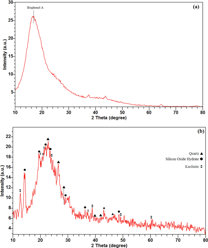
X-ray patterns of: (a) GI-XRD pattern of the prepared thin film and (b) XRD pattern of dried A2 sol.
The XRD pattern shown in Fig. 6(b) proves the formation of silicone oxide (SiO2) with the hexagonal chemical structure of quartz. The suggested reference code for the identified quartz is 01–079-1915. The peaks emerged at 2θ = 22.8°, 26.5°, 28.5°, 39.7°, 41.9°, 43.0° and 46.3° are attributed to (1 0 0), (0 1 1), (1 0 1), (1 1 0), (0 1 2), (1 1 1) and (2 0 0) respectively. The corresponding peaks for silicon oxide hydrate known as silica gel with the chemical formula of H2Si2O5 with the reference code of 00–020-1049 is identified. The emerged peaks at 2θ = 14.22°, 19.3°, 21.9°, 23.6°, 29.0°, 36.2° and 48.6° are attributed to silicon oxide hydrate. As well as, the compound phase including Si and Al atoms is detected. For example, aluminum silicate hydrate with the kaolinite mineral name and Al2Si2O5(OH)4 chemical formula is characterized. The reference code is 00–001-0527. The appeared peaks at 2θ = 12.6°, 19.7°, 20.7°, 21.2°, 23.9°, 37.3°, 38.4°, 49.2° and 60.2° are attributed to (0 0 1), (0 2 0), (1 1 0), (-1–11), (0 2 2), (0 2 5), (1–31), (-2–32) and ( −1 3 4) respectively.
3.2.2 TEM morphological investigation
Morphology and particle size analyses of the nanohybrid sol is conducted by TEM. TEM micrographs are took from liquid sol. The liquid sol of the composition of A2 (as mentioned in the Table 2) is attenuated by water and then used for taking micrographs. Sample preparation is done just by attenuating the liquid sol by water. Fig. 7 indicates TEM images of nanohybrid sol with different magnifications. It can be seen that the formed nanoparticles were uniform with diameters of ∼ 20 nm. These are some agglomerated nanoparticles that can be attributed to higher surface energy induced by hydroxyl groups (Abdollahi, 2014).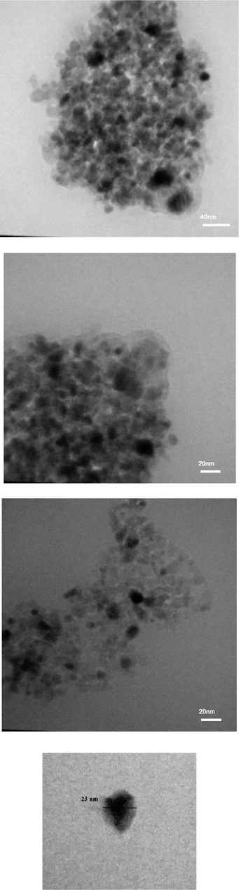
TEM images of sol–gel prepared nanohybrid A2 sol with different magnifications.
3.2.3 ATR-FTIR results
ATR-FTIR method is used for studying the chemical compositions of the films. Fig. 8 shows the obtained spectra from dried sols at different aging time (fresh, 2, 4 and 6 days) to investigate the aging time effect on the films. The sols ratios effects is reported in our previous paper (Kiomarsipour, 2023). For more comparison the IR spectrum from dried TEOS + GPTMS sol without ATB is taken. The broad weak band presented at about 3200–3600 cm−1 can be attributed to stretching vibration of —OH groups. The corresponding bending vibration is emerged at 1636 cm−1. The C—H (CH2) bonds of the GPTMS can absorb at 2939 cm−1 and the observed band at 1280 cm−1 can be assigned to the in-plane bending of C—H vibration. The carbonyl group C⚌O stretching vibration band is observed at 1716 cm−1 (Chen et al., 2013). The stretching and symmetric bending of CH3 groups bands are seen at 2874 cm−1 and 1473 cm−1 (Soloukhin, 2002). These C—H groups are from the glycidoxypropyl group of GPTMS. The Si—O—Si stretching vibration band at about 1040 cm−1 proves the nanohybrid nature of the sols and occurrence of the condensation reaction between silanols. The band at 555 cm−1 (generally in the range of 510–680 cm−1) can be assigned to the stretching of Si—O—Si bonds (Handke and Kowalewska, 2011; Handke et al., 2011). It was reported that the epoxy ring in the GPTMS silane presented at 960–810 cm−1 (asymmetrical ring stretching) (Liu and Berg, 2007). In TEOS + GPTMS spectrum the band of epoxy ring can be seen at around 960 cm−1 but in other samples there is not. It is concluded that the ATB led to opening epoxy ring and catalyzed the ring opening reaction (Liu and Berg, 2007). As reported by Barrios et al. (Hernández-Barrios, 2017) changes occurred in the coatings after 28 days aging were intangible so it was reasonable that the changes in our coatings during 6 days are insignificant. The similarity of the spectra suggests the ability of obtaining suitable optical and mechanical properties within a wide range of chemical compositions.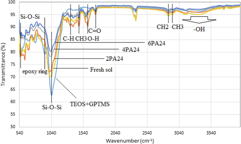
ATR-FTIR spectra of dried TEOS + GPTMS and A24 at different aging times.
3.2.4 UV/vis results
The photos of prepared sols and coatings are indicated in Fig. 9(a,b). The obtained sols were completely transparent and homogenous without phase separation and the deposited coatings were uniform, transparent and homogenous. The prepared sols remained unchanged after 18 months. The optical images of the films are shown in Fig. S1. It is clear that the coatings were free of cracks and delamination. The suitable ratios of inorganic/organic parts led to good adhesion and flexibility. The presence of GPTMS prevented cracking due to drying stresses and improved the films flexibility (Hajfarajzadeh et al., 2019). Regarding the epoxy group present in the GPTMS, it plays like the organic part in hybrid coating systems. The epoxy group promotes the coating adhesion, its flexibility and scratch resistance. In other words, organosilanes are an alternative to organic polymer binders in the hybrid coatings. These organo-alkoxysilanes precursors have organo-functional silane R’n-Si(OR)4-n, where R’ is an organic functional group (R’) such as amine, vinyl, epoxy, etc. The incorporation of the organic component R’ in the sol–gel coating systems allows to control the density and flexibility of the sol–gel network. This component leads to create thicker film without cracking (Perrin et al., 2020; Zandi-Zand et al., 2005; Chu et al., 1997; Hernández-Barrios, 2020; Robertson, 2003).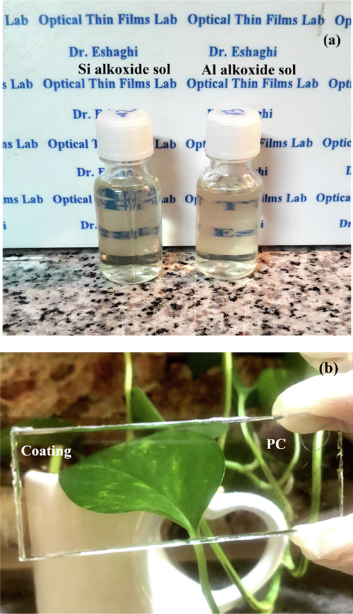
Optical photographs of: (a) transparent silica and aluminum sols and (b) dip-coated PC substrate.
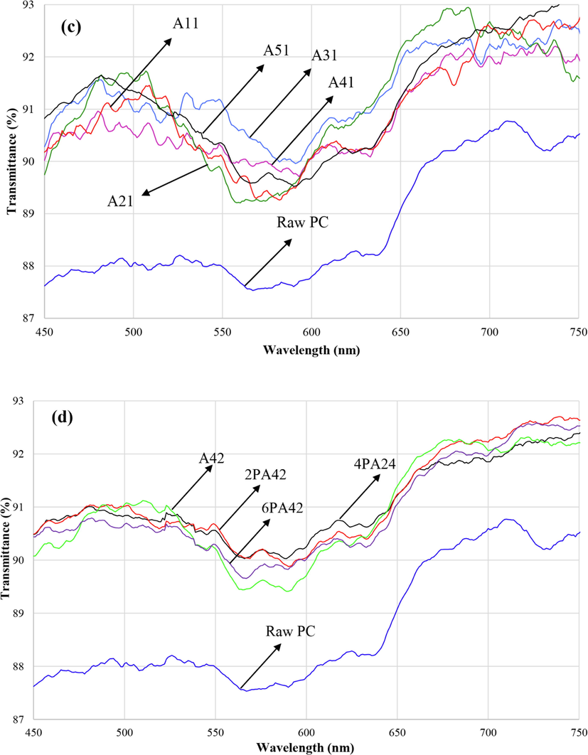
The transmittance spectra of the PC substrate and TEOS + GPTMS sol–gel coating are shown in Fig. 10(a). The transmittance spectra of the nanohybrid coatings containing Si and Al nanoparticles are indicated in Fig. 10(b-d) for different conditions (temperatures, ratios and aging times). It is clear that the average %T increased from 86 % for uncoated PC to 89 % for coated PC. The preparation of new structure of Si and Al atoms leads to less refractive index than SiO2 structure. The differences between transmittance spectra are insignificant and they are similar together. Because the chemical composition through all of the samples were kept constant their transmittance spectra showed similar behavior.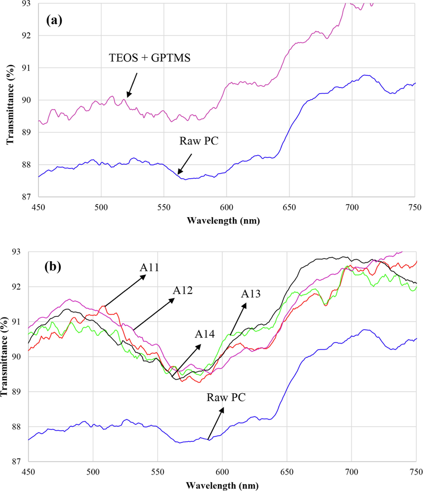
Transmission spectra of the sol–gel films: (a) TEOS + GPTMS coating compared with raw PC, (b) sol–gel coatings prepared at different temperatures, (c) sol–gel coatings with different sol ratios and (d) sol–gel coatings prepared at different times.
Transmission spectra of the sol–gel films: (a) TEOS + GPTMS coating compared with raw PC, (b) sol–gel coatings prepared at different temperatures, (c) sol–gel coatings with different sol ratios and (d) sol–gel coatings prepared at different times.
In order to increase the transparency, the refractive index of the coating must be less than that of the PC substrate (Chen et al., 2013). The refractive index curve versus wavelength of 4PA24 sample is indicated in Fig. 11. It is clear that refractive index of sol–gel coating was 1.481 at 775 nm and the index of PC substrate was 1.58. The enhancement of optical transparency of the nanohybrid coatings emanated of the combined effects of Si and Al atoms resulting in low refractive index (Li, 2015). This fact finally led to decrease the reflection of the incident light and increase the transmittance.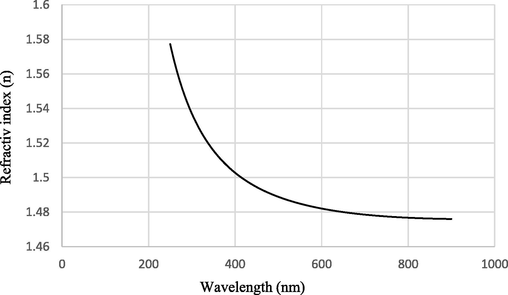
Refractive index (n) versus wavelength of 4PA24 sample.
3.2.5 FE-SEM and optical micrographs
The optical micrographs of the films after 10 strokes are shown in Fig. 12. The images belong to various coating compositions in order to show that all of the prepared coatings have the ability to improve the PC scratch resistance. The scratch marks were clear on the bare PC while there were a few marks on the coatings.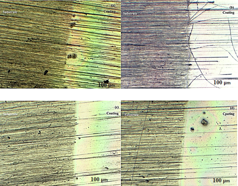
Optical micrographs of the sol–gel prepared films after 10 strokes of rubbing eraser: (a) TEOS + GPTMS coating, (b) A14. (c) 4PA24, (d) 2PA32.
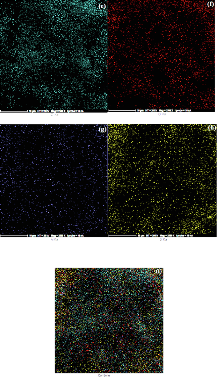
The FE-SEM images and the EDS analysis result of the sol–gel coating are indicated in Fig. 13. Fig. 13(a-b) shows that the samples were smooth, uniform without any agglomerates, cracks, holes and delamination. The abrasion tracks of eraser strokes can be seen clearly on the uncoated PC substrate (Fig. 13(c)) while the coated area remained undamaged. It can be found that the sol–gel coatings improved the PC scratch resistance and enabled the substrate to endure scratch damages. Fig. 13(d) indicates the EDS analysis result. The presence of aluminum and silicon elements in the films are clear. It is clear that the scratch resistance improved significantly for each composition. Fig. 13(e-i) shows series of SEM elemental mapping images of the as-synthesized samples proving that Si, Al, O and C atoms were evenly dispersed and distributed throughout the composite samples. The uniform dispersion of these elements suggested that the nanoparticles were incorporated successful into the nanohybrid thin films. The sol–gel prepared coatings included well dispersed of all atoms that interlocked throughout the film uniformly.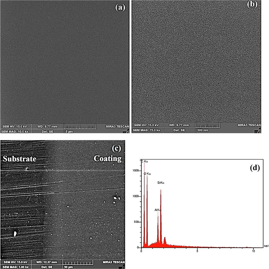
FE-SEM micrographs of 4PA24 coating: (a,b) before scratch test, (c) after 10 eraser strokes and (d) the EDS elemental pattern, (e) C mapping, (f) Si mapping, (g) Al mapping, (h) O mapping and (i) their combination.
FE-SEM micrographs of 4PA24 coating: (a,b) before scratch test, (c) after 10 eraser strokes and (d) the EDS elemental pattern, (e) C mapping, (f) Si mapping, (g) Al mapping, (h) O mapping and (i) their combination.
It has been shown that the tribological performance improved by plasma treatment. Because the sol–gel films had ceramic nature and the ceramic-based oxide phase causes to decrease shear stresses and the adhesion between two contacting surfaces maybe lead to better abrasion properties (Tekdir and Yetim, 2021; Turalıoğlu, 2021).
3.2.6 Adhesion results
Adhesion test was conducted by cross cut method that a pressure sensitive tape was applied on the cross pattern on the coating. It was clear that the films had good adhesion (5B) despite coatings aged for 6 days. Their adhesion reduced to 3B-4B due to more cross linking occurred in the coating. The good adhesion strength resulted by DBD treatment of the PC. Fig. S2 shows optical micrographs after the adhesion test.
Tiringer et al. (Tiringer, 2021) studied the effect of chemistry, roughness and wettability of the different pre-treated surfaces on the adhesion of a hybrid sol–gel coating by measuring the pull-off strengths. They used four different substrates pretreatments (bare, HNO3, KOH and boiling water). They showed that the highest pull-off strength was obtained after boiling DI water pretreatment, that can be related to the formation of a pseudoboehmite layer. They found that more surface roughness led to more adhesion strength (Robertson, 2003).
3.2.7 Pencil hardness results
Pencil hardness test is a good measurement for evaluating coating's scratch resistance under heavy load. Describing the scratch mechanisms of a thin film on a soft substrate under a pencil lead is a complicated issue. In order to evaluate the scratch resistance, pencil hardness tests was carried out according to the ASTM D3363 standard. The optical micrographs of the pencil scratch are shown in Fig. S3. The pencil hardness is the grade of the pencil that does not leave a visible scratch mark on the coating. The pencil hardness of the PC substrates (4B) increased to 3H for the sample 4PA24. Improvement the PC hardness from 4B to 3H (8 grade increment) was very incredible. This pencil hardness increment obtained with mono-layer coating with thickness of about 775 nm. One of the most effective factors on the pencil hardness is the film thickness. Increasing coating thickness leads to increase the pencil hardness. The previous reports showed the pencil hardness lower than 1H in the thin films (Chen, 2008). In acrylates reinforced by colloidal silica hardness of 5/6H was obtained by 50 µm thickness (Barletta, 2016) and 3H with 15 µm thickness by the nanohybrid coatings on PC (Sowntharya, 2012).
All the hybrid coatings deposited on the PC exhibited the pencil hardness of HB at thickness of 1.7 µm (Suriano, 2017) and H for colloidal silica content of 36.0 vol% with thickness within the range of 5 ± 0.5 μm (Chen, 2008). The incorporation of Al2O3 and ZrO2 nanoparticles in the TEOS-GPTMS sol system improved the pencil hardness of coatings from 2H (pristine PC) to 2H at 5 µm coating thickness (Chantarachindawong, 2016) and up to 3H with 19.6 µm coating thickness (Shin, 2009). The pencil hardness in nanohybrid coatings made of titanium tetraisopropoxide and an acrylic modified silane was 3H at 7.2 µm thickness (Sowntharya and Subasri, 2013). It seems that the boehmite nanoparticles led to a higher hardness and scratch resistance in the sol–gel prepared coatings on the PC (Schottner et al., 2003).
3.2.8 Mechanisms of coating failure
Fig. S4 shows the optical micrographs of the typical pencil scratch marks with 5H pencil. It can be seen that the coating cracking was the dominant mode of the failure. It can be concluded from the fracture patterns that coating damage was caused by tensile cracking behind the indenter. There was little or no coating detachment at either the leading edge or the trailing end of the scratch, indicating that the adhesion between the film and the substrate was very strong due to the plasma activated PC surface.
The failure mechanisms of films have been completely expressed by Wu et al. (Wu, 2008). After applying hard pencil, the static pressure imposed by sharp narrow pencil tip on the small contact area caused to gouge creation. Movement of the hard pencil lead on the film led to the creation of the cylindrical scratch mark. The gouge failure caused by the hardness of the coating and the strength of the substrate. Micro-cracks are present on the pencil trail both inside and outside of the impression. The film failure results by film cracking and substrate deformation. In gouge failure mechanism the film endures tensile stress while the PC polymeric substrate undergoes a plastic deformation. The plastic deformation starts as soon as the pressure imposed by pencil tip exceeds the substrate yield strength and consequently a gouge failure is formed on the surface coating. The high vertical pressure exerted by pencil lead led to plastic deformation of substrate at the front edge. Behind the pencil tip, the film undergoes tensile stress that is produced by the friction effect. Coatings will be cracked if this tensile stress exceeds the strength of the coating material. In the meantime, of scratch formation, the tensile stress created in the film outside and near the scratch impression by substrate plastic deformation. The good adhesion strength between the films and plasma treated PC substrates led to no film delamination (Wu, 2008). It must be noticed that the pencil hardness grade is similar in thin coatings (≥5 μm thickness) and the improvement of pencil hardness is very limited (Wu, 2008).
3.3 Conclusion
The binary-oxide sol–gel system was used to improve PC substrate mechanical and optical properties. The effect of sol ratio, time and temperature on the thin film’s properties were studied. The obtained improvements were as follow: 1- higher average optical transmittance (89 %) than the raw PC (86 %), 2- good adhesion to the PC (5B) and 3- more pencil hardness (3H) than raw PC (4B). The temperature effect was negligible indicated that coatings can cross linked in low temperatures. The new sol–gel hybrid structure made of interlocked Si and Al atoms led to lower refractive index (1.481) than silica hybrid coatings.
Acknowledgements
The present research was financed by the Iran National Science Foundation (INSF), according to Grant number 99021712, and the authors would like to express their acknowledgments to Iran National Science Foundation (INSF).
References
- Anticorrosive coatings prepared using epoxy–silica hybrid nanocomposite materials. Ind. Eng. Chem. Res.. 2014;27)53:10858-10869.
- [Google Scholar]
- Wear characterization of chromium PVD coatings on polymeric substrate for automotive optical components. Coatings. 2021;11(5):555.
- [Google Scholar]
- Hard transparent coatings on thermoplastic polycarbonate. Prog. Org. Coat.. 2016;90:178-186.
- [Google Scholar]
- Effect of cerium on structure modifications of a hybrid sol–gel coating, its mechanical properties and anti-corrosion behavior. Mater. Res. Bull.. 2012;47(11):3170-3176.
- [Google Scholar]
- Hard coatings for CR-39 based on Al2O3–ZrO2 3-glycidoxypropyltrimethoxysilane (GPTMS) and tetraethoxysilane (TEOS) nanocomposites. J. Sol-Gel Sci. Technol.. 2016;79(1):190-200.
- [Google Scholar]
- Scratch resistance of brittle thin films on compliant substrates. Mater. Sci. Eng. A. 2008;493(1–2):292-298.
- [Google Scholar]
- The preparation and characterization of abrasion-resistant coatings on polycarbonate. J. Coat. Technol. Res.. 2013;10(1):79-86.
- [Google Scholar]
- Use of (glycidoxypropyl) trimethoxysilane as a binder in colloidal silica coatings. Chem. Mater.. 1997;9(11):2577-2582.
- [Google Scholar]
- Diamond-like carbon films deposited on polymers by plasma-enhanced chemical vapor deposition. Surf. Coat. Technol.. 2003;174:1024-1028.
- [Google Scholar]
- Diamond-like carbon films deposited on polycarbonates by plasma-enhanced chemical vapor deposition. Thin Solid Films. 2008;516(12):4053-4058.
- [Google Scholar]
- Improvement of hydrophilicity of polypropylene film by dielectric barrier discharge generated in air at atmospheric pressure. Rev. Adhesion Adhesives. 2021;9(1):153-166.
- [Google Scholar]
- Effect of plasma pretreatment on adhesion and mechanical properties of UV-curable coatings on plastics. Appl. Surf. Sci.. 2011;257(9):4360-4364.
- [Google Scholar]
- Technical feasibility study on polycarbonate solar panels. Sol. Energy Mater. Sol. Cells. 2004;84(1–4):105-115.
- [Google Scholar]
- Fabrication and characterization of an optical nano-hybrid sol-gel derived thin film on the PMMA substrate. J. Adv. Mater. Eng. (Esteghlal). 2019;37(4):101-112.
- [Google Scholar]
- Siloxane and silsesquioxane molecules—Precursors for silicate materials. Spectrochim. Acta A Mol. Biomol. Spectrosc.. 2011;79(4):749-757.
- [Google Scholar]
- Amorphous SiCxOy coatings from ladder-like polysilsesquioxanes. J. Mol. Struct.. 2011;993(1–3):193-197.
- [Google Scholar]
- Effect of the catalyst concentration, the immersion time and the aging time on the morphology, composition and corrosion performance of TEOS-GPTMS sol-gel coatings deposited on the AZ31 magnesium alloy. Surf. Coat. Technol.. 2017;325:257-269.
- [Google Scholar]
- Effect of cerium on the physicochemical and anticorrosive features of TEOS-GPTMS sol-gel coatings deposited on the AZ31 magnesium alloy. Surf. Interfaces. 2020;21:100671
- [Google Scholar]
- Plasma treatment of polycarbonate for improved adhesion. J. Vac. Sci. Technol. A. 2002;20(1):245-250.
- [Google Scholar]
- A robust transparent protective hard-coating material using physicochemically-incorporated silica nanoparticles and organosiloxanes. Prog. Org. Coat.. 2017;105:330-335.
- [Google Scholar]
- Properties of AZO thin films for solar cells deposited on polycarbonate substrates. J. Korean Phys. Soc.. 2009;55(5):1945-1949.
- [Google Scholar]
- Investigation of upward speed and thickness effects on optical and mechanical properties of hard transparent thin films deposited on polycarbonate substrate. Prog. Org. Coat.. 2023;177:107405
- [Google Scholar]
- Altering a polymer surface chemical structure by an ion-assisted reaction. J. Adhes. Sci. Technol.. 2002;16(2):129-142.
- [Google Scholar]
- Treatment of polycarbonate by dielectric barrier discharge (DBD) at atmospheric pressure. J. Phys.: Conf. Ser. 2014 IOP Publishing
- [Google Scholar]
- Scratch-resistant sol–gel coatings on pristine polycarbonate. New J. Chem.. 2015;39(11):8302-8310.
- [Google Scholar]
- Solvent-free zirconia nanofluids/silica single-layer multifunctional hybrid coatings. Colloids Surf. A Physicochem. Eng. Asp. 2015;464:26-32.
- [Google Scholar]
- Broadband antireflective and superhydrophobic coatings for solar cells. Mater. Today Energy. 2019;12:348-355.
- [Google Scholar]
- An aqueous sol–gel route to prepare organic–inorganic hybrid materials. J. Mater. Chem.. 2007;17(41):4430-4435.
- [Google Scholar]
- Polycarbonate reinforced with silica nanoparticles. Polym. Bull.. 2011;66(7):991-1004.
- [Google Scholar]
- SnS2/polycarbonate nanocomposites: structural and optical characterizations. J. Inorg. Organomet. Polym Mater.. 2020;30(6):2289-2298.
- [Google Scholar]
- Relation between the corrosion resistance and the chemical structure of hybrid sol-gel coatings with interlinked inorganic-organic network. Prog. Org. Coat.. 2020;141:105532
- [Google Scholar]
- Effect of thermal treatment on mechanical and tribological properties of hybrid coatings deposited by sol–gel route on stainless steel. Surf. Coat. Technol.. 2013;235:15-23.
- [Google Scholar]
- Effect of plasma pretreatment on adhesion and mechanical properties of sol-gel nanocomposite coatings on polycarbonate. Compos. Interfaces. 2012;19(3–4):259-270.
- [Google Scholar]
- Mechanical and thermal properties of organic/inorganic hybrid coatings. J. Sol-Gel Sci. Technol.. 2003;26(1):291-295.
- [Google Scholar]
- Hard coatings by plasma CVD on polycarbonate for automotive and optical applications. Thin Solid Films. 2006;502(1–2):270-274.
- [Google Scholar]
- Scratch and abrasion resistant coatings on plastic lenses—state of the art, current developments and perspectives. J. Sol-Gel Sci. Technol.. 2003;27(1):71-79.
- [Google Scholar]
- Hard coatings on polycarbonate plate by sol–gel reactions of melamine derivative, poly (vinyl alcohol), and silicates. J. Ind. Eng. Chem.. 2009;15(2):238-242.
- [Google Scholar]
- Limiting the migration of bisphenol A from polycarbonate using Dielectric Barrier Discharge. Open J. Synthesis Theory Applications 2014. 2014.
- [Google Scholar]
- Mechanical properties of silica–(meth) acrylate hybrid coatings on polycarbonate substrate. Polymer. 2002;43(23):6169-6181.
- [Google Scholar]
- Investigations on the mechanical properties of hybrid nanocomposite hard coatings on polycarbonate. Ceram. Int.. 2012;38(5):4221-4228.
- [Google Scholar]
- A comparative study of different curing techniques for SiO2–TiO2 hybrid coatings on polycarbonate. Ceram. Int.. 2013;39(4):4689-4693.
- [Google Scholar]
- Subedi, D., et al., 2008. Plasma treatment at low pressure for the enhancement of wettability of polycarbonate.
- Fluorinated zirconia-based sol-gel hybrid coatings on polycarbonate with high durability and improved scratch resistance. Surf. Coat. Technol.. 2017;311:80-89.
- [Google Scholar]
- Additive manufacturing of multiple layered materials (Ti6Al4V/316L) and improving their tribological properties with glow discharge surface modification. Vacuum. 2021;184:109893
- [Google Scholar]
- Scrutinizing the importance of surface chemistry versus surface roughness for aluminium/sol-gel film adhesion. Surf. Interfaces. 2021;26:101417
- [Google Scholar]
- The tribological and corrosion properties of anodized Ti6Al4V/316L bimetallic structures manufactured by additive manufacturing. Surf. Coat. Technol.. 2021;405:126635
- [Google Scholar]
- Studies on modification of surface properties in polycarbonate (PC) film induced by DC glow discharge plasma. Int. J. Polym. Sci.. 2011;2011
- [Google Scholar]
- Transparent UV curable antistatic hybrid coatings on polycarbonate prepared by the sol–gel method. Prog. Org. Coat.. 2004;51(4):312-319.
- [Google Scholar]
- A study towards improving mechanical properties of sol–gel coatings for polycarbonate. Thin Solid Films. 2008;516(6):1056-1062.
- [Google Scholar]
- A parametric study on processing of scratch resistant hybrid sol–gel silica coatings on polycarbonate. Thin Solid Films. 2014;556:112-119.
- [Google Scholar]
- Organic–inorganic hybrid coatings for corrosion protection of 1050 aluminum alloy. J. Non Cryst. Solids. 2005;351(14–15):1307-1311.
- [Google Scholar]
- Silica based organic–inorganic hybrid nanocomposite coatings for corrosion protection. Prog. Org. Coat.. 2005;53(4):286-291.
- [Google Scholar]
- Sol–gel coatings for corrosion protection of metals. J. Mater. Chem.. 2005;15(48):5099-5111.
- [Google Scholar]
Appendix A
Supplementary material
Supplementary data to this article can be found online at https://doi.org/10.1016/j.arabjc.2023.104667.
Appendix A
Supplementary material
The following are the Supplementary data to this article:Supplementary data 1
Supplementary data 1


