

Translate this page into:
Preparation of polyaniline encapsulated acrylic resin microcapsules and its active corrosion protection of coating for magnesium alloy
⁎Corresponding author at: Sichuan University of Science and Engineering, Zigong 643000, China. zhangyingjun@hrbeu.edu.cn (Yingjun Zhang)
-
Received: ,
Accepted: ,
This article was originally published by Elsevier and was migrated to Scientific Scholar after the change of Publisher.
Peer review under responsibility of King Saud University. Production and hosting by Elsevier.
Abstract
Herein, novel microcapsules were designed and synthesized by emulsion polymerization and used for self-healing coating for magnesium alloy. Polyaniline (PANI) was used directly as a capsule shell, and thermoplastic acrylic resin was used as the core material. Polymerization processes of microcapsules were observed by optical microscopy, and some key polymerization parameters were discussed. Composite microcapsules were analyzed by scanning electron microscopy, infrared spectroscopy, and thermogravimetric analysis. The corrosion protection performance of microcapsule and epoxy varnish coatings with defect was tested by electrochemical impedance spectroscopy. Results showed that the microcapsule coating had a higher corrosion protection than epoxy varnish coating because capsule core acrylic resin could significantly improve the shield performance of the defect coating and capsule shell PANI could inhibit the corrosion reaction of magnesium alloy.
Keywords
Microcapsule
PANI
Magnesium alloy
Coating
Corrosion protection

1 Introduction
Self-healing technology was developed to improve the corrosion protection of organic coatings. One of the most important strategies to achieve self-healing is to use microcapsule hosting systems for encapsulation of repair agent, as first proposed by White et al. in 2001 (White et al., 2001). The outer layer of the microcapsule is called the capsule shell, and the inner repair agent is called the core material. The microcapsule containing the repair agent is typically embedded in the polymer matrix material. The repair agent is released and functions when cracks or defects appear in the coating, thereby suppressing corrosion.
From the latest reports, the core material includes corrosion inhibitors and monomers of polymers. The corrosion inhibitor can leach into the coating defect and inhibit the electrochemical reactions occurring at the exposed metal substrate. However, most of the chemical inhibitors can only retain the corrosion resistance for a short period. For long-term protection, polymeric healing agents are preferred because the crosslinking reaction between the monomer (healing agent) and curing agent at the damage site can repair the coating’s barrier property (Pulikkalparambil et al., 2018; Zhang et al., 2018). Epoxy resin (EP) and their hardeners (Cosco et al., 2006; Siva and Sathiyanarayanan, 2015), namely, dicyclopentadiene monomers, polydimethylsiloxane prepolymers (Cho et al., 2009), isophorone diisocyanate (Wang et al., 2014); flax oil (Leal et al., 2017; Lang and Zhou, 2017), and tung oil (Li et al., 2017), have been successfully used as healing agents.
Compared with the study of the core material (repair agent), the capsule shell material has received less attention. In recent studies, polystyrene (Dong et al., 2015), polyurethane (Beglarigale et al., 2018), melamine formaldehyde resin (Li et al., 2016), and urea–formaldehyde resin (Dong et al., 2016) were the most selected shell materials for encapsulation healing agents due to their good mechanical properties (Lv et al., 2020). These shell materials are also polymers that play key roles in the protection of the core material (healing agents) before rupture. Therefore, healing agents only work when the capsule shell is ruptured. When in complete form and the healing agents will not flow out, the microcapsule cannot self-heal even if small defects, which result in corrosion, are present. Notably, electrochemical reactions are immediately inhibited when the capsule shell consists of certain corrosion inhibition materials. Liu et al. successfully prepared PUF MCs poly(urea–formaldehyde)-shelled microcapsules with inhibited adhered corrosion inhibit or nano-CeO2 to improve the coating’s performance (Liu et al., 2022).
Polyaniline (PANI) is one of the most investigated conducting polymers due to its facile synthesis, unique doping characteristics, and environmental stability. Our previous work also found that PANI coating exerts good corrosion protection on the surface of magnesium alloy and mild steel (Zhang et al., 2011; Zhang et al., 2017). Several efforts have been exerted to introduce PANI to shell materials of microcapsules using a two-shell structured inhibitor-loaded PANI through a traditional method (Han et al., 2022). After reviewing and analyzing relevant literature, different morphologies of PANI, such as hollow spheres, capsules (Ma et al., 2015), nanofibers (Ma et al., 2016), microfibers (Wang et al., 2016), and nano-ribbons and nanoplates (Adhikari et al., 2022), have been obtained by employing hard templates, soft templates, and other effective means (Ma et al., 2016). PANI has also been explored as a membrane material (Alhweij et al., 2021; Xu et al., 2022). The innovation of this paper is that PANI was used directly as a capsule shell material. Therefore, PANI played two important roles: encapsulating the core and corrosion inhibition.
This research aimed to find the optimal conditions for the preparation of micro-capsules with PANI as a shell and homemade thermoplastic acrylic resin as the core by emulsion polymerization for use in anticorrosive coatings. The structure and performance of the microcapsules were analyzed, and the corrosion protection effect of these microcapsules was proven.
2 Experimental
2.1 Materials
Aniline was purchased from Chengdu Colon Chemical Co., Ltd. and distilled under vacuum before use. Ammonium persulfate (APS, 98%) was obtained from Shanghai Aladdin Biochemical Technology Co., Ltd. Hydrochloric acid (HCl, 36–38%) was supplied from Chongqing Chuandong Chemical Co., Ltd. Ammonia (NH3(aq), AR), n-butyl alcohol (AR), xylene (Xyl, AR), and polyvinylpyrrolidone-K30 (PVP, AR) were obtained from Chengdu Colon Chemical Co., Ltd. Polyvinyl alcohol (PVA, ≥98%) was purchased from Sinopharm Chemical Reagent Co., Ltd. EP was supplied from Nantong Star Synthetic Materials Co., Ltd. Acrylic resin was synthesized in the lab, and some basic properties are listed in Table 1.
Solid Content (wt.%)
pH
Viscosity (mPa.s)
Curing time (h)
13.3
3.5 ∼ 4
3.4
5.2
Magnesium alloy AZ31B (chemical composition (wt.%): Al 2.5%-3.5%, Si 0.08%, Ca 0.04%, Zn 0.6%-1.4%, Mn 0.2%-1.0%, Cu 0.01%, Ni 0.001%, and Mg balance) was selected as the matrix material in the experiment.
2.2 Synthesis of PANI microcapsules
PANI-acrylic resin microcapsules were synthesized via emulsion polymerization, and the synthesis process was accomplished as follows. Fig. 1 shows a sketch map of the synthesized microcapsules. HCl was diluted with deionized water at a ratio of 1:1, and it was used to adjust the pH to 1–2 under stirring. The resulting product was called acidized aniline. Simultaneously, emulsifier PVP, protective colloid PVA solution, and acrylic resin were added to a round-bottom flask and stirred for a certain period. Next, we dropped 10% acidified aniline to a round-bottom flask at a constant stirring speed and left it to react for 1 h. Next, partial oxidant APS was also added and left to react for 1 h. The remaining 90% acidified aniline was added to react for 1 h. Then, the remaining oxidant APS was continuously added to a flask using a micro-pump, and the reaction was allowed to proceed for 12 h. The reaction mixture was filtered with a filter paper, and the powder was collected after rinsing with deionized water and dried at 40 °C in an oven.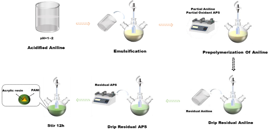
Sketch map of synthesized microcapsules.
2.3 Characterization of microcapsules
The morphology and surface features of the microcapsules were observed by optical microscopy (OM, SK2009H2, China). Scanning electron microscopy (SEM; VEGA 3SBU, Czech Republic) was employed to characterize the morphology of microcapsules and coating surfaces, and the microcapsules were vacuum-sprayed by gold before characterization by SEM. A Fourier-transform infrared spectrometer (FT-IR; Frontier Near, Platinum Elmer, USA) was used to determine whether the microcapsules were successfully encapsulated. Spectra were collected from 400 cm−1 to 4000 cm−1. Thermogravimetric analysis (TGA; STA-409PC, Germany) was used to measure type and mass of material lose during heating with time and temperature. The temperature was gradually increased to 800 °C at a heating rate of 10 °C/min during testing.
2.4 Preparation and characterization of coatings
The magnesium alloy matrix was polished with 180 and 400-mesh sandpaper and then cleaned with deionized water and anhydrous ethanol. Two kinds of coatings were prepared as follows. Firstly, epoxy varnish coating (EP) was prepared by adding 10 g of epoxy resin, 1.4 g of Xyl, and 0.6 g of n-butyl ester to a beaker and mixed properly followed by addition of 6 g of a curing while mixing thoroughly. The second, microcapsule coating was prepared by adding 10 g of epoxy resin, 0.2 g of polymerized PANI microcapsules, 1.4 g of Xyl, and 0.6 g of n-butyl ester to a beaker under mixing followed by the addition of 6 g of curing agent to the resulting mixed mixture to produce a uniform mixture. Next, about 6 g of curing agent was added to the beaker and mixed well with the mixture. A non-magnetic thickness gauge (PosiTector 6000, USA) was used to measure the thickness of the sample; the middle part of the sample was measured 10 times, and the average value was obtained. The sample with a coating thickness of about 90 μm was used for electrochemical testing.
Electrochemical impedance spectroscopy (EIS) was carried out on an electrochemical workstation (VersaSTAT3F, USA). In this work, 3.5 wt% NaCl solution was used as corrosion medium. A three-electrode system was used, in which platinum electrode was the auxiliary electrode, Ag/AgCl saturated potassium chloride electrode was the reference electrode, and magnesium alloy sample with coating was the working electrode. The AC impedance measurement frequency range was 0.01–100,000 Hz, and amplitude was 30 mV. To observe self-healing, before the test, a defect with 10 mm × 0.2 mm was made on the surfaces of the coating by a sharp blade and placed in the air for 24 h.
3 Results and discussion
3.1 Synthesis of PANI microcapsules
The formation of microcapsules described in section 2.2 was monitored by OM producing images captured at various stages of the micro capsulation process (Fig. 2). Fig. 2a displays the milky white emulsion that formed after 45 min (step 2, Fig. 1). The figure also shows the formation of a regular ball. Fig. 2b displays the images created after the addition of acidified aniline for 1 h (step 3). The solution turned light yellow, and portion of aniline was adsorbed on the emulsified ball surface. Fig. 2c presents a photo obtained after the addition of partial APS for 1 h (step 3). The surface of emulsion droplets was green, which indicates that portion of PANI had been polymerized on the surface of emulsion, which benefitted the deposition of subsequent aniline. Fig. 2d shows an image of the residual acidified aniline added after 30 min (step 4). Before dropping APS, the aniline monomer was continuously absorbed on the surface of the emulsion droplets. During the continuous dropping of APS, the color of the emulsion turned green and gradually deepened (step 5), which indicated that PANI was polymerized continually and deposited on the surface of emulsion droplets (Fig. 2e). When the reaction was completed (Fig. 2f), the emulsion was dark green, and several spherical capsules were formed.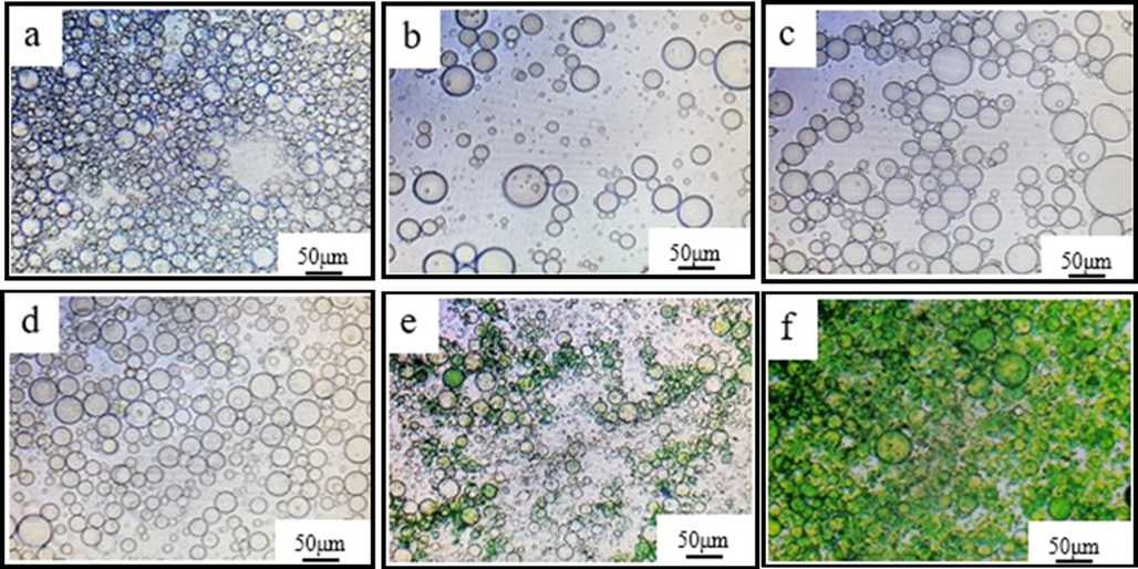
Monitoring PANI microcapsule formation by Optical Microscopy (OM) a-emulsification for 45 min, b-with addition of 10% acidified aniline, c-with addition of 10% APS for 1 h, d-after 30 min of residual aniline addition, e-after residual APS addition, f-completed reaction.
3.2 Experimental factors influencing the yield and characteristics of synthesized microcapsules
To explore the optimal synthesis process of PANI microcapsules, we studied the related influencing factors, such as stirring rate, oxidant APS dosage, and oxidation polymerization time. The synthesized microcapsules under different conditions were diluted to 1:3 with deionized water and then observed under OM. After observation, the sample was poured into a plastic bottle, and SEM was conducted for characterization.
3.2.1 Effect of stirring rate on the synthesis of microcapsules
On the basis of previous exploration experiments, different stirring rates during microcapsule polymerization, such as 200, 400, 500, 600, and 700 r/min, were analyzed in this paper. Fig. 3 shows the morphology of the microcapsules at different stirring rates. The stirring rate could produce different shear strengths and may affect the particle size of latex and amount of microcapsules during synthesis. When the stirring rate was low, such as 200 and 400 r/min, the particle size of the emulsified capsule core (acrylic resin) was large, and the formation of form stable emulsion droplets and complete spherical shell was difficult to achieve (Fig. 3A and 3B). Therefore, few complete microcapsules were formed (Fig. 3a and 3b). When the stirring rate was 500 r/min, the microcapsules with a regular spherical shape formed, but the particle size was not uniform (Fig. 3C). A few microcapsules were observed during SEM (Fig. 3c). When the stirring rate increased to 600 r/min, more microcapsules formed compared with that under other stirring rates (Fig. 3d). When the stirring rate was 700 r/min, the particle size of the microcapsules was small (Fig. 3E), but the number of polymerized microcapsules did not increase. Therefore, 600 r/min was chosen during synthesis.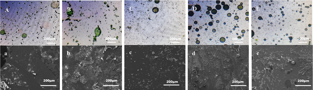
OM (top) and SEM (bottom) of synthesized microcapsules at different stirring rates A,a-200r/min; B,b-400r/min; C,c-500r/min; D,d-600r/min; E,e-700r/min.
3.2.2 Effect of oxidant dosage on the synthesis of microcapsules
OM and SEM images of microcapsules under different Ammonium persulfate (APS) oxidant dosages (3, 5, 7, 10, and 60 g) are shown in Fig. 4. Figure shows that when amount of the added oxidant APS increased so is the polymerization rate of aniline. When the added amount of APS was only 3 g, the polymerization of PANI on the emulsion surface was slow (Fig. 4A). When the addition amount of APS increased to 5 g, more microcapsules were observed (Fig. 4B and 4b). The amount of oxidant gradually increased to 7, 10, and 60 g. Aggregates of PANI with clusters increased, which indicated that PANI was not deposited on the surface of the emulsion as shell structure but polymerized directly in the solution (Fig. 4c-4e). The surface of the microcapsules was not dense and continuous, but it was formed by the accumulation of PANI aggregates. The SEM results showed that the oxidant amounts of 3, 7, and 10 g led to poor synthesis effects and low cladding rates. Thus, the optimum addition amount of the oxidant was 5 g.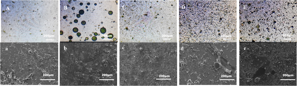
Comparison of OM and SEM under different oxidant dosages. A,a-3 g B,b-5 g C,c-7 g D,d-10 g E,e-60 g.
3.2.3 Effect of oxidation polymerization time on the synthesis of microcapsules
The different oxidation polymerization time was also discussed by controlling the addition time of the oxidant of APS in microcapsule synthesis. The addition time were 1, 3, 4, 5, and 7 h. The micropump was used to control the dropping quantity of APS. The oxidation polymerization times of 1 and 3 h, were insufficient to deposit aniline on the membrane layer on the surface of resin microspheres and led to its rapid polymerization. With the rapid increase in the oxidant dosage in the system, the polymerization rate of aniline increased, which aggravated the agglomeration of PANI. Therefore, a dense shell structure was hard to form, which resulted in a few synthesized microcapsules (Figurse 5a and 5b). When the oxidation polymerization time increased to 5 or 7 h, the oxidant concentration in the solution was the low due to slow feeding speed. The deposition rate of PANI decreased, and the time for forming a thick continuous capsule shell increased (Fig. 5d and 5e, respectively). The stability of the capsule shell structure decreased under stirring conditions. The oxidation polymerization time of 4 h was sufficient to deposit on the membrane layer on the surface of resin microspheres and form a continuous capsule shell. Fig. 5c also shows that microcapsule had a smooth shell. These results showed that 4 h was the optimum oxidation polymerization time.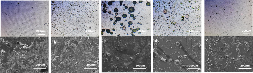
Comparison of OM and SEM under different oxidation polymerization times. A,a-1 h B,b-3 h C,c-4 h D,d-5 h E,e-7 h.
3.3 Characterization of PANI microcapsules
Microcapsules were successfully synthesized through the synthesis process studied above. The optimum process parameters for the synthesis of polyaniline microcapsules are as follows: the stirring rate was 600 r/min, addition amount of oxidant was 5 g, oxidation polymerization time is 4 h. Fig. 6 shows the SEM micrographs of the synthesized microcapsules under optimal conditions. As shown in Fig. 6a, the overall surface morphology of microcapsules was compact and tight, and no shrinkage phenomenon occurred, which indicates that the capsule shell had good coating performance and good stability. The number of microcapsules was high, and the morphology was spherical. The cracked microcapsule in Fig. 6b indicated that the thickness of the capsule shell was about 4 μm.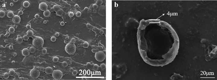
Microcapsule SEM images (optimal conditions: stirring rate was 600 r/min, addition amount of oxidant was 5 g, oxidation polymerization time is 4 h).
Fig. 7 displays the FT-IR results of acrylic resin, PANI, and microcapsules. For acrylic resin, the absorption peaks at 1730 and 3266 cm−1 were the characteristic peaks of C = O and –OH (Hassan et al., 2014); respectively. The band at 2953 cm−1 was assigned to the CH3 stretching vibration. PANI spectrum showed the absorption peaks at 1020–1360, 1470, and 1587 cm−1, which were the characteristic peaks of aromatic amine C-N, quinone structure N-B-N, and benzene structure N = Q = N (Parsa and Ghani, 2009; Ajeel and Kareem, 2019), respectively. Simultaneously, the distinct peaks of C = O, CH3, and –OH in acrylic resin and aromatic amine C-N, quinone structure N-B-N, and benzene structure N = Q = N in PANI could be observed on the spectrum of the microcapsule. But there was no change of the characteristic peaks. Thus, PANI and acrylic resin coexisted in the microcapsule, which indicates the successful synthesis the PANI-coated acrylic resin microcapsule.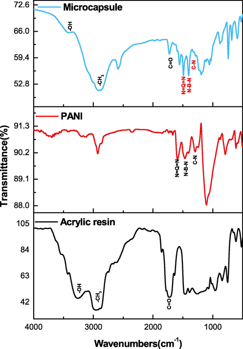
FT-IR of composite microcapsules, PANI and acrylic resin.
TGA of acrylic resin, PANI, and microcapsules are shown in Fig. 8. Weight loss of acrylic resin occurred before 100 °C because of the solvent, which was introduced during synthesis. The weight of acrylic resin decreased sharply at about 150 °C, indicating that this temperature was the thermal decomposition temperature of acrylic resin. When the temperature reached 700 °C, the total weight of acrylic resin approached zero. PANI began to lose weight after 100 °C and presented a gradient in the thermal decomposition curve. The weight of the sample remained about 40% after 800 °C. The weight loss curve of the microcapsule had a similar variation trend as that of acrylic resin before 150 °C presumably attributed to the loss of acrylic resin caused by pyrolysis. The second stage of weight loss of microcapsules was attributed to the simultaneous pyrolysis of acrylic resin and PANI. The residues of microcapsules were about 30% after 800 °C.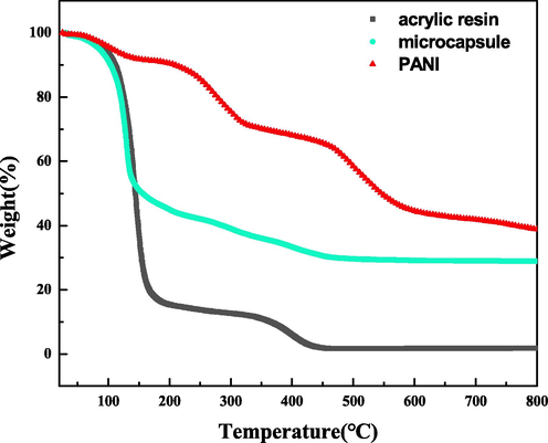
TGA of acrylic resin, PANI, and the microcapsule composite.
3.4 Effect of microcapsules on the protective performance of defect coating
Fig. 9 illustrates the EIS results of EP coating and 2% microcapsule coating with scratch immersed in 3.5 wt% NaCl solution for different times. After 4 h of immersion for the EP coating, two capacitive arcs in the Nyquist plot and two-time constants in the Bode diagrams were observed (Fig. 9a and 9b). The solution could penetrate into the magnesium alloy surface due to the existence of defects. Low-frequency impedance of defective EP coating was 1.1 × 10⁷ Ω·cm2. With the increase in the immersion time, the solution rapidly penetrated the coating to destroy the protective performance and the impedance value gradually decreased. One inductance arc became evident after 144 h of immersion (Fig. 9a, inset), which was attributed to the adsorbed intermediates during the corrosion of magnesium alloy and suggested occurrence of serious corrosion (Jamesh et al., 2011; Shao et al., 2009; Song et al., 1997). Under immersion for 336 h, the EP coating had lost protective capability for magnesium alloy, and low-frequency impedance reduced to 1.3 × 10⁴ Ω·cm2.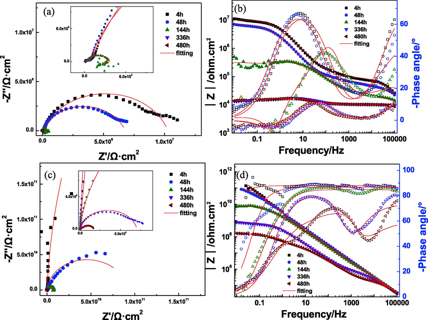
Impedance diagram of two kinds of coatings immersed in 3.5% NaCl solution. a) Nyquist plot of EP coating; b) Bode plot of EP coating; c) Nyquist plot of 2% microcapsule coating; d) Bode plot of 2% microcapsule coating.
The impedance value of 2% microcapsule coating with defect showed different characteristics from the EP coating under 480 h of immersion. During the initial immersion, the microcapsule coating showed one arc in the Nyquist plot and a high impedance value (Fig. 9c and 9d), which indicated that the coating had better shielding capability to the solution. When the microcapsule coating was destroyed, the capsule-core acrylic resin could flow out and be cured in a short time, thereby repairing the minor defect of the coating. For 144 h, the impedance value of the 2% microcapsule coating decreased to 7.1 × 10⁹ Ω·cm2, and two capacitive arcs were observed (Fig. 9c, inset). This result indicated that NaCl solution had reached the interface between the coating and magnesium alloy, but the corrosion reaction was mild because of high impedance values. As the immersion time increased continuously, the impedance values slowed down.
The equivalent circuit diagrams in Fig. 10 were employed to fit the EIS data, and the fitting results are shown in Fig. 9 with a solid red line. Based on the characteristics of the EIS of the EP coating, Model A (two time constants) was used prior to first before 144 h of immersion, and Model B was used because of the inductance arc. The 2% microcapsule coating had one capacitive arc. Thus, Model C was used at the beginning of immersion. Model A was also selected when two capacitive arcs were observed. For all equivalent circuits, Rs represents electrolyte resistance, and Qc and Rcoating denote the coating capacitance and coating resistance, respectively. Qdl and Rt indicate the double-layer capacitance and charge transfer resistance of the coating-metal interface, respectively. L and RL are the inductance and inductive resistance, respectively.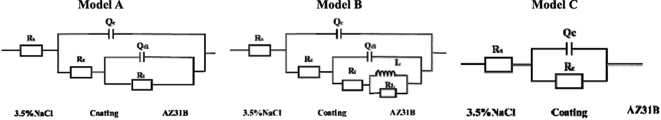
Equivalent circuit model.
Fig. 11 shows the trend with time of coating resistance Rcoating of the EP and 2% microcapsule coatings. The low Rcoating of EP at the beginning of immersion, 9.4 × 10⁴ Ω·cm2, was attributed to the artificial defect. The trend of Rcoating of EP showed a small decrease with time, which was related to the increase in the wet area under the coating. Random variations in Rcoating with the immersion time resulted in the formation of some corrosion products on the metallic surface. The 2% microcapsule coating had a very high value of Rcoating at 2.3 × 10¹² Ω·cm2 under 4 h of immersion. This value dropped gradually as the immersion time increased, but it was higher than that of the EP coating during the whole process. Microcapsule rupture and core acrylic resin flowed to the defect and were cured when the microcapsule coating suffered from damage. Therefore, the defect was repaired in a timely manner, the shielding performance of the coating was enhanced, and the reduced corrosive liquid entered the coating at the beginning of immersion. However, continuously penetrated corrosive medium caused the value of Rcoating to gradually decrease with the increase in immersion time.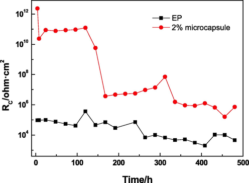
Rcoating versus different times.
Fig. 12 shows the variation curve of charge transfer resistance Rt with time of the EP and 2% microcapsule coatings. The Rt of the coating added with microcapsules was considerably higher than that of the EP coating during the whole process. The Rt of the EP coating remained unchanged before 96 h of immersion, reduced slowly until 336 h of immersion, and maintained stability until the end of immersion. The Rt of the EP coating was 3.9 × 10³ Ω·cm2 after 480 h of immersion. The macrophotograph of the EP coating showed extensive white corrosion around the defect and some corrosion away from the defect after 1000 h immersion (Fig. 13a). Before 144 h, the lack of Rt indicated that the corrosive medium had not fully reached the substrate and the magnesium alloy was protected via the barrier properties of the 2% microcapsule coating. Thereafter, the Rt was 2.7 × 10⁹ Ω·cm2, and it maintained steady levels until 312 h of immersion. The Rt of the 2% microcapsule coating decreased gradually until 480 h of immersion (1.6 × 10⁸ Ω·cm2). The high value of Rt indicated that the magnesium alloy beneath the microcapsule coating experienced difficulty with the occurrence of the corrosion reaction and low corrosion rate. The 2% microcapsule coating had some corrosion around the defect, and the other areas maintained their metal luster (Fig. 13b). According to previous research, PANI in coatings can inhibit the corrosion of magnesium alloy due to the formation of a protective film. The microcapsule shell was PANI, which had corrosion inhibition effect. Therefore, the 2% microcapsule coating had a corrosion inhibition effect on magnesium alloy, regardless of any position. Around the defect, penetrative corrosive medium led to some corrosion in spite of the corrosion inhibition function of PANI. In other areas, the PANI capsule shell inhibited corrosion but did not rupture.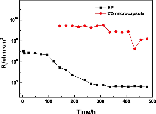
Rt versus different times.
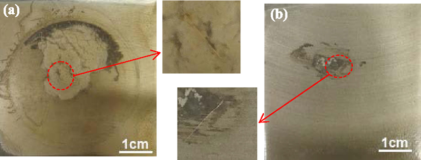
Surface morphologies of EP (a) and microcapsule (b) coatings after 1000 h immersion.
3.5 Corrosion protection mechanism of microcapsule coating
Fig. 14 shows the protection mechanism of microcapsules coating. The self-healing effect of the PANI microcapsule coating on magnesium alloy substrate is reflected in two aspects. First, the capsule shell PANI could exert a corrosion inhibition effect on magnesium alloy at any time, regardless of whether the microcapsules were broken. Second, after the microcapsules were broken, acrylic resin flowed out and solidified, and defects were rapidly repaired to restore the shielding performance of the coating. Thus, when the coating has tiny defects such as micropore defects, PANI plays the roles of corrosion inhibition and self-healing. When the coating received large defects such as damage, PANI on the shell of the capsule quickly played a role of corrosion inhibition and repair. By contrast, acrylic resin on the core of the capsule quickly solidified, repaired the shielding effect and improved the protective performance of the coating by double coordinated repair.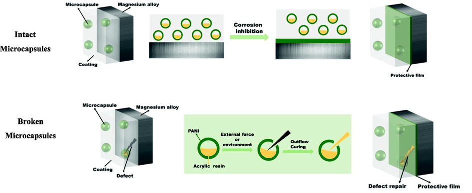
Schematic of protection mechanism of the microcapsule coating.
4 Conclusions
PANI microcapsules containing acrylic resin were successfully synthesized by emulsion polymerization under optimal producing conditions, and analyzed by SEM, FTIR, and TGA. The microcapsules were added in epoxy resin, and the coating was prepared on the surface of the AZ91D magnesium alloy. The EIS test results indicated that the microcapsule coating had better corrosion protection for magnesium alloy after 480 h of immersion in spite of its defect. PANI as a capsule shell played a role in corrosion inhibition and repair, and acrylic acid as a capsule core solidified and repaired the shielding effect of the coating. The addition of PANI microcapsules to epoxy coating is a promising technique for corrosion protection of metals. However, there are still many details to consider, for example, the corrosion protection of microcapsule coating could be affected by additive amount and particle size of microcapsules.
CRediT authorship contribution statement
Yingjun Zhang: Conceptualization, Writing – original draft, Supervision. Mengyang Li: Resources, Investigation. Jie Wen: Methodology. Xinyu Liu: Resources. Baojie Dou: Data curation. Yong Jiang: Resources.
Acknowledgements
The authors would like to acknowledge financial supports from the National Natural Science Foundation of China (No. U21A2045 and No.51801131), Sichuan Science and Technology Program (No.2022NSFSC0300 and No.2022ZHCG0076).
Declaration of Competing Interest
The authors declare the following financial interests/personal relationships which may be considered as potential competing interests: Yingjun Zhang reports financial support was provided by National Natural Science Foundation of China. Yingjun Zhang reports financial support was provided by Sichuan Science and Technology Program. Yingjun Zhang has patent licensed to Sichuan University of Science and Engineering.
References
- Lac-extract doped polyaniline nano-ribbons as fluorescence sensor and molecular switch for detection of aqueous AsO43− and Fe3+ contaminants. J. Photoch. Photobio. A.. 2022;431:114000
- [CrossRef] [Google Scholar]
- Synthesis and characteristics of polyaniline (PANI) filled by graphene (PANI/GR) nano-films. J. Phys. Conf. Ser.. 2019;1234:012020
- [CrossRef] [Google Scholar]
- Simplified in-situ tailoring of cross-linked self-doped sulfonated polyaniline (S-PANI) membranes for nanofiltration applications. J. Membrane Sci.. 2021;637:119654
- [CrossRef] [Google Scholar]
- Sodium silicate/polyurethane microcapsules used for self-healing in cementitious materials: Monomer optimization, characterization, and fracture behavior. Constr. Build. Mater.. 2018;162:57-64.
- [CrossRef] [Google Scholar]
- Urea-formaldehyde microcapsules containing an epoxy resin: influence of reaction parameters on the encapsulation yield. Macromol. Symp.. 2006;234:184-192.
- [CrossRef] [Google Scholar]
- Smart releasing behavior of a chemical self-healing microcapsule in the stimulated concrete pore solution. Cem. Concr. Compos.. 2015;56:46-50.
- [CrossRef] [Google Scholar]
- Selfhealing features in cementitious material with urea-formaldehyde/epoxy microcapsules. Constr. Build. Mater.. 2016;106:608-617.
- [CrossRef] [Google Scholar]
- Anti-corrosion and self-healing coatings with polyaniline/epoxy copolymer-urea-formaldehyde microcapsules for rusty steel sheets. J. Colloid. Interface Sci.. 2022;616:605-617.
- [CrossRef] [Google Scholar]
- Study the FTIR of hydroxyapatite additive to heat cured acrylic resin. Al-Rafidain Dent. J.. 2014;14:32-36.
- [Google Scholar]
- Corrosion behavior of commercially pure Mg and ZM21 Mg alloy in Ringer’s solution-Long term evaluation by EIS. Corros. Sci.. 2011;53:645-654.
- [CrossRef] [Google Scholar]
- Synthesis and characterization of poly(urea-formaldehyde) microcapsules containing linseed oil for self-healing coating development. Prog. Org. Coatings.. 2017;105:99-110.
- [CrossRef] [Google Scholar]
- Smart coating based on double stimuli-responsive microcapsules containing linseed oil and benzotriazole for active corrosion protection. Corros. Sci. 2017
- [CrossRef] [Google Scholar]
- Preparation and application of polysulfone microcapsules containing tung oil in self-healing and self-lubricating epoxy coating. Colloids Surf. A Physicochem. Eng. Asp.. 2017;518:181-187.
- [CrossRef] [Google Scholar]
- Preparation and properties of melamine ureaformaldehyde microcapsules for self-healing of cementitious materials. Mater.. 2016;9(3):152.
- [CrossRef] [Google Scholar]
- Preparation of a novel IPDI/PUF@CeO2 bi-functional microcapsules and its improvement for the self-healing and anti-corrosion performance in epoxy coatings. Prog. Org. Coat.. 2022;169:106897
- [CrossRef] [Google Scholar]
- Trigger efficiency enhancement of polymeric microcapsules for self-healing cementitious materials. Constr. Build. Mater.. 2020;235:117443
- [CrossRef] [Google Scholar]
- Preparation of polyaniline (PANI)-coated Fe3O4 microsphere chainsand PANI chain-like hollow spheres without using surfactants. RSC Adv.. 2015;5:103064-103072.
- [CrossRef] [Google Scholar]
- Fabricating and tailoring polyaniline (PANI) nanofibers with high aspect ratio in a low-acid environment in a magnetic field. Chem. Asian J.. 2016;11:93-101.
- [CrossRef] [Google Scholar]
- Synthesis of PANI solid microspheres with convex-fold surface via using polyvinylpyrrolidone micellar template. Synthetic Met.. 2016;222:388-392.
- [CrossRef] [Google Scholar]
- The improvement of free-radical scavenging capacity of the phosphate medium electro synthesized polyaniline. Electrochim. Acta. 2009;54:2856-2860.
- [Google Scholar]
- Corrosion protective self-healing epoxy resin coatings based on inhibitor and polymeric healing agents encapsulated in organic and inorganic micro and nanocontainers. Nano-Struct. Nano-Obj.. 2018;16:381-395.
- [CrossRef] [Google Scholar]
- Corrosion protection of Mg–5Li alloy with epoxy coatings containing polyaniline. Corros. Sci.. 2009;51:2906-2915.
- [CrossRef] [Google Scholar]
- Self healing coatings containing dual active agent loaded urea formaldehyde (UF) microcapsules. Prog. Org. Coat.. 2015;82:57-67.
- [CrossRef] [Google Scholar]
- The anodic dissolution of magnesium in chloride and sulphate solutions. Corros. Sci.. 1997;39:1981-2004.
- [CrossRef] [Google Scholar]
- Formation and comparison of polyaniline microfibers by bi-phase volume asymmetrical interfacial polymerization. Mater. Lett.. 2016;172:99-101.
- [CrossRef] [Google Scholar]
- Self-healing mechanisms of water triggered smart coating in seawater. J. Mater. Chem. A. 2014;2:1914-1921.
- [CrossRef] [Google Scholar]
- Development and performance of stable PANI/MWNT conductive membrane for contaminants degradation and anti-fouling behavior. Sep. Purif. Technol.. 2022;282:120112 Part B
- [CrossRef] [Google Scholar]
- Self-healing mechanisms in smart protective coatings: A review. Corros. Sci.. 2018;144:74-88.
- [CrossRef] [Google Scholar]
- The effect of epoxy coating containing emeraldine base and hydrofluoric acid doped polyaniline on the corrosion protection of AZ91D magnesium alloy. Corros. Sci.. 2011;53:3747-3755.
- [CrossRef] [Google Scholar]
- A study on corrosion protection of different polyaniline coatings for mild steel. Prog. Org. Coat.. 2017;111:240-247.
- [CrossRef] [Google Scholar]


