

Translate this page into:
Titania and zirconia ceramic nanofiltration membrane fabrication by coating method on mullite and mullite-alumina microfiltration supports for industrial wastewater treatment
⁎Corresponding authors at: Department of Chemical Engineering, Faculty of Petroleum, Gas and Petrochemical Engineering, Persian Gulf University, Bushehr 75169, Iran (A. Azari); Department of Engineering, University of Exeter, EX4 4QF, United Kingdom (M. Akrami). azari.ahmad@pgu.ac.ir (Ahmad Azari), m.akrami@exeter.ac.uk (Mohammad Akrami)
-
Received: ,
Accepted: ,
This article was originally published by Elsevier and was migrated to Scientific Scholar after the change of Publisher.
Abstract
Industrial wastewater treatment increasingly relies on membrane separation, with ceramic membranes offering many advantages such as thermal stability and pH resistance. The resistance of ceramic membranes to extreme pH conditions indicates their ability to maintain structure and performance when exposed to highly acidic or alkaline environments. A high-permeability ceramic nanofiltration membrane was developed, boasting excellent rejection rates through a multilayer asymmetric design. Initially, two tubular porous supports, mullite and mullite-alumina, with a weight percent of 50, were fabricated using the extrusion method. Subsequently, a colloidal sol of titania (TiO2) and titania-zirconia (TiO2- ZrO2) was prepared via the sol–gel method and coated on the ceramic supports using the dip-coating method. After analyzing the membrane microstructure using SEM, XRD, and BET, the efficiency of the membranes in treating synthetic oily wastewater was evaluated. The results underscore the significant impact of the Donnan exclusion mechanism on the rejection of nanofiltration (NF) membranes. An increase in pressure led to a rise in rejection rates up to 7 bars. The Chemical Oxygen Demand (COD) rejection for mullite-titania zirconia (MTZ) and mullite-alumina-titania zirconia (MATZ) membranes was 98.65 % and 98 %, respectively. The pure water permeability test results for mullite and mullite-alumina supports, as well as MTZ and MATZ membranes, were recorded as 254, 382, 70, and 89 L bar-1m-2h−1, respectively.
Keywords
Multilayer ceramic membrane
Mullite
Mullite-alumina
Nanofiltration
Titania-Zirconia
Sol-gel

1 Introduction
Industrial wastewater is one of the most significant sources of environmental pollutants. Over the last century, a large amount of industrial wastewater has been released into rivers, lakes, and ecosystems. This practice has caused serious pollution problems in environmental waters, leading to negative effects on the ecosystem, human health, and the economy (Ghanbarizadeh et al., 2022). The wastewater constituents join the underground water without any change, and under these conditions, the necessity of wastewater treatment doubles (Samer, 2015). After the purification process, the wastewater can be discharged into the environment or reused (Nicholas and Cheremisinoff, 2002). Membrane separation methods have been extensively developed and have become a promising technology among various industrial wastewater treatment methods. Membrane methods offer high removal efficiency, low energy costs, and compact designs compared to traditional methods (Dong et al., 2023; Wang et al., 2021). Membranes are made of different materials, each with its own characteristics. Two types of membranes, polymeric and ceramic, are used for wastewater treatment (Luck, 1984). Due to properties such as low energy consumption, mechanical resistance, thermal stability, and resistance to extreme pH conditions, ceramic membranes have a longer lifespan than the polymer type and are more economical in practice. Additionally, ceramic membranes have a much higher flow rate and can be sterilized by heating or steam flow, while polymer membranes do not benefit from this advantage (Mulder, 2012). Steam sterilization effectively removes biological contaminants like bacteria, viruses, and microorganisms, ensuring high water quality standards. It also helps maintain membrane efficiency by preventing biofouling and microbial growth, thereby prolonging the membrane's lifespan and reducing maintenance costs (Nastouli et al., 2022).
Porous ceramic membranes are mainly made in an asymmetric multilayer structure, which includes a holding layer (substrate), an intermediate layer, and a selective layer (Abbasi et al., 2010; Guo et al., 2016). The basis of ceramic membranes is a thick and porous substrate called the support, on which one or more thin layers are placed as an intermediate layer and a selective layer. The main methods of making the support in ceramic membranes include slurry casting, dry pressing, and extrusion (Campbell, 2010). To a large extent, membrane flux is controlled by support parameters, including thickness, pore size, and pore size distribution. Additionally, the wettability of the support affects the quality and efficiency of the membrane (Fan et al., 2016; Shqau et al., 2006). An important point that should be taken into account in the coating of ceramic supports is that the size of the particles in the coating layers should not be much smaller than the pores on the substrate surface; otherwise, the particles of the coating layer will easily pass through the pores of the substrate, resulting in coating defects. Membrane films can be prepared using different coating methods, which include dip-coating, spraying, and spin-coating methods (Burggraaf and Cot, 1996). One of the best coating methods for ceramic membranes is the dip-coating method (Alftessi et al., 2022). There are two different mechanisms involved, including capillary filtration of colloids and film coating, to form a layer on the support surface (Burggraaf, 1996).
By replacing expensive raw materials with cheap minerals, we can expect a significant reduction in ceramic membrane manufacturing costs (Harabi et al., 2014; Lorente-Ayza et al. 2015). Among porous mineral materials, mullite and mullite–alumina ceramic materials have advantages such as high thermal durability, a low expansion coefficient, high chemical stability, excellent mechanical properties, and low cost (Esharghawi et al., 2009; Abbasi et al., 2010). Mullite, composed of alumina and silica, is chemically inert and resistant to acidic and alkaline environments, making it stable over a wider pH range in comparison to alpha-alumina (α-Al2O3). Currently, various types of oxide materials, including alumina (Al2O3), TiO2, zirconia (ZrO2), and others, are employed in the development of ceramic NF membranes (Grib et al., 2000; Kuzniatsova et al., 2008; Schaep et al., 1999). Among them, TiO2 and ZrO2 materials have relatively high chemical resistance, and their photocatalyst properties cause the decomposition of organic materials, which has increased their use in ceramic membranes (Van Gestel et al., 2002; Qi et al., 2012; Puhlfürß et al., 2000). To achieve better performance, TiO2 and ZrO2 composite ceramic NF membranes have been proposed (Tsuru et al., 2001; Tsuru et al., 1998).
In recent studies, the development of nanofiltration membranes using nanoparticles has received significant attention. Chang et al. (2010) successfully coated the surface of a commercial Al2O3 membrane with Al2O3 nanoparticles, resulting in a γ-Al2O3 membrane with improved surface properties. The hydrophilicity and flux of the membrane were enhanced compared to its initial state, and it showed about 98 % oil rejection in a wastewater sample. Larger oil droplets may face challenges in passing through smaller pores in membranes, leading to enhanced oil retention. Conversely, smaller droplets could potentially pass through more easily, impacting retention differently. Membranes with varying pore sizes and structures may interact uniquely with oil droplets of different sizes, affecting retention mechanisms (Yushkin et al., 2023; Yan et al., 2022). Nandi et al. (2010) achieved the production of a cost-effective ceramic membrane using materials such as kaolin, quartz, feldspar, sodium carbonate, and sodium metasilicate. Tests on two samples of artificial wastewater containing oil showed COD rejection of 93 % to 98 % at different pressures. Habibpanah et al. (2011) prepared a combined membrane of TiO2 and Al2O3 using two different sol–gel methods. The membranes were characterized by Brunauer-Emmett-Teller (BET) tests. The combination of Al2O3 and TiO2 increased the specific surface area while also reducing the membrane's pore size. Hong et al. (2011) investigated the separation of chloride ions using a TiO2-Al2O3 two-layer nanofiltration membrane. They prepared a two-layer membrane based on α-Al2O3 support and studied its efficiency for chlorine removal using vertical flow and cross-flow membrane filtration devices at laboratory temperature. The results indicated that the amount of chlorine excretion decreased with increasing concentrations of sodium chloride solution. Rising pressure led to an increase in the amount of chlorine excretion. Guo et al. (2018) prepared ceramic nanofiltration membranes from TiO2-ZrO2 using the polymer sol–gel process. The membrane's support was made of α-Al2O3 and covered with gamma Al2O3 as the middle layer. Their constructed membranes had a pore size between 1.2 and 1.5 nm and low permeability due to the very low porosity of the main layer (1.9–2.4 %). Puthai et al. (2017) utilized the colloidal sol–gel process and dip-coating to make nanofiltration membranes with a low molecular weight cut-off. Their porous support was made of α-Al2O3 and tubular in shape, with the outer surface covered with different molar ratios of SiO2-ZrO2. The rejection rate for alcohols was much higher than for glycols or sugars, and the SiO2-ZrO2 membranes exhibited high hydrothermal stability and nanofiltration performance. Anisah et al. (2018) synthesized a TiO2-ZrO2 composite membrane on a tubular substrate made of α-Al2O3 using the colloidal sol–gel process and a dip-coating method. They investigated the performance of nanofiltration with changes in sintering temperature, and the water permeability of the membranes improved with increasing sintering temperature. Dong et al. (2019) synthesized polymer-derived porous SiOC ceramic membranes for efficient oil–water separation. The results showed a COD rejection of 95 %. Lee et al. (2022) evaluated the structural and functional changes between α-Al2O3 and polyvinylidene fluoride (PVDF) membranes for use in long-term clean-in-place water treatment. The α-Al2O3 membrane displayed less susceptibility to membrane fouling and less structural degradation than the PVDF membrane, with 12 % less residual fouling and high and stable rejection efficiency. Mao et al. (2023) presented a piezoceramic membrane equipped with a super-wet interface for efficient separation of oil–water emulsions. SiO2-Al2O3-MgO was applied to quartz-based ceramics to obtain a porous support. Due to the low adhesion between the oil droplets and the super-wet membrane, its permeability increased by 25.3 %, while the rejection remained above 99.7 %. A novel technique for combining low-temperature co-sintering and spraying was presented by Jiang et al. (2024) in order to create asymmetric water glass-bonded SiC microfiltration membranes for oil–water separation while lowering production costs. High oil rejection was observed in the data (98.9 %).
Currently, various types of oxide materials are employed in the development of ceramic NF membranes. Among them, TiO2 and ZrO2 materials have relatively high chemical resistance, and their photocatalyst properties cause the decomposition of organic materials, which has led to their increased use in ceramic membranes.
According to recent studies, the application of nanofiltration ceramic membranes for industrial wastewater treatment is becoming increasingly popular. However, most of the ceramic supports that have been made so far have been flat and made of Al2O3. There has been no exploration of using mullite and mullite-alumina substrates for TiO2 and ZrO2 coatings. Therefore, the novelty of this research lies in investigating the fabrication of tubular mullite and mullite-alumina supports, emphasizing their properties and characteristics to achieve a suitable support for the TiO2 and ZrO2 nanofiltration membrane. This study offers insights into the performance of these membranes in treating oily wastewater by providing a detailed investigation into the fabrication process, membrane characterization, and rejection efficiency. The process involves creating substrates made of mullite and mullite-alumina (50 %) and then coating them using a sol of TiO2 and TiO2-ZrO2 nanoparticles through the dip-coating method. In the subsequent steps of this study, the pore size distribution, permeate flux, membrane morphology, and their performance in treating synthetic oily wastewater were examined to evaluate the effectiveness and suitability of the developed ceramic membranes (Table 1).
SiO2 (wt%)
TiO2 (wt%)
Al2O3 (wt%)
Fe2O3 (wt%)
K2O (wt%)
Na2O (wt%)
L.O.I (wt%)
61.62
0.40
24–25
0.45–0.65
0.40
0.50
9.5–10
2 Materials and methods
2.1 Materials
Kaolin powder was purchased from China Clay Industries Company, Iran. α-Al2O3 powder with a purity of 99.6 % and a particle size of 50 µm was obtained from Semnan Mines, Iran, for making ceramic supports. The titanium butoxide precursor Ti(OBu)4 with 97 % purity was purchased from Aldrich. A zirconium oxynitrate hydrate precursor with a purity of 99.5 % was provided by Merck. Isopropanol with a purity of 99.8 %, manufactured by Merck, was used as a solvent to prepare stable TiO2 sol. Nitric acid (HNO3) with a purity of 65 % and sodium hydroxide with a purity of 99.5 % were purchased from Merck. Polyvinyl alcohol (PVA) with a molecular weight of 72,000, manufactured by Merck, was applied to prepare TiO2 and TiO2- ZrO2 sols. The chemical formula of PVA is (C2H4O)x. Glycerol, made by Merck with 100 % purity, was used to reduce the size of colloidal sol particles. Hydroxypropyl methyl cellulose (HPMC) with a molecular weight of 100,000, manufactured by Oxin Chemistry Toos, Iran, was used to improve the performance of the sintering process. Diethanolamine (DEA) with 99 % purity, manufactured by Merck, was employed as a reaction rate controller in the sol–gel process. Triton X-100 (C14H22O(C2H4O)n) with a purity of 99 % was purchased from Merck. Distilled water was used in the experiments. For the synthetic wastewater, crude oil from Gachsaran, Iran, was used, and the physical properties and chemical composition of the crude oil are shown in Table 2.
Sulfur (wt%)
nitrogen (wt%)
Asphaltene (wt%)
Wax (wt%)
Ash (wt%)
Nickel (mg L-1)
Vanadium (mg L-1)
Iron (mg L-1)
Lead (mg L-1)
Sodium (mg L-1)
1.62
0.21
3.6
6.06
0.025
29
105
2.6
<1
10
2.2 Fabrication of mullite and mullite-alumina 50 % ceramic supports
In this study, two types of mullite and mullite-alumina 50 % ceramic supports were prepared using the same extrusion and thermal sintering methods. To make the mullite ceramic support, 23 wt% of distilled water was added to 77 wt% of kaolin soil until a uniform dough was formed. Similarly, to make the 50 % mullite-alumina ceramic support, 23 wt% of distilled water was added to 77 wt% of soil containing 50 % kaolin and 50 % α-Al2O3 until a homogeneous paste was obtained. The two doughs were then separately poured into the extruder chamber and shaped to form tubular supports. Finally, supports with an inner diameter of 10 mm, an outer diameter of 14 mm, and a length of 25 cm were cut from the shaped dough. Subsequently, the supports were dried for two days at ambient temperature and subjected to calcination and thermal sintering using an electric furnace. Fig. 1 illustrates the heating schematic of the ceramic supports with different temperature gradients. The distinct calcination processes may indeed influence the morphology and characteristics of the ceramic particles. Scanning electron microscope (SEM) and X-ray diffraction (XRD) analyses can be used to examine and compare the structural properties of the supports and the coating layers.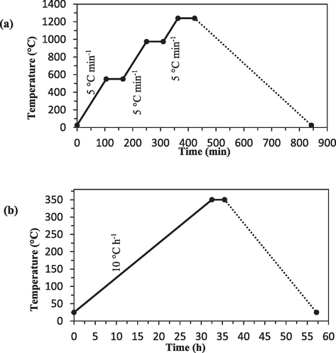
Schematic of heating in calcination operation (a) ceramic supports (b) Selective layer.
The calcination operation takes place during a precise and planned process with different temperature gradients. The calcination of ceramic supports is done in such a way that the membranes are heated at a rate of 5 °C/min from ambient temperature to 550 °C. Then the heating operation continues at 550 °C for 1 h. At this temperature, an endothermic reaction takes place, which is related to the formation of meta-kaolin from the kaolinite phase. Again, the membranes are heated with a gradient of 5 °C/min up to a temperature of 975 °C. The sintering of supports continues for 1 h at 975 °C. With further heating, the mullite and free silica phase are formed at around 1050 °C.
2.3 Preparation of TiO2 sol by colloidal sol–gel method
In this research, glycerol was used as an organic additive with properties that improve the structure of TiO2 nanoparticles. Literature has demonstrated that glycerol, when utilized as a solvent or dispersant, can impact the size of particles due to its capacity to alter the surface characteristics of particles and regulate their interplay. These interactions between glycerol and colloidal particles can lead to a reduction in particle size during the fabrication process (Vasylyshyn et al., 2023). The effect of adding glycerol before the coagulation stage was investigated. For preparing TiO2 colloidal sol, a certain amount of Ti(OBu)4 and isopropanol were mixed on a magnetic stirrer for 30 min. Then, a specific amount of DEA was combined with the mixture and stirred for another 30 min. Subsequently, the mixture was added dropwise to distilled water at a temperature of 50 °C, and the stirring continued for one hour. Afterward, glycerol was added and thoroughly mixed. In the final step, a specific amount of 1 M HNO3 solution was added to the mixture for peptization, and the stirring operation continued for 6 h at a temperature of 50 °C to obtain the TiO2 colloidal sol.
Adding glycerol before the peptization step significantly reduced the required acid consumption. The molar ratio of materials, including Ti(OBu)4, DEA, HNO3, and water, was equal to 1, 0.8, 2.4, and 1000, respectively.
To synthesize TiO2 powder, a portion of the TiO2 colloidal sol was poured into a crucible and kept at laboratory temperature for 24 h. Subsequently, it was dried in an oven at 60 °C for 12 h. Afterward, it was transferred to an electric furnace. The calcination process was performed at 350 ℃ for 3 h. The rate of increase and decrease of the furnace temperature was set at 0.5° C/min. The resulting calcined TiO2 powder was then used for XRD and BET tests to characterize the membrane layers.
2.4 Preparation of TiO2- ZrO2 20 % sol by colloidal sol–gel method
To prepare the TiO2-ZrO2 sol with a molar ratio of 80 to 20, the following steps were performed: First, solutions of 0.45 M Ti(OBu)4 in isopropanol and 4.5 M water in isopropanol were prepared and stirred for 30 min (22.2 mol of H2O were used per mole of Ti(OBu)4). Both solutions were mixed by adding the first solution dropwise to the second solution. After the completion of the reaction, the precipitates were filtered and washed with water. The product was then diluted to a concentration of 0.2 M and refluxed at 80 °C for 2 h. For each mole of titanium alkoxide, 10 mol of glycerol were added dropwise to the solution and stirred for 1 h. The solution was adjusted to a pH of about 2 using 0.1 M HNO3 and then refluxed at a temperature of 80 °C for 24 h. The product was placed in an ultrasonic water bath for 1 h.
To prepare the ZrO2 sol, a certain amount of zirconium oxynitrate hydrate was dissolved in distilled water and stirred for 1 h on a magnetic stirrer. Then, the ZrO2 sol was mixed with the TiO2 sol on reflux and stirred for another hour (the molar ratio of ZrO2 to TiO2 was equal to 0.2). The final concentration of the metal in the solution was determined to be 0.2 M. A solution of 0.1 g of PVA in 100 cc of distilled water and a solution of 0.35 g of HPMC in 100 cc of distilled water were prepared. After adding these two solutions to the TiO2-ZrO2 sol, the reflux operation continued for 1 h at 50 °C. Finally, the product was placed in an ultrasonic water bath for one hour to obtain the final sol. HPMC can enhance the performance of the sintering process by improving the cohesion of the mixture, leading to better formability and reduced cracking during sintering. For the preparation of TiO2-ZrO2 powder, the same method employed for TiO2 powder was used.
2.5 Coating of TiO2 and TiO2-ZrO220% sols by dip-coating method on mullite and mullite-alumina supports
The coating process was performed using the dip-coating method with TiO2 sol as the intermediate layer and TiO2-ZrO2 20 % as the selective layer. A schematic of this stage is shown in Fig. 2(a). The desired sol (either TiO2 or TiO2-ZrO2) from tank (1) flowed through the silicone hose into the ceramic membrane when valve (3) was opened. The sol covered the inner surface of the tubes, forming a thin layer due to capillary force upon contact with the inner surface. For the TiO2 sol, the coating time ranged from 5 to 10 min, while for the TiO2- ZrO2 sol, it was between 5 and 10 s.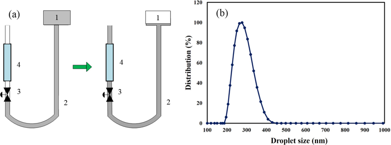
(a) Schematic of sol TiO2 and TiO2-ZrO2 20% by dip-coating method on the inner surface of mullite and mullite-alumina supports (1) colloidal sol tank (2) silicone hose (3) two-way valve (4) tubular ceramic membrane, (b) Oil droplet size distribution in wastewater.
After coating, the coated supports were kept in a relatively humid environment for 24 h. Then, the samples were dried for 12 h in an oven at a temperature of 60 °C. Subsequently, the coated supports were placed in an electric furnace for calcination, as shown in Fig. 1(b). The supports were heated to a temperature of 350 ℃ with a heat rate of 10° C/h and kept at this temperature for 3 h, then cooled with a heat rate of 15° C/h. To increase the thickness of the TiO2 and TiO2-ZrO2 layers and cover possible cracks, all the steps of coating, drying, and calcination were repeated once more.
2.6 Preparation of synthetic oily wastewater
In the preparation of synthetic oily wastewater, crude oil and distilled water were mixed together. To form an emulsion, 0.01 wt% of Triton X-100 was added as an emulsifier. The mixture was then homogenized using a homogenizer (Wise Mix HG 15, Korea) at a speed of 20,000 rpm for 30 min (Jafari et al., 2020). The resulting synthetic oily wastewater had a COD of 1000 mg/L. The size of oil droplets in the water emulsion was in the range of 200 to 400 nm. The results of the DLS analysis detailing the size distribution of oil droplets in the synthetic wastewater are shown in Fig. 2(b).
2.7 Characterization
In the characterization process, an SEM was used to examine the morphology and cross-sectional area of the mullite and mullite-alumina supports, as well as the thickness of the coated layers on the supports. SEM images were recorded using a device (VEGA3, TESCAN, Czech Republic). To estimate the porosity of the constructed membranes, the water saturation method and equation (1) were used (Rasouli et al., 2017).
2.8 Membrane performance
To measure the pure water permeability, deionized water at ambient temperature was employed. Each of the mullite and mullite-alumina supports, as well as the coated supports, was placed inside the module with an effective surface area of 44 cm2. The permeability test was conducted at pressures ranging from 1 to 7 bar, and the flow mechanism in the membrane was cross-flow. The schematic of the designed membrane nanofiltration system is shown in Fig. 3. In the system, the wastewater solution or distilled water is directed to the needle valve by the pump. By opening and closing the valve, the flow rate can be adjusted, and some of it is returned to the tanks. The inlet pressure to the membrane can be adjusted using the valve installed at the end of the module. By gradually opening and closing it, the pressure and flow rate of the incoming flow to the membrane in the module can be controlled. The flux (J) of purified water by the membrane was measured using equation (3) (Arzani et al., 2018).
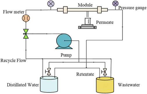
Schematic of the designed membrane nanofiltration system.
The amount of salt removal for salt solutions (NaCl, CaCl2, and MgCl2) was checked by measuring the ion concentration of the salt solution on both sides of the feed and permeated solution. For this purpose, solutions with a concentration between 0.1 and 0.01 mol/L were prepared, and the ion rejection percentage for the membranes was determined using equation (4). In this research, synthetic oily wastewater was applied to investigate the efficiency of ceramic NF membranes. The rejection percentage of the membrane for the synthetic oily wastewater was determined by measuring the COD of the wastewater (feed) and permeated flow. For this purpose, a COD reactor (DRB 200, HACH) was used after digesting samples at 150 °C for two hours. After cooling, the samples were placed in the spectrophotometer (DR3900, HACH), and the COD value was read using the COD LR430 program. The rejection percentage was calculated using equation (4):
3 Results and discussion
3.1 Membrane characterization
3.1.1 Membrane morphology and chemical composition
Fig. 4(a) and Fig. 4(b) show the SEM images of the surface of two types of mullite and mullite-alumina supports, respectively. From the images, it can be observed that the structures of both supports are different from each other. Both supports have porous and uneven surfaces, with the mullite-alumina support having more porosity than the mullite support. Additionally, the examination of the electron microscope images confirms that the surfaces of the supports are free of cracks. Fig. 4(c) displays the SEM images of the surface of the coated TiO2 membrane. It is evident that the TiO2 membrane surface has good homogeneity. Fig. 4(d) depicts the SEM images of the surface of the TiO2-ZrO2 membrane, which is formed on the TiO2 layer. Careful observation of Fig. 4(d) reveals that the surface of the microfiltration membrane coated by TiO2-ZrO2 nanoparticles also has good homogeneity, and its pores are significantly small. Finally, Fig. 4(e-g) shows the SEM images of the cross-sectional surface of the final membranes. In Fig. 4(g), the layers formed on the support can be seen, providing a visual representation of the membrane structure and composition.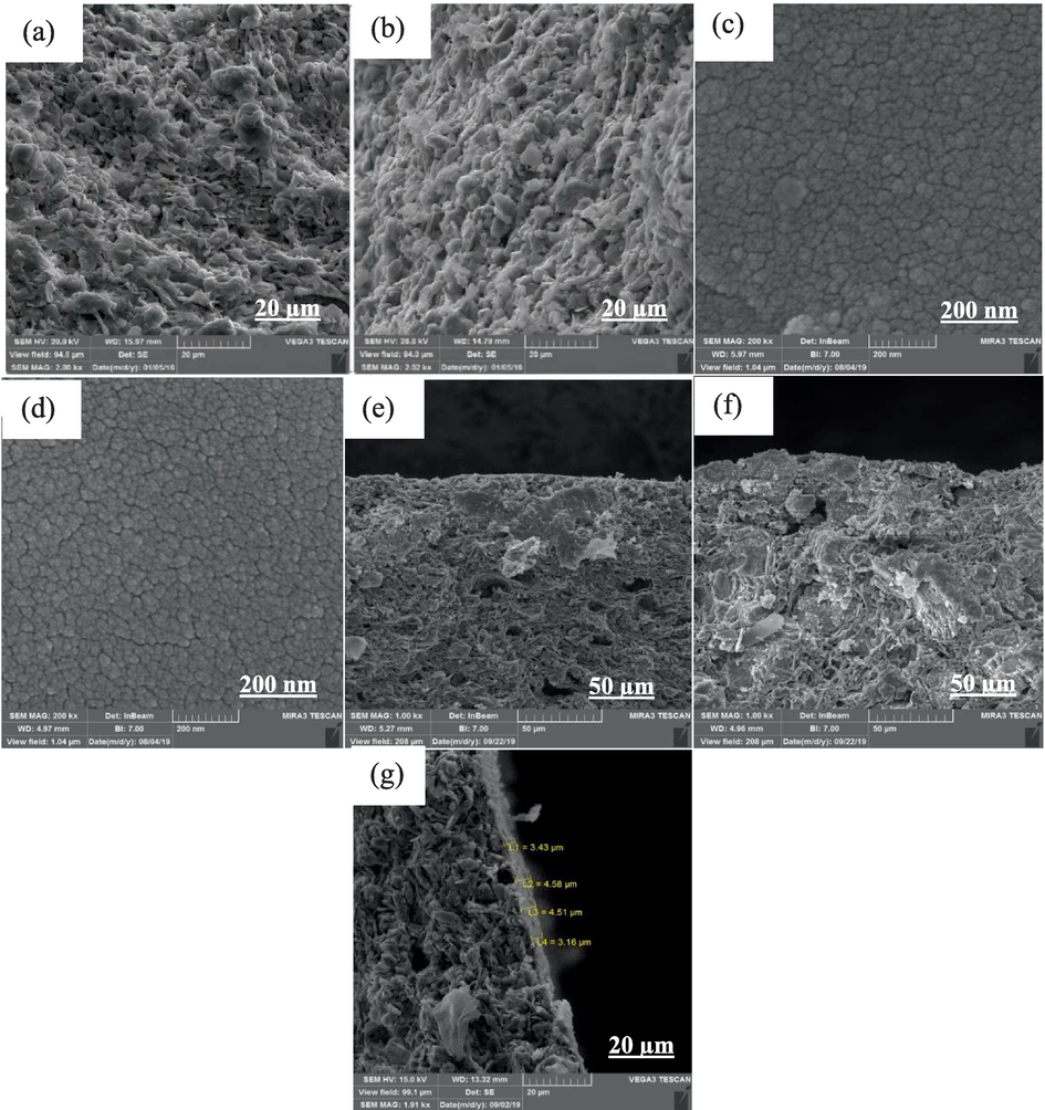
SEM images (a) mullite support, (b) mullite-alumina support, (c) top layer of TiO2 membrane, (d) top layer of TiO2- ZrO2 membrane, (e-f) cross-sectional area of MTZ and MATZ membranes with 1 kx magnification, (g) cross-sectional area of MTZ membrane with 1.91 kx magnification.
In order to identify the crystal phases of the layer formed on the supports, an XRD test was performed, and the results are presented in Fig. 5. In Fig. 5(a1), which represents the XRD pattern for the mullite support, the most formed phases are quartz and mullite, while the least formed phase is cristobalite. In Fig. 5(b1), which corresponds to the mullite-alumina support, the most formed phases are mullite, corundum, and quartz, while the least formed phase is cristobalite. Fig. 5(c1) shows the XRD diagram for the TiO2 layer, and according to the diagram, it is evident that the anatase phase is well formed. Fig. 5(a2,b2,c2) shows images of matching the created peaks (Fig. 5(a1,b1,c1)) with the standard peaks.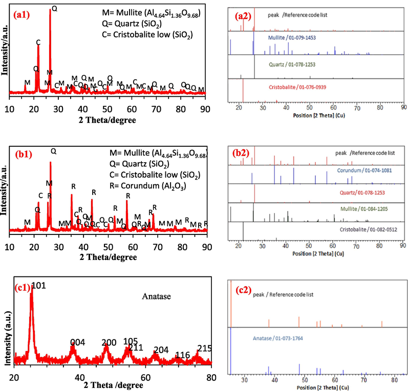
XRD diagram (a1) mullite support calcined at 1240 °C, (b1) mullite-alumina support calcined at 1240 °C, (c1) dried TiO2 powder calcined at 350 °C, (a2,b2,c2) Image of matching the created peaks with the standard peaks.
BET analysis is shown in Fig. 6 to determine the specific surface area of TiO2 and TiO2-ZrO2 samples. The adsorption and desorption isotherms of TiO2 and TiO2-ZrO2 20 % samples are depicted in Fig. 6(a), which includes hysteresis loops. Based on these loops, the specific surface area of the samples has been calculated. With the addition of ZrO2, the hysteresis loop changes from type H2 to type H4. The H2 hysteresis loop is characteristic of mesoporous materials composed of spherical particles and encompasses a relatively broad distribution of pore sizes. The change in the shape of the hysteresis loop indicates a variation in the size and shape of mesopores, leading to an increase in the number of micropores. Specifically, in materials exhibiting a type H4 hysteresis loop in their adsorption and desorption isotherms, their pores consist of mesopores and micropores. One of the key factors that can lead to the narrowing of the hysteresis loop is the increase in pore connectivity or the decrease in tortuosity. According to the diffusion theory, the greater the connectivity between network pores, the easier the filling of pores by vapor, resulting in a narrower hysteresis loop. High tortuosity of the network typically creates broader hysteresis loops, provided that significant interference from resistance effects against compression does not exist.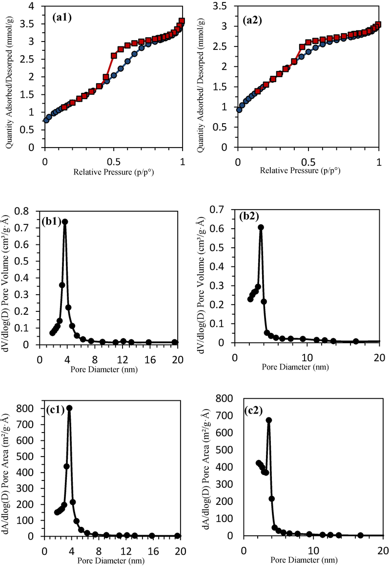
BET analysis (a) adsorption and desorption isotherms, (b) pore volume distribution, (c) pore area distribution, for (1) TiO2 powder, (2) TiO2- ZrO2 powder.
The results of quantitative nitrogen absorption data for TiO2 and TiO2-ZrO2 powders are given in Table 3. The mean pore volume of TiO2 and TiO2-ZrO2 20 % membranes is 0.1155 and 0.1016 cm3/g, respectively, and the mean pore size of TiO2 and TiO2-ZrO2 membranes is 3.9463 and 3.3947 nm, respectively. As illustrated in Fig. 6(b), adding 20 mol% ZrO2 to TiO2 has resulted in a narrower pore volume distribution curve. Furthermore, in Fig. 6(c), comparing the pore area distribution of TiO2 and TiO2-ZrO2 20 % reveals that the addition of ZrO2 to TiO2 has led to a narrower pore area distribution curve. The uniformity of the pore volume distribution and the pore area distribution have shown the success of the sol–gel method and the preparation of nanoparticles. Fig. 7(a) shows an example of ceramic supports after calcination. Two models have been proposed to describe the separation mechanism, as depicted in Fig. 7(b). The first model is the solution- diffusion model, while the second is the pore-flow model.
Sample
Mean pore volume (cm3 g−1)
Mean pore diameter (nm)
Specific surface area (m2/g)
TiO2
0.1155
3.9463
104.4211
TiO2- ZrO2
0.1016
3.3947
127.739
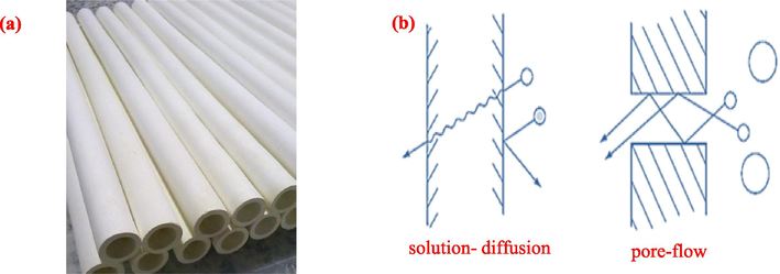
(a) Tubular porous supports made by extrusion method, (b) two proposed models for molecular transport across membranes.
In the first model, the permeable components dissolve in the membrane material and then diffuse through the membrane due to the concentration gradient. The separation of permeable components occurs because of differences in the solubility of materials in the membrane and the varying speeds at which materials permeate the membrane. In the second model, the transiting components are transferred through fine pores by displacement flow caused by pressure. Separation occurs because one of the components cannot pass through several pores while the other components can. Nanofiltration membranes follow both models.
The specific surface area is closely related to the percentage of material porosity. By reducing the pore size, there has been a significant increase in the specific surface area and percentage of porosity. These results are consistent with the previously mentioned change in the hysteresis loop. The presence of 20 mol% of ZrO2 in the structure of TiO2 limits the crystallization speed of TiO2 and prevents further crystal growth, resulting in a phase change during the sintering process. Additionally, in the presence of ZrO2, the average particle size remains small due to limited crystal growth, and the specific surface area of the material also increases.
3.1.2 Porosity and pore size
The mean pore size of the supports was calculated using ImageJ software (version 1.44p) and equation (2). The mean pore size of the mullite and mullite-alumina supports, along with porosity, and other characteristics, are provided in Table 4.
Support
Mean pore size (µm)
Porosity (%)
Density (g cm−3)
Thickness (mm)
Sintering temperature (°C)
Mullite
3 ± 0.09
30 ± 0.6
1.3 ± 0.04
2 ± 0.06
1240
Mullite-alumina
4 ± 0.20
35 ± 1.0
1.2 ± 0.03
2.2 ± 0.06
1240
3.2 Membrane performance
3.2.1 Pure water permeability
The investigation of pure water flux was conducted at different pressures for mullite, mullite-alumina supports, and MTZ and MATZ membranes (Fig. 8). As depicted in Fig. 8, the flux increases with rising pressure. The high permeability of the supports can be attributed to the presence of micron-sized surface pores and high porosity.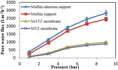
Flux of pure water at different pressures for supports and membranes.
Additionally, the mullite-alumina support exhibits more porosity compared to the mullite support, resulting in higher permeability. It is evident that the flux of pure water significantly decreases after the application of TiO2 and TiO2-ZrO2 layers. The results of pure water permeability tests for mullite and mullite-alumina supports, as well as MTZ and MATZ membranes, were recorded as 254, 382, 70, and 89 L bar−1 m-2h−1, respectively. For enhanced comparison, the results achieved for the pure water permeability of ceramic membranes are presented in Table 5.
Reference
Membrane
Pure water permeability
(L bar−1 m-2h−1)
Support
Intermediate
layerSelective
layer
(Lu et al., 2016)
No reported
TiO2
TiO2
35–40
(Da et al., 2016)
No reported
α-Al2O3
ZrO2
13
(Bouazizi et al., 2017)
Bentonite
−
TiO2
33
(Jafari et al., 2022)
mullite-zeolite-alumina
Zeolite
SiO2
489–690
This paper
mullite & mullite-alumina
TiO2
TiO2-ZrO2
70–382
3.2.2 Different salts rejection rate
To assess the rejection rate, various concentrations of salt solutions were prepared, and their pH was adjusted using nitric acid and sodium hydroxide. The results of MTZ membrane rejection for different salt solutions, namely NaCl, CaCl2, and MgCl2, are presented in Fig. 9. For all three salts at a pH of 7, the rejection percentage exhibits the lowest value due to the limited Donnan exclusion effect on ionic rejection. At a pH of 3, membrane rejection is attributed to its positive surface charge, resulting in the removal of Na+, Mg2+, and Ca2+ ions. Conversely, at a pH of 10, the membrane possesses a negative surface charge, leading to the removal of Cl¯ ions. Moreover, upon comparing the columns in Fig. 9, it becomes evident that with an increase in the concentration of salt solutions, the rejection percentage decreases. This phenomenon can likely be attributed to the reduction in the thickness of the double layer as a consequence of heightened salt concentration (Chen et al., 2015). Factors such as experimental conditions, sample heterogeneity, and measurement accuracy can contribute to the differences in error bar sizes (Fig. 9). Larger error bars indicate higher uncertainty in the measurements, while smaller error bars suggest more precision in the data.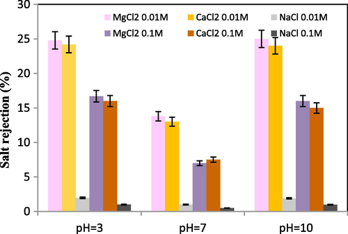
MTZ rejection of salt solutions at different pH, operating pressure 5 bar and temperature 25 ℃.
3.2.3 Oily wastewater treatment
Fig. 10 presents the permeability results of the final membranes based on the filtration time of oily wastewater with a COD of 1000 mg/L. Both MTZ and MATZ membranes underwent oily wastewater filtration at three different pressures. According to Darcy's law, an increase in pressure enhances flux; however, the accumulation of sediment on the membrane surface limits this effect. Elevated pressure causes oil droplets to compress onto the membrane surface, ultimately obstructing membrane pores. Consequently, conducting filtration at an optimal pressure that balances high flux with low sediment layer formation is crucial.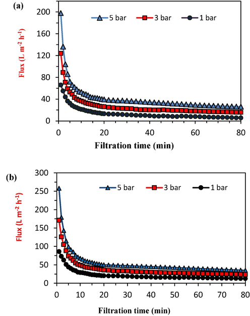
Flux of the final membranes in terms of oily wastewater filtration time (a) MTZ membrane, (b) MATZ membrane.
Fig. 11 illustrates the impact of increasing filtration pressure on COD rejection for MTZ and MATZ membranes. As depicted, the rejection percentage gradually increases with higher pressure, primarily due to the formation of a fouling layer on the membrane surface. At a pressure of 7 bars, MTZ and MATZ membranes achieved COD rejections of 98.65 % and 98 %, respectively. Further increases in operating pressure will progressively increase the sediment layer density until a point is reached where additional pressure increments no longer significantly affect flux or enhance the rejection percentage (Abbasi et al., 2010).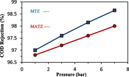
The results of increasing the pressure of filtration operation on COD rejection.
4 Conclusion
This study aimed to fabricate TiO2 and ZrO2 ceramic membranes using a coating method on mullite and mullite-alumina supports. To achieve this, two types of tubular supports—comprising mullite and mullite-alumina (50 %)—were manufactured using the extrusion method. Colloidal sols of TiO2 and TiO2-ZrO2 were prepared using the sol–gel method and subsequently applied to the ceramic supports via the dip-coating process. The subsequent step involved evaluating the membrane performance for treating oily wastewater. The outcomes of pure water permeability tests for mullite and mullite-alumina supports, as well as the final MTZ and MATZ membranes, yielded values of 254, 382, 70, and 89 L bar−1 m-2h−1, respectively. The comparison of salt rejection results at different acidic, alkaline, and neutral pH levels revealed that precise adjustment of the feed solution's pH substantially enhances the rejection rate. Furthermore, findings related to the filtration of oily wastewater using membranes indicated that higher pressure corresponds to an increased rejection rate. At a pressure of 7 bar, the COD rejection for MTZ and MATZ membranes reached 98.65 % and 98 %, respectively. It is recommended for future investigations to coat α-Al2O3 powder onto the supports prior to nanoparticle coating. This approach can gradually reduce surface pore sizes, leading to higher-quality subsequent coating operations.
CRediT authorship contribution statement
Iman Fooladi: Methodology, Investigation, Data curation. Parnian Ghanbarizadeh: Writing – original draft, Conceptualization. Ahmad Azari: Supervision, Project administration, Conceptualization. Mohsen Abbasi: Resources, Formal analysis, Conceptualization. Rahim Karami: Writing – review & editing, Conceptualization. Mohammad Akrami: Writing – review & editing, Validation, Supervision, Resources, Conceptualization.
Declaration of Competing Interest
The authors declare that they have no known competing financial interests or personal relationships that could have appeared to influence the work reported in this paper.
References
- Performance study of mullite and mullite–alumina ceramic MF membranes for oily wastewaters treatment. Desalination. 2010;259(1–3):169-178.
- [CrossRef] [Google Scholar]
- Omniphobic surface modification of silica sand ceramic hollow fiber membrane for desalination via direct contact membrane distillation. Desalination. 2022;532:115705
- [CrossRef] [Google Scholar]
- Preparation, characterization, and evaluation of TiO2-ZrO2 nanofiltration membranes fired at different temperatures. J. Membr. Sci.. 2018;564:691-699.
- [CrossRef] [Google Scholar]
- Ceramic monolith as microfiltration membrane: preparation, characterization and performance evaluation. Appl. Clay Sci.. 2018;161:456-463.
- [CrossRef] [Google Scholar]
- Development of a new TiO2 ultrafiltration membrane on flat ceramic support made from natural bentonite and micronized phosphate and applied for dye removal. Ceram. Int.. 2017;43(1):1479-1487.
- [CrossRef] [Google Scholar]
- Fundamentals of membrane top-layer synthesis and processing. In: Membr. Sci. Technol.. Vol Vol. 4. Elsevier; 1996. p. :259-329.
- [CrossRef] [Google Scholar]
- Burggraaf, A. J., & Cot, L. (Eds.). (1996). Fundamentals of inorganic membrane science and technology. Elsevier.
- Hydrophilic modification of Al2O3 microfiltration membrane with nano-sized γ-Al2O3 coating. Desalination. 2010;262(1–3):110-114.
- [CrossRef] [Google Scholar]
- Preparation of high-flux γ-alumina nanofiltration membranes by using a modified sol–gel method. Microporous Mesoporous Mater.. 2015;214:195-203.
- [CrossRef] [Google Scholar]
- Preparation of zirconia nanofiltration membranes through an aqueous sol–gel process modified by glycerol for the treatment of wastewater with high salinity. J. Membr. Sci.. 2016;504:29-39.
- [CrossRef] [Google Scholar]
- Robust superhydrophobic ceramic fiber braid for oil water separation. Ceram. Int.. 2023;49(7):11725-11729.
- [CrossRef] [Google Scholar]
- Polymer-derived porous SiOC ceramic membranes for efficient oil-water separation and membrane distillation. J. Membr. Sci.. 2019;579:111-119.
- [CrossRef] [Google Scholar]
- Contribution to porous mullite synthesis from clays by adding Al and Mg powders. J. Eur. Ceram. Soc.. 2009;29(1):31-38.
- [CrossRef] [Google Scholar]
- Preparation and development of porous ceramic membrane supports fabricated by extrusion technique. Chem. Eng. Trans.. 2016;55:277-282.
- [CrossRef] [Google Scholar]
- Performance enhancement of specific adsorbents for hardness reduction of drinking water and groundwater. Water. 2022;14(17):2749.
- [CrossRef] [Google Scholar]
- Amino acid retention with alumina γ nanofiltration membrane. J. Membr. Sci.. 2000;172(1–2):9-17.
- [CrossRef] [Google Scholar]
- Low-cost porous mullite ceramic membrane supports fabricated from kyanite by casting and reaction sintering. Ceram. Int.. 2016;42(4):4819-4826.
- [CrossRef] [Google Scholar]
- Fabrication and characterization of TiO2/ZrO2 ceramic membranes for nanofiltration. Microporous Mesoporous Mater.. 2018;260:125-131.
- [CrossRef] [Google Scholar]
- Preparation and characterization of photocatalytic titania–alumina composite membranes by sol–gel methods. J. Eur. Ceram. Soc.. 2011;31(15):2867-2875.
- [CrossRef] [Google Scholar]
- A new and economic approach to fabricate resistant porous membrane supports using kaolin and CaCO3. J. Eur. Ceram. Soc.. 2014;34(5):1329-1340.
- [CrossRef] [Google Scholar]
- Hong, Q., Shi-Da, L. I., & Xiao-Luo JIANG, J. H. (2011). Reparation and ions retention properties of TiO2 nanoiltration membranes. J. Inorgan. Mater., 26(3), 305-310.
- Elaboration and characterization of novel two-layer tubular ceramic membranes by coating natural zeolite and activated carbon on mullite-alumina-zeolite support: application for oily wastewater treatment. J. Asian Ceram. Societies. 2020;8(3):848-861.
- [CrossRef] [Google Scholar]
- Application of mullite-zeolite-alumina microfiltration membranes coated by SiO2 nanoparticles for separation of oil-in-water emulsions. J. Eur. Ceram. Soc.. 2022;42(13):6005-6014.
- [CrossRef] [Google Scholar]
- Ultra-low temperature co-sintering of water glass (WG)-bonded silicon carbide ceramic membranes for oil-water separation. J. Membr. Sci.. 2024;692:122311
- [CrossRef] [Google Scholar]
- Micro-structural optimization of supported γ-alumina membranes. J. Membr. Sci.. 2008;316(1–2):80-88.
- [CrossRef] [Google Scholar]
- Evaluation of structural/performance variation between α-Al2O3 and polyvinylidene fluoride membranes under long-term clean-in-place treatment used for water treatment. Desalination. 2022;538:115921
- [CrossRef] [Google Scholar]
- Comparison of extruded and pressed low cost ceramic supports for microfiltration membranes. J. Eur. Ceram. Soc.. 2015;35(13):3681-3691.
- [CrossRef] [Google Scholar]
- Fabrication of TiO2-doped ZrO2 nanofiltration membranes by using a modified colloidal sol-gel process and its application in simulative radioactive effluent. J. Membr. Sci.. 2016;514:476-486.
- [CrossRef] [Google Scholar]
- Luck, W. A. P. (1984). Synthetic Membrane Process Fundamentals and Water Applications. Water Pollution: A series of monographs; Belfort, G. Ed, 23.
- Piezoceramic membrane equipped with superwetting interface and in-situ ultrasound performance for efficient oil/water emulsion separation. Desalination. 2023;555:116545
- [CrossRef] [Google Scholar]
- Basic principles of membrane technology. Springer science & business media; 2012.
- Treatment of oily wastewater using low cost ceramic membrane: Comparative assessment of pore blocking and artificial neural network models. Chem. Eng. Res. Des.. 2010;88(7):881-892.
- [CrossRef] [Google Scholar]
- The effect of heat sterilization on key filtration performance parameters of a commercial polymeric (PVDF) hollow-fiber ultrafiltration membrane. Membranes. 2022;12(8):725.
- [CrossRef] [Google Scholar]
- Nicholas, P. C., & Cheremisinoff, A. (2002). Handbook of water and wastewater treatment technologies. Press. USA, Boston, Washington, 1, 33-37.
- Microporous TiO2 membranes with a cut off< 500 Da. J. Membr. Sci.. 2000;174(1):123-133.
- [CrossRef] [Google Scholar]
- Development and permeation properties of SiO2-ZrO2 nanofiltration membranes with a MWCO of< 200. J. Membr. Sci.. 2017;535:331-341.
- [CrossRef] [Google Scholar]
- Fabrication of a sol–gel derived microporous zirconia membrane for nanofiltration. J. Sol-Gel Sci. Technol.. 2012;62:208-216.
- [Google Scholar]
- Oily wastewater treatment by adsorption-MF hybrid process using PAC, natural zeolite powder and low cost ceramic membranes. Water Sci. Technol. 2017
- [CrossRef] [Google Scholar]
- Biological and chemical wastewater treatment processes. Wastewater Treatm. Eng.. 2015;150(10.5772):61250.
- [Google Scholar]
- Characteristics and retention properties of a mesoporous γ-Al2O3 membrane for nanofiltration. J. Membr. Sci.. 1999;163(2):229-237.
- [CrossRef] [Google Scholar]
- Preparation and properties of porous α-Al2O3 membrane supports. J. Am. Ceram. Soc.. 2006;89(6):1790-1794.
- [CrossRef] [Google Scholar]
- Silica–zirconia membranes for nanofiltration. J. Membr. Sci.. 1998;149(1):127-135.
- [CrossRef] [Google Scholar]
- Nanofiltration in non-aqueous solutions by porous silica–zirconia membranes. J. Membr. Sci.. 2001;185(2):253-261.
- [CrossRef] [Google Scholar]
- Salt retention in nanofiltration with multilayer ceramic TiO2 membranes. J. Membr. Sci.. 2002;209(2):379-389.
- [CrossRef] [Google Scholar]
- Poly (glycerol monomethacrylate)-encapsulated upconverting nanoparticles prepared by miniemulsion polymerization: morphology, chemical stability, antifouling properties and toxicity evaluation. Nanoscale Adv.. 2023;5(24):6979-6989.
- [CrossRef] [Google Scholar]
- Superhydrophobic β-Sialon-mullite ceramic membranes with high performance in water treatment. Ceram. Int.. 2021;47(6):8375-8381.
- [CrossRef] [Google Scholar]
- Flexible multifunctional self-expanding electrospun polyacrylic acid covalently cross-linked polyamide 66 nanocomposite fiber membrane with excellent oil/water separation and high pH stability performances. Sustainability. 2022;14(21):14097.
- [CrossRef] [Google Scholar]
- Oil deasphalting using PAN membranes with small pore size. Membrany i Membrannye Tehnologii. 2023;13(6):521-534.
- [CrossRef] [Google Scholar]


