

Translate this page into:
Study on the corrosion behavior of polymeric nanocomposite coatings containing halloysite nanotubes loaded with multicomponent inhibitor
⁎Corresponding authors. ramazank@qu.edu.qa (Ramazan Kahraman), shakoor@qu.edu.qa (R.A. Shakoor)
-
Received: ,
Accepted: ,
This article was originally published by Elsevier and was migrated to Scientific Scholar after the change of Publisher.
Peer review under responsibility of King Saud University.
Abstract
In the present study, the halloysite nanotubes (HNTs) were loaded with a multicomponent inhibitor (LHNT) comprising mainly benzotriazole (BTA), sodium benzoate (SB), and lauric acid (LA) via the vacuum cycling method. The successful loading of the BTA + LA + SB inhibitor has been confirmed by the TGA, FTIR, and BET analyses. The TGA analysis has determined ∼ 14% loading of the BTA + LA + SB into the HNTs. Moreover, UV–vis analysis shows that the time and pH-dependent have incremental release of the multicomponent inhibitor in various studied media. The composite coatings (LHNT COAT) were developed by reinforcing the 3 wt% of LHNTs into the epoxy matrix. The corrosion protection of the developed LHNT COAT was enhanced by 99.6% and 98.88% compared to the blank epoxy and unloaded HNT coatings, respectively. This improvement in the corrosion behavior can be attributed to the active release of the multicomponent inhibitor, as was also demonstrated by the electrochemical impedance spectroscopic (EIS) test. It is further predicted that the improved corrosion inhibition efficiency of LHNT COAT may be due to the formation of some components produced from the reaction of the inhibitor components or from the inhibitor reaction with the corrosive medium. The high corrosion resistance of LHNT COAT makes it attuned to several industrial applications.
Keywords
HNTs
Inhibitor
Corrosion
Self-healing
Smart coatings
EIS

1 Introduction
Corrosion prevention can be achieved by selecting appropriate design, corrosion-resistant alloys, anti-corrosion coatings, corrosion inhibitors, cathodic protection, anodic passivation, salt removers, and regular washing (xxxx; Honarvar Nazari et al., 2022; Zahidah et al., 2017). As the metallic surfaces are always exposed to harsh environmental factors, there is always a possibility of cracks or unexpected damage. One of the most used techniques to protect metallic surfaces from degradation due to corrosion is the application of coatings which create a barrier by preventing the direct contact of the metals with water and corrosive ions. There are three types of anti-corrosion coatings based on the coating material which are metallic, organic, and inorganic coatings. Metallic coatings provide cathodic protection by galvanic corroding if the metal is less noble than the base metal(Honarvar Nazari et al., 2022; Qian et al., 2015). Otherwise, the defects will cause pitting corrosion to the base metal. In addition, inorganic coatings protect the metal using a barrier protection mechanism. However, some treatments used in the inorganic coatings cause a conversion of the surface layer into metal oxide or hydroxide film which can enhance the interfacial attractions between the coating and the metal. Hence, the organic coatings can consider an excellent option for corrosion protection which provide barrier protection and active inhibition by the species that can be reinforced to them. There is a high possibility for micron cracks occurrence which are very difficult to be visible and the coating degradation by temperature or UV radiation leads to the opening of the coating pores and crack promulgation which facilitate the diffusion of salts and water to the metal interface ending up with corrosion initiation. Hence, nanocomposite coating is a developed coating type that involves nanoparticles/nanocontainers in addition to the coating which enhances the coating features based on the distinctive chemical, physical, and physiochemical properties of the nanoscale materials(Zahidah et al., 2017). Especially, the coatings with passive and active protection have been proposed in recent years(Wan et al., 2021). Several nano and micro containers have been used by researchers in the recent years as reservoirs for the inhibitors and self-healing agents such as montmorillonite nanoparticles(Ghazi et al., 2015), Nano-TiO2(Radhakrishnan et al., 2009), LDH(Mohedano et al., 2017; Zhang et al., 2015; Hang et al., 2012), Polypyrrole-TiO2(Kartsonakis et al., 2013), NaY zeolite(Ferrer et al., 2014), Bio-based micro/nanoparticles(Denissen and Garcia, 2017), CeO2 nanoparticles(Wang et al., 2021), Zirconia nanoparticles(Habib et al., 207 (2021)), Yttrium Oxide(Nawaz et al., 2021), Halloysite Nanotubes (HNT) (Khan et al., 2020), cellulose microfibers (CMFs) (Nawaz et al., 2020), urea-formaldehyde microcapsules (UFMCs)(Khan et al., 2019; Ismail et al., 2021), Melamine urea-formaldehyde microcapsules (MUFMCs)(Hassanein et al., 2021). Among all the nanocontainers, clays with a hollow structure such as halloysite nanotubes act as an excellent nanocontainer for the loading of active agents because of their high surface area, good dispersion, ability to load several active agents simultaneously, high loading rate, high capacity, high adsorption rate, high aspect ratio, highly porous and non-toxicity (Kamble et al., 2012; Izadi et al., 2019). Generally, HNT length ranges between a few microns to 30 µm with an external diameter and internal diameter of 30–190 nm and 10–100 nm respectively. Moreover, it is a low-cost material at $4/kg. The outer surface contains tetrahedral silicate SiO2 layers whereas the inner lumen consists of gibbsite octahedral layers of Al2O3. Recently, several researchers used HNTs as nanocontainers for corrosion inhibitors for corrosion prevention(Wu et al., 2021; Xu et al., 2019; Mahmoudi et al., 2020; Asadi et al., 2019). Wang et al., loaded HNTs with 8-Hydroxyquinoline (8-HQ) corrosion inhibitor by negative vacuum and encapsulated them with-8-HQ complex stopper, and then reinforced the Cu-8-HQ@HNTs into an epoxy matrix obtaining a highly resistive coating against corrosion in the acidic media(Wang et al., 2019). In addition to the function of HNT as an excellent smart carrier, it can improve the mechanical properties when incorporated into the corrosion protection coatings. Kiran et al. investigated the mechanical properties of carbon fabric reinforced epoxy matrix composites which were prepared with the addition of HNTs and enhances the tensile strength, modulus of elasticity, flexural strength, and flexural modulus up to 82%, 26.8%, and 29% respectively(Kiran et al., 2022). The applications of the HNTs are not limited to the corrosion protection field but they are extended into the food packaging and for surface protection in the field of cultural heritage treatment and conservation. Lisuzzo et al., designed novel nanocomposite films based on hydroxypropyl cellulose and paraffin/halloysite hybrid microspheres for the application as protective material for packaging purposes and restoration and conservation of cultural heritage(Lisuzzo et al., 2021). Moreover, the HNTs are used in the deacidification field. Lisuzzo et al., developed a novel system for the loading of HNTs with an alkaline reservoir (MgO nanoparticles) that can be used for the treatment of cellulose-based paper(Lisuzzo et al., 2021). However, the effect of loading inorganic nanocarrier (specially HNT) with multiple inhibitors is not yet studied from the corrosion protection and the inhibition mechanism perspectives. Furthermore, the usage of sodium benzoate (SB)(Seetharam et al., 2022; Lin et al., 2018; Talebian et al., 2018), lauric acid (LA)(Xu et al., 2020; Yang et al., 2018; Lu et al., 2009), and benzotriazole (BTA)(Walker, 1970; Finšgar and Milošev, 2010) as inhibitors proved the high barrier and inhibition ability. In this work, the inhibitor (BTA + LA + SB) consists of three main components (lauric acid, benzotriazole, and sodium benzoate) which is used as a coolant and corrosion inhibitor in the utility section in one of the petrochemical industries, has been loaded into the HNTs (LHNT). The LHNT nanocontainers were reinforced into an epoxy matrix to develop LHNT COAT to study the anti-corrosion behavior of the LHNT COAT, the reaction behavior of the inhibitor components, release profile of the inhibitor through the time on different media and the corrosion inhibition mechanism of the BTA + LA + SB inhibitor. It is anticipated for the inhibitor to enhance the corrosion resistance and extend the lifetime of the LHNT COAT compared to the loading of HNT with a single inhibitor.
2 Experimental section
2.1 Materials
The chemicals used in the loading of HNTs are halloysite nanotubes (HNTs) used as nanocontainers were purchased from Sigma-Aldrich Darmstadt, Germany, multicomponent inhibitor (BTA + LA + SB) with classified composition (as received from a local source) and deionized water.. Moreover, the materials used in the coating preparation are epoxy resin (Epon resin 815C), triethylenetetramine (as an epoxy hardener), carbon steel sheets as substrates (with the composition of 0.21% C, 0.30% P, 0.04% S, 0.20% Cu and 99.18% Fe) and thickness of 1.25 mm, ethanol (for cleaning the carbon steel surface from any contaminations before coating) and NaCl (to prepare 3.5 wt% NaCl solution with pH 6.7).
2.2 Loading of HNTs
The BTA + LA + SB inhibitor was loaded into the HNTs by vacuum cycling methods reported in literature and prove its efficiency in the loading of the HNT nanocarriers(Lisuzzo et al., 2019; Lisuzzo et al., 2021). Firstly, the saturated solution of the inhibitor was prepared by magnetically stirring of 22 ml of ethanol and 0.66 ml of the multicomponent inhibitor at room temperature for 2 hr. Then, 3.2 g of HNTs were added to the prepared inhibitor solution and stirred continuously at room temperature for 30 min to ensure complete dispersion. Then the HNTs/drug suspension was subjected to ultrasonication for 5 min and placed in a vacuum furnace for 24 hr to allow the reduction in the pressure conditions into 0.01 atm. Then, the slurry was centrifuged and washed three times with water to remove the unbound molecules and dried under vacuum at room temperature for 24 hr. Fig. 1 illustrates the HNT loaded with BTA + LA + SB inhibitor.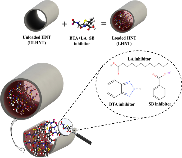
Loaded HNT (LHNT) with BTA + LA + SB inhibitor.
2.3 Preparation of substrates and coatings
Fig. 2 demonstrates the coating preparation process of the loaded HNT coating (LHNT COAT). The steel substrates were polished employing a grinding machine (Forcipol 1 V, Metkon, Turkey) using SiC abrasive papers (80 and 120c). The polished substrates were washed with distilled water and dried in air. After that, the steel substrates were cleaned using acetone or ethanol before applying the coatings. Three different coatings were prepared which are plain epoxy coating, unloaded HNT epoxy coating, and loaded HNT epoxy coating (LHNT COAT). The plain epoxy coating was prepared by mixing the epoxy and the hardener with 5:1 ratio under stirring and vacuum at 60 °C for 15 min. However, the loaded HNT coating (LHNT COAT) and unloaded HNT coatings were prepared by reinforcing 3 wt% of the loaded HNTs (LHNT) and unloaded HNTs into the epoxy matrix respectively. In detail, the preparation was carried out by mixing epoxy with the loaded and unloaded HNT separately with stirring at 60 °C under vacuum for one hour to enhance the dispersion of the loaded and unloaded HNT in the epoxy matrix, followed by sonication. After the mixture cooled down, the hardener was added under vacuum and stirring for 15 min. Finally, the mixture was sonicated for 5 min to remove the air bubbles from the epoxy then applied into the steel surface and left to dry in the air.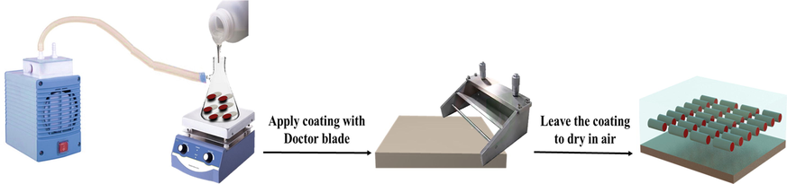
Loaded HNT Coating (LHNT COAT) preparation process.
2.4 Characterization
The morphology of the loaded and unloaded (as received) HNT was studied by a field emission scanning and transmission electron microscope (SEM-TEM-Nova Nano-450) coupled with an EDX analyzer which analyzes the elemental composition of the loaded and the unloaded HNT. The thermal stability of prepared coatings (blank epoxy, ULHNT COAT and LHNT COAT) and the HNT (loaded and unloaded) was inspected by thermal gravimetric analysis (TGA, 4000, Perkin Elmer, USA). The test was conducted in a temperature range of 40 °C −600 °C by applying heating rate of 10 °C/min. Fourier-transform infrared spectroscopy (FTIR) test was conducted on the loaded HNT, unloaded HNT, and the inhibitor applying FTIR Frontier instrument (Frontier-MIR, Perkin Elmer, USA). The test was carried out to confirm the loading of the inhibitor in the HNT using the capability of each bond in the tested materials to absorb infrared radiation at a certain absorption frequency range, which considered is a fingerprint for each bond. The FTIR analysis was carried out in the range of 4000 cm−1 to 500 cm−1. Electrochemical impedance spectroscopy (EIS) was performed using the Gamry device (Reference 3000, Potentiostat/Galvanstate, USA) to examine the corrosion resistance of the developed coatings when exposed to mechanical damage in 3.5 wt% NaCl solution with pH of 6.7 with an exposed area of 0.765 cm2, and a platinum wire was used as a counter electrode while an Ag/AgCl electrode was employed as a reference electrode. The corrosion test was carried out at 25 °C at the frequency range of 0.01 to 100000 Hz with an AC voltage of 10 mV. The specific surface area and pore volume of the loaded and unloaded HNT particles were measured using BET (Brunauer-Emmett-Teller) technique by surface area analyzer (Micromeritics ASAP 2420, USA) to predict the loading of the inhibitor into HNT particles. Furthermore, UV − vis spectroscopic analysis (LAMBDA 650 UV–vis Spectrophotometer, PerkinElmer, USA) was applied to analyze the release of the inhibitor from the loaded HNTs (LHNT). Various solutions were prepared by the addition of 0.05 g of the loaded HNTs to study the release behavior of the loaded inhibitor at different pH values (2, 5, 7, 9, 14) concerning time. The pH of the solutions was adjusted by adding HCl and NaOH solutions dropwise.
3 Results and discussion
3.1 SEM, TEM, elemental mapping, and EDX observation
Fig. 3 shows the TEM images of the loaded and unloaded HNT which revealed a nanostructure of the HNT. Moreover, the difference between the loaded and unloaded HNT can be noticed in the dark lumen of the loaded HNT shown in Fig. 3(b) unlike the light color of the HNT lumen, shown in Fig. 3(a). This dark color in the loaded HNT showed the loading of the inhibitor in the HNT. Furthermore, Fig. 4(a,b) shows the morphological structure observed by SEM analysis of the unloaded and loaded HNT, respectively. Fig. 4(a) represents the tubular structure of the unloaded HNT without any cluster. However, Fig. 4 (b) shows the incorporation of some clusters with the loaded HNT, which is an indication of sticky or undehydrated texture of the surface of the HNT due to the loading of the inhibitor. Moreover, the SEM micrographs represent a variation in the HNT particle sizes. Furthermore, the SEM micrographs show a slightly puffed structure of the loaded HNT compared with the unloaded HNT. In addition, Fig. 4(c,d) presents the EDX analysis of the unloaded and loaded HNT, respectively. In Fig. 4(c), the EDX of the unloaded HNT shows the presence of oxygen, aluminum, and silica which are the elements that formed the HNT particle (Al2Si2O5(OH)4·2H2O). However, it can be observed in Fig. 4(d) the involvement of carbon, nitrogen, and sodium with the previously mentioned elements (oxygen, aluminum, and silica), which indicates the successful loading of the BTA + LA + SB inhibitor in the HNT nanoparticles. The presented findings agree with the previously reported results in the literature (Khan et al., 2020; Hassanein et al., 2021; Wu et al., 2016).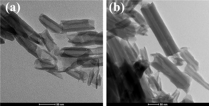
TEM for (a) unloaded HNT and (b) loaded HNT.
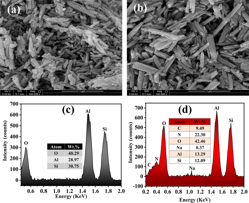
SEM micrographs of (a) unloaded HNT and (b) loaded HNT and EDX of (c) unloaded HNT and (d) loaded HNT.
3.2 Thermal stability
TGA analysis was conducted for the unloaded, loaded HNT (LHNT), the inhibitor, unloaded HNT epoxy coating (ULHNT COAT) and loaded HNT coating (LHNT COAT), and blank epoxy coating, which is illustrated in Fig. 5. Fig. 5(a) shows that the mixed inhibitor was loaded successfully in the HNT nanocontainers with approximately 14% loading. The thermal spectrum of the loaded and unloaded HNT shows a declination in the temperature range of 400 °C–550 °C, which corresponds to HNT decomposition(Khan et al., 2020). Unlike the unloaded HNT thermal spectrum, which has one weight-loss stage, the LHNT thermal spectrum indicates three main weight loss stages in the temperature ranges of 30 °C–70 °C, 70 °C–450 °C, and 450 °C–550 °C. The first weight-loss stage corresponds to the degradation initiation of a mixed inhibitor loaded in the HNT, which can be observed in the thermal spectrum of the inhibitor. Moreover, the second weight-loss stage of the loaded HNT corresponds to a 5% weight loss which is a minor weight loss that can be attributed to the degradation of the inhibitor left on the surface of the HNTs, especially that the boiling points of the inhibitor’s main components are in the temperature range of this stage. Moreover, the weight loss at 100 °C can be due to the full evaporation of any water or moisture presented in the sample. It can be observed that the trend of the loaded and unloaded HNT TGA graphs are very similar (the degradation of the loaded HNT is not affected by the early degradation of the inhibitor), which shows that the HNT is an excellent reservoir for the inhibitor. In addition, Fig. 5(b) shows the TGA profile of the reference coating, ULHNTCOAT and LHNT COAT. The presented TGA of the coatings are similar in the thermal behavior of the coatings because of the high incorporation of epoxy in them (97%). Hence, the thermal behavior of all the coatings is very close to the reference coating with a minor deviation because of the existence of the HNT loaded with the mixed inhibitor in the LHNT COAT. The results are in agreement with the previously reported studies(Izadi et al., 2019).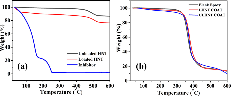
TGA of (a) loaded, unloaded HNT and inhibitor and (b) Blank epoxy, ULHNT COAT and LHNT COAT.
3.3 FTIR analysis
FTIR analysis was conducted to confirm the loading of BTA + LA + SB inhibitor in the HNTs nanocarriers. Fig. 6 represents the FTIR spectra of the unloaded HNTs, loaded HNTs, and BTA + LA + SB inhibitor. As can be seen in the loaded and unloaded HNT spectra, the peaks at 3689 and 3619 cm−1 are for the stretching vibration bands of Al2OH, peaks at 1002 cm−1 and 905 cm−1 are for Si-O and Al-OH, respectively(Khan et al., 2020; Hassanein et al., 2021). Moreover, a peak can be observed at 550 cm−1 in the unloaded HNT spectrum because of the deformation of the Al-O-Si group (Xing et al., 2018). The spectrum of the inhibitor shows the characteristic absorption peaks of lauric acid, sodium benzoate, and benzotriazole. The inhibitor’s graph presents the overlapping stretching vibration bands of the secondary amine (N − H) and OH at 3341 cm−1. Furthermore, the peaks at 2962 cm−1, 2850 cm−1, 1037 cm−1, and 1671 cm−1 represent the stretching of C-H, C-O, and C = O, respectively. C-H and C-O bonds reflect the presence of lauric acid in the inhibitor, while the C = O bond reflects the presence of lauric acid and sodium benzoate. In addition, the peak at 1450 cm−1 is for the stretching of the aromatic C = C bond present in sodium benzoate and benzotriazole. Peaks at 1340 cm−1 and 1210 cm−1, 675 cm−1 are for the stretching of C-N, N = N, and monosubstituted out-of-plane bending of = C-H in benzotriazole, respectively (Hassanein et al., 2021; Singh et al., 2017). Hence, all the peaks of the inhibitor and unloaded HNT are presented in the loaded HNT spectrum, which confirms a successful loading of the BTA + LA + SB inhibitor in the HNTs. The results are in agreement with the previously reported studies(Khan et al., 2020; Izadi et al., 2019).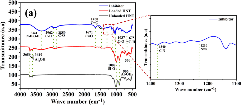
FTIR of inhibitor, loaded HNT and unloaded HNT.
3.4 BET analysis
BET analysis has been conducted to confirm the loading of BTA + LA + SB inhibitor into HNT nanoparticles. The test measured the surface area and pore volume of the loaded and unloaded HNT using N2 adsorption on a gradual increase in pressure. Fig. 7 presents the nitrogen adsorption isotherm of the unloaded and loaded HNT. As per IUPAC categorization, the adsorption isotherms of the loaded and unloaded HNT follow type III; this type is formed when the interactions between the adsorbed molecules are more robust than the interaction between the adsorbent surface and adsorbate(Zhang, 2016). As shown in Table 1, the specific surface area and pore volume of the loaded HNT decreased compared with the specific surface area and the pore volume of the unloaded HNT. This decrease indicates a successful loading of the BTA + LA + SB inhibitor in the HNT nanoparticles which cause a blocking/filling of the HNT(Habib et al., 207 (2021); Khan et al., 2020; Hassanein et al., 2021).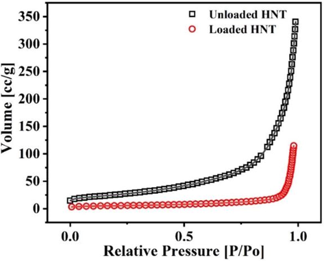
Nitrogen adsorption isotherm of the unloaded and loaded HNT.
Unloaded HNT
Loaded HNT
BET SSA (m2/g)
115.319
19.371
Total Pore Volume (cc/g)
0.5292
0.1783
3.5 Electrochemical impedance spectroscopy (EIS)
EIS technique was conducted to evaluate the anti-corrosion capability of the ULHNT COAT and LHNT COAT by exposing the developed coatings to 3.5 wt% NaCl solution with pH of 6.7 at room temperature for 15 days. Fig. 8 shows the two-time constant electrical circuit used in the fitting of EIS data of the coatings. Some parameters have been used in the electrical circuit, such as Rs, Rpo, Rct, CPE1, and CPE2, referring to the solution resistance, pore resistance, and charge transfer resistance at the metal interface, constant phase element for single-layer coating, and double-layer coating respectively. The continuous phase elements express the non-homogeneity and roughness of the surface because the species adsorbed and formed a passive protective film(Habib et al., 207 (2021)). Furthermore, it is related to the non-uniformity in the current spreading over the coating surface(Benoit et al., 2016). CPE can be converted into ideal capacitance (C) only if the n value is less than 0.75(Benoit et al., 2016; Hirschorn et al., 2010). Hence, the CPE values were converted into ideal C by the following equation(Sliem et al., 2019):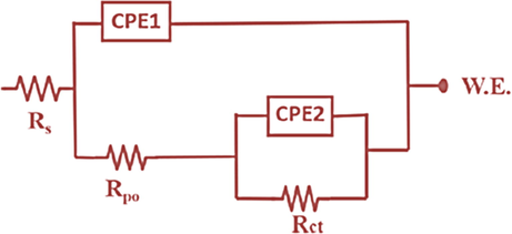
Equivalent electrical circuits used for EIS fitting of ULHNT COAT and LHNT COAT.
Where Y0 = CPE1.
Fig. 8 shows the equivalent electrical circuit used to fit the EIS data of ULHNT COAT and LHNT COAT. Moreover, the goodness of fit (Chi-square χ2) which used to test the extent of matching between the fitted data and experimental data was obtained from Gamry analyst software after the fitting of ULHNT COAT and LHNT COAT EIS data which calculated by the software using the following equation:
Where , Z is the impedance in ohms.
Fig. 9 represents the fitted bode graph and phase angle graph of ULHNT COAT and LHNT COAT and the raw EIS data are shown in Figure S1. The bode graph represents the resistance of the coating underexposing control mechanical damage (scratch) to the NaCl solution as a corrosive solution which facilitates the penetration of the chloride ions through the coating. The resistance of LHNT COAT was measured at 0, 3, 6, 9, 12, and 15 days of immersion. However, the resistance of ULHNT COAT was measured at 0, 3 and 6 days of immersion. The continuous immersion of the coating in the NaCl solution stimulates the inhibitor release due to the change in the localized pH of the interface between the coating and the steel substrate(Khan et al., 2020; Arjmand and Adriaens, 2012). A study has been carried out on the anti-corrosion behavior of the blank epoxy coating in 3.5 wt% NaCl as a reference in our previously reported work (Khan et al., 2020; Ismail et al., 2021). The studies highlighted that the charge transfer resistance at low frequency impedance spectra of the reference coating (blank epoxy) after 72 hr of immersion was
MΩ.cm2. Fig. 9(a,b) presents the bode graph and phase angle of the unloaded HNT epoxy coating (ULHNT COAT) which shows a decrease in the charge transfer resistance at low frequency impedance spectra.For the bode graph), the charge transfer resistance at low frequency impedance spectra was decreased from 7.00 MΩ.cm2 to 0.54 MΩ.cm2 in day 0 to day 6. Compared to the refence coating (blank epoxy) the ULHNT COAT has a higher resistance at the beginning of the experiment which can be attributed to the reinforcement of the HNT nanocontainers in the epoxy coating which acts a filler. In both coatings, the resistance decreased after a short immersion time due to the absence of an inhibitor which can delay the corrosion, extend the lifetime of the coating and enhance the corrosion resistance with the immersion time.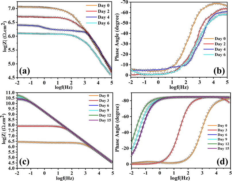
(a) Bode graph of ULHNT COAT, (b) Phase angle of ULHNT COAT, (c) Bode graph of LHNT COAT and (d) Phase angle of LHNT COAT.
Contrary to the blank epoxy coating and the unloaded HNT coating, the LHNT COAT shows a gradual increase in the low-frequency range. For the bode graph,) the charge transfer resistance at low frequency impedance spectra was increased from day 0 to day 12, which corresponds to 3.00 MΩ.cm2 to 60.00 GΩ.cm2 as shown in Fig. 9(c). The increase in the resistance for 12 days of immersion is because of the BTA + LA + SB inhibitor, which enhances the barrier properties and compensates for the change in the localized pH in the interface between the epoxy coating and the metal substrate. However, after day 12 of immersion, the charge transfer resistance at low frequency impedance spectra decreases gradually from 60.00 GΩ.cm2 to 50.00 GΩ.cm2 until 15 days of continuous immersion, which corresponds to a 16% decrease compared with the resistance value after the twelfth day of immersion (the highest resistance value). In addition, the corrosion inhibition efficiency of the LHNT COAT was calculated concerning the blank epoxy coating and unloaded HNT epoxy coating to be 99.6% and 98.88%, respectively. Moreover, the phase angle shows a decreasing trend in the low-frequency range after the twelfth day of immersion from −30˚ to −10˚ as shown in Figure 9(d). This decreasing behavior reveals the complete releasing of the inhibitor during twelve days of immersion which can delay the corrosion activity by the adsorption of the inhibitor on the steel surface, which reduces the chance of direct contact between the steel surface and the corrosive electrolyte. However, in general, the corrosion inhibitor does not have the full capability to heal the scratch of the coating, which creates a path through the coating for the corrosive electrolyte. Hence, as the inhibitor releasing rate decreases with the immersion time, the metal becomes less protected, facilitating the electrolyte access to the metal surface and the coating-metal interface. However, the multicomponent inhibitor (BTA + LA + SB) shows a slightly stable and longer-term anti-corrosion behavior compared with the ones reported in previous studies which developed epoxy coatings with loaded HNT using one or two inhibitors (as shown in Table 2) because of the excellent barrier property that has been enhanced by the presence of the currently studied inhibitor.
System
Low frequency impedance
Period (days)
Reference
HNT-imidazole and dodecylamine/ epoxy
5.62 × 10⁵ Ω cm2
7
(Khan et al., 2020)
HNT-BTA/ epoxy
6132 Ω cm2
8
(He et al., 2015)
HNT-BTA/ epoxy
4.19 GΩ cm2
9
(Hassanein et al., 2021)
Table 3 shows all the electrochemical parameters used in the fitting of the EIS data of the ULHNT COAT and LHNT COAT after 6 days and 15 days of immersion in 3.5 wt% NaCl electrolyte respectively. As can be seen in Table 3, Rpo values of ULHNT COAT decreased gradually for six days of immersion from 8.51e5 Ω.cm2 to 5.39e5 Ω.cm2 which indicating a poor corrosion resistance of the defected areas against the corrosive media because of the absence of inhibitor. Furthermore, Rct experiences the same decreasing trend of the Rpo which indicates the low resistance of the interface between the steel surface and coating because there is no loaded inhibitor in the HNTs to form a passive layer which can protect the surface of the steel. In addition, CPE1 and CPE2 values show an incremental trend that indicates low protection ability of the coating. However, Rpo values of the LHNT COAT increased continuously for twelve days of immersion from 1.584e6 Ω cm2 to 20.48e9 Ω cm2 which is an indication for the high anti-corrosion and barrier properties of the scratched areas due to the successful release of the inhibitor which can delay the corrosion process for a certain period because of the adsorption of the corrosion inhibitor at the steel surface(Hassanein et al., 2021). However, after 15 days of immersion, Rpo starts to decrease gradually to 19.03e9 GΩ.cm2 because of the deterioration of the barrier property of coatings and electrolyte uptake through the scratch after healing. However, the Rpo value after 15 days of immersion is still 98% higher than its value at the beginning of the experiment. Moreover, Rct values have the same increasing and decreasing trends as the Rpo values, which indicates the high resistance of the interface between the steel surface and coating because of the protective layer formation due to its absorption on the exposed or corroded steel surface which provides a self-healing capacity(Wan et al., 2021; Wan et al., 2022). This layer starts deteriorating after the 15th day of immersion results with a decreasing in Rct. Furthermore, CPE1 and CPE2 values show a decremental trend that reveals the coatings' capacitive behavior and high protection ability.
Coating type
Immersion time (days)
Rpo (Ω.cm2)
CPE1 (sn Ω−1 cm−2)
CPE2 (sn Ω−1 cm−2)
Rct (Ω.cm2)
n
Cdl (µF/cm2)
Goodness of fit
Unloaded HNT coating (ULHNT COAT)
0
8.51 ± 68.9e5
134.5 ± 93.7e-12
2.735 ± 36.5e-12
6.55 ± 0.283 e5
0.88 ± 0.057
–
45.49e-3
2
7.74 ± 56.97e5
204.4 ± 32.3e-12
466.3 ± 0.0273e-11
5.75 ± 0.247 e5
0.87 ± 0.0467
–
79.68e-3
4
6.32 ± 46.7e5
328.9 ± 54.58e-11
648.6 ± 394.4e-11
4.36 ± 38.4e5
0.75 ± 0.1356
–
57.57e-3
6
5.39 ± 16.45e5
104.2 ± 68.39e-10
35.04 ± 85.48–9
3.36 ± 8.92e5
0.67 ± 0.0345
6.43e-10
36.25e-3
Loaded HNT epoxy coating (LHNT COAT)
0
1.584 ± 3.49e6
145.1 ± 12.78e-12
125.8 ± 510.4e-12
6.26 ± 110.5e6
0.0733 ± 0.455
5.08e-49
9.136e-3
3
37.74 ± 103.6e6
111.1 ± 16.15e-12
122.2 ± 25.30e-12
38.93 ± 108.5e6
0.998 ± 899.9e-3
–
64.23e-3
6
21.49 ± 46.86e9
105.7 ± 2.991e-12
25.27 ± 87.11e-12
69.34 ± 219.8e9
0.201 ± 502.8e-3
2.9e-7
15.21e-3
9
16.75 ± 4.639e9
101.8 ± 1.132e-12
9.771 ± 76.78e-12
75.94 ± 330e9
0.337 ± 0.108
5.69e-9
5.883e-3
12
20.48 ± 20.74 e9
101.6 ± 1.008e-12
75.17 ± 2.687e-12
93.33 ± 24.48e9
0.456 ± 99.03e-3
1.49e-9
7.677e-3
15
19.03 ± 10.76e9
99.90 ± 86.7e-12
19.41 ± 3.510e-12
67.65 ± 11.32e9
0.537 ± 0.0693
5.19e-10
7.986e-3
3.6 Corrosion inhibition mechanism
In the proposed system (LHNT COAT), a controlled scratch has been carried out on the coating surface, which causes corrosion inhibition due to the releasing of the mixed inhibitor in the scratched area. As discussed in section 3.5, the developed coating witnessed an excellent and stable anti-corrosion behavior when exposed to the NaCl electrolyte, which caused a change in the localized pH(Khan et al., 2020; Arjmand and Adriaens, 2012). As a result, the inhibitor was released to adapt to this change by forming a thin film in the defected area acting as a temporary barrier against the passage of the corrosive ions. As the inhibitor is used in the industry and received as a mixture, there is a high probability of incorporating some additives/ solvents to adjust or change some of the inhibitor functionalities upon the needed industrial usage. Moreover, complicated and random reactions of the inhibitor components may be possible, which can change the inhibitor structure. Hence, in the current study, the corrosion inhibition reaction mechanism will be discussed based on the known main components (lauric acid, benzotriazole, and sodium benzoate). Considering this, there are different possible reaction scenarios based on the main components of the inhibitor. One of these scenarios is the formation of the benzoate group by the dissociation of sodium benzoate, which is known for its high dissociation in the aqueous environments forming an anion of benzoic acid(Benzoate, 2022) which can reduce the corrosion activity on the steel surfaces(Bilgiç, 2002; Alahiane et al., 2020). The adsorptive characteristics of benzoic acid affect the corrosion resistance capacity because of the chemical species’ nature, which is present in the aqueous form of benzoic acid. As a carboxylic acid, benzoic acid forms stable dimeric structures that provide higher protection for the steel under predominating conditions. In addition, the benzoate group can react with the dodecyl group, which resulted from the dissociation of the hydrogen ion and breaking of the oxygen double bond of the lauric acid-forming benzoic acid 2-oxododecyl ester compound containing ester and benzoate group which is known for their excellent corrosion inhibition property(Blustein et al., 2005; Gao et al., 2015; Bartley et al., 2003). Generally, the benzoate group acts as an effective inhibitor for iron in natural and essential environments(Zor, 2002). In another scenario, the production of benzyl laurate or sodium laurate resulted from replacing hydrogen in the lauric acid by benzene group or sodium ion, respectively. Benzyl laurate or sodium laurate can decrease the corrosion rate by forming a monomolecular adsorption film on the steel surface, inhibiting anodic and cathodic processes upon adsorption behavior following Flory–Huggins isotherm model(Zhu et al., 2010). The third possible scenario is the formation of dodecanone by the OH dissociation under intense heating or the presence of Lewis acid (such as BF3 or SOCl2)(Reusch, 2020) that could act as an inhibitor to the steel surface against corrosion(Khadraoui et al., 2014; Allal et al., 2019). However, it is not anticipated for the benzotriazole to be reacted because of its stability against acids and alkalis, oxidation and reduction processes, and heating(Zhong et al., 2010). Furthermore, the released active species of BTA + LA + SB inhibitor adsorbed on the metal surface by replacement of the water molecules which were occupying the surface. Hence, the inhibitor is adsorbed on the steel substrate surface by forming Fe-(inhibitor)ads intermediate that forms a layer on the surface. The adsorbed film on the steel substrate acts as a protective layer (barrier) for the corrosion media (i.e., NaCl), ameliorating the anti-corrosion property of the metal surface. Fig. 10 represents the probably formed species by the reaction of the inhibitor’s main components and the mechanism of inhibition of the developed HNT coating (LHNT COAT) by the response of the inhibitor with the steel. Fig. 11 represents the elemental mapping of the scratched area of ULHNT COAT and LHNT COAT after exposing to the NaCl electrolyte which confirms the release of the BTA + LA + SB inhibitor on the substrate surface. As can be seen in Fig. 11, the levels of carbon, nitrogen and sodium and oxygen increased in the LHNT COAT compared with the ULHNT COAT which represents the presence of the inhibitor.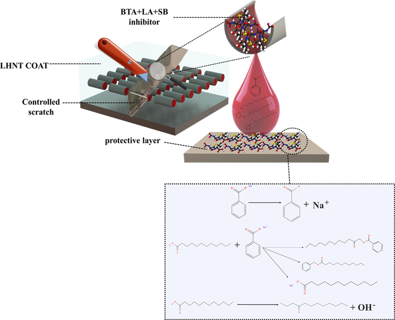
Inhibition analysis of LHNT COAT and BTA + LA + SB inhibitor.
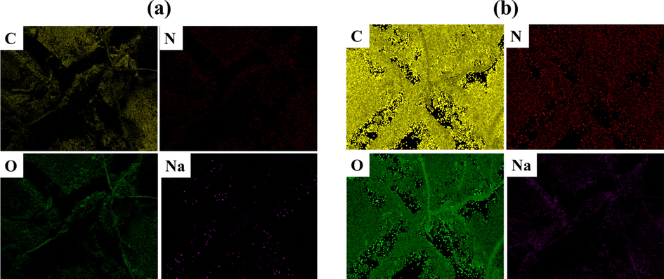
Elemental mapping for the scratched area of (a) ULHNT COAT and (b) LHNT COAT.
3.7 UV–vis analysis
The release of the BTA + LA + SB inhibitor from the loaded HNT (LHNT) was studied through UV–vis spectroscopy. Hence, the loaded and unloaded HNT were dispersed separately in 3.5 wt% NaCl solutions with pH values of 2, 5, 7, 9 and 14. The UV spectra of the loaded and unloaded HNT were analyzed as a function of pH after 0, 3, 24, 48, 72, 96, and 120 h of the HNT dispersion in the NaCl. The LHNT shows a good absorbance in all the mediums (acidic, neutral, and alkaline). It has been noticed that the UV–vis trend of the LHNT in all pH values was very similar. Hence, the release profile of the inhibitor concerning time in all the pH values and the UV spectrum of LHNT at neutral media (pH 7) was included in the discussion. Fig. 12(a) shows the release profile of the inhibitor in all the pH values with time; a continuous increase in the inhibitor release can be observed along 120 hr (5 days), reaching its maximum value in pH of 7, which agrees with the EIS results (section 3.5). Furthermore, Figure 12(b) presents the UV–vis spectra of loaded HNT at pH 7, which shows a clear and dominant peak at 204 nm attributed to the presence of carboxyl group (COOH) or ester (COOR) due to the possible production of benzyl laurate, sodium laurate, or the unreacted lauric acid. Moreover, the clear peak at 204 nm can be attributed to the presence of benzene ring in the benzotriazole, which has 160–208 nm absorbance range.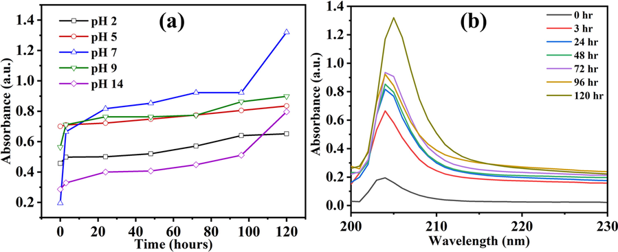
(a) BTA + LA + SB releasing profile in different pH values and (b) LHNT UV–vis spectra at pH 7.
4 Conclusion
Development and characterization of an efficient epoxy-based innovative coating system for corrosion protection of steel have been carried out by reinforcing halloysite nanotubes (HNTs) loaded with multicomponent inhibitor (BTA + LA + SB) into an epoxy matrix (LHNT COAT). The SEM micrographs represent a variation in the HNT particle sizes by showing a slightly puffed structure of the loaded HNT compared with the unloaded HNT with some particles inside the HNT lumen due to the inhibitor’s presence in the HNT. Moreover, the specific surface area of LHNT was 19.371 m2/g compared to the unloaded HNT, which was 115.319 m2/g indicating a high loading of the BTA + LA + SB inhibitor in the HNT. Furthermore, the charge transfer resistance at low frequency impedance spectra was 50 GΩ.cm2 after exposing LHNT COAT to 3.5 wt% NaCl solution for 15 days corresponds to a corrosion inhibition efficiency of 99.6% and 98.88% compared to the blank epoxy and unloaded HNT coating, respectively. The UV–vis analysis showed a good absorbance of LHNT in all the mediums (acidic, neutral, and alkaline) with a higher inhibitor release in the neutral media. The inhibition effect was due to the formation of some components resulting from the reaction of the primary inhibitor components such as benzoic acid, benzoic acid 2-oxododecyl ester, benzyl laurate, sodium laurate, dodecanone, or a combination of some of them as anticipated by the corrosion inhibition mechanism. The decent barrier properties of LHNT COAT make them suitable for numerous industrial applications.
Acknowledgements
This publication was made possible by NPRP Grant 11S–1226-170132 and NPRP 13S-0120-200116 from the Qatar National Research Fund (a member of the Qatar Foundation). Statements made herein are solely the responsibility of the authors. The authors would like to thank the Central laboratory Unit (CLU), Qatar University, for SEM and TEM analyses.
Declaration of Competing Interest
The authors declare that they have no known competing financial interests or personal relationships that could have appeared to influence the work reported in this paper.
References
- Experimental and theoretical investigations of benzoic acid derivatives as corrosion inhibitors for AISI 316 stainless steel in hydrochloric acid medium: DFT and Monte Carlo simulations on the Fe (110) surface. RSC Adv.. 2020;10:41137-41153.
- [CrossRef] [Google Scholar]
- Extracts of ruta chalepensis as green corrosion inhibitor for copper CDA 110 in 3% NaCl medium: experimental and theoretical studies. Anal. Bioanal. Electrochem.. 2019;11:830-850.
- [Google Scholar]
- Influence of pH and chloride concentration on the corrosion behavior of unalloyed copper in NaCl solution: a comparative study between the micro and macro scales. Materials (Basel). 2012;5:2439-2464.
- [CrossRef] [Google Scholar]
- Halloysite nanotubes loaded with imidazole dicarboxylic acid to enhance protection properties of a polymer coating. Prog. Org. Coat.. 2019;127:375-384.
- [CrossRef] [Google Scholar]
- Computer simulation of the corrosion inhibition of copper in acidic solution by alkyl esters of 5-carboxybenzotriazole. Corros. Sci.. 2003;45:81-96.
- [CrossRef] [Google Scholar]
- Comparison of different methods for measuring the passive film thickness on metals. Electrochim. Acta. 2016;201:340-347.
- [CrossRef] [Google Scholar]
- Sodium Benzoate, Natl. Cent. Biotechnol. Inf. (2022). https://pubchem.ncbi.nlm.nih.gov/source/hsdb/696
- The inhibition effects of benzoic acid and salicylic acid on the corrosion of steel in sulfuric acid medium. Mater. Chem. Phys. – Mater. Chem. Phys.. 2002;76:52-58.
- [CrossRef] [Google Scholar]
- Inhibition of steel corrosion by calcium benzoate adsorption in nitrate solutions. Corros. Sci.. 2005;47:369-383.
- [CrossRef] [Google Scholar]
- Cerium-loaded algae exoskeletons for active corrosion protection of coated AA2024-T3. Corros. Sci.. 2017;128:164-175.
- [CrossRef] [Google Scholar]
- Double-doped zeolites for corrosion protection of aluminium alloys. Micropor. Mesopor. Mater.. 2014;188:8-15.
- [CrossRef] [Google Scholar]
- Inhibition of copper corrosion by 1,2,3-benzotriazole: a review. Corros. Sci.. 2010;52:2737-2749.
- [CrossRef] [Google Scholar]
- Corrosion inhibition of iron in acidic solutions by monoalkyl phosphate esters with different chain lengths. Ind. Eng. Chem. Res.. 2015;54:1941-1952.
- [CrossRef] [Google Scholar]
- The application of benzimidazole and zinc cations intercalated sodium montmorillonite as smart ion exchange inhibiting pigments in the epoxy ester coating. Corros. Sci.. 2015;94:207-217.
- [CrossRef] [Google Scholar]
- S. Habib, A. Hassanein, R. Kahraman, E. Mahdi Ahmed, R.A. Shakoor, Self-healing behavior of epoxy-based double-layer nanocomposite coatings modified with Zirconia nanoparticles, Mater. Des. 207 (2021) 109839. https://doi.org/https://doi.org/10.1016/j.matdes.2021.109839.
- Layered double hydroxides as containers of inhibitors in organic coatings for corrosion protection of carbon steel. Prog. Org. Coat.. 2012;74:343-348.
- [CrossRef] [Google Scholar]
- Multilevel self-healing characteristics of smart polymeric composite coatings. ACS Appl. Mater. Interfaces. 2021;13:51459-51473.
- [CrossRef] [Google Scholar]
- pH-Responsive nanovalves based on encapsulated halloysite for the controlled release of a corrosion inhibitor in epoxy coating. RSC Adv.. 2015;5:90609-90620.
- [CrossRef] [Google Scholar]
- Determination of effective capacitance and film thickness from constant-phase-element parameters. Electrochim. Acta. 2010;55:6218-6227.
- [CrossRef] [Google Scholar]
- Nanocomposite organic coatings for corrosion protection of metals: a review of recent advances. Prog. Org. Coat.. 2022;162:106573
- [CrossRef] [Google Scholar]
- Self-healing performance of smart polymeric coatings modified with tung oil and linalyl acetate. Polymers (Basel). 2021;13
- [CrossRef] [Google Scholar]
- The electrochemical behavior of nanocomposite organic coating based on clay nanotubes filled with green corrosion inhibitor through a vacuum-assisted procedure. Compos. Part B Eng.. 2019;171:96-110.
- [CrossRef] [Google Scholar]
- ORMOSIL-epoxy coatings with ceramic containers for corrosion protection of magnesium alloys ZK10. Prog. Org. Coatings.. 2013;76:459-470.
- [CrossRef] [Google Scholar]
- Adsorption and inhibitive properties of Ruta chalepensis L. oil as a green inhibitor of steel in 1 M hydrochloric acid medium. Int. J. Electrochem. Sci.. 2014;9:3334-3348.
- [Google Scholar]
- Designing and performance evaluation of polyelectrolyte multilayered composite smart coatings. Prog. Org. Coat.. 2019;137:105319
- [CrossRef] [Google Scholar]
- Hybrid halloysite nanotubes as smart carriers for corrosion protection. ACS Appl. Mater. Interfaces. 2020;12:37571-37584.
- [CrossRef] [Google Scholar]
- Mechanical properties of HNT filled carbon fabric epoxy composites. Mater. Today Proc.. 2022;52:2048-2052.
- [CrossRef] [Google Scholar]
- Sodium benzoate, a D-amino acid oxidase inhibitor, added to clozapine for the treatment of schizophrenia: a randomized, double-blind, placebo-controlled trial. Biol. Psychiatry. 2018;84:422-432.
- [CrossRef] [Google Scholar]
- Why does vacuum drive to the loading of halloysite nanotubes? the key role of water confinement. J. Colloid Interface Sci.. 2019;547:361-369.
- [CrossRef] [Google Scholar]
- Halloysite nanotubes filled with salicylic acid and sodium diclofenac: effects of vacuum pumping on loading and release properties. J. Nanostruct. Chem.. 2021;11
- [CrossRef] [Google Scholar]
- Halloysite nanotubes filled with MgO for paper reinforcement and deacidification. Appl. Clay Sci.. 2021;213:106231
- [CrossRef] [Google Scholar]
- Hydroxypropyl cellulose films filled with halloysite nanotubes/wax hybrid microspheres. Ind. Eng. Chem. Res.. 2021;60:1656-1665.
- [CrossRef] [Google Scholar]
- Study of inhibition performance and adsorption behaviour of lauric acid on N80 steel in acidic and near neutral environments. Corros. Eng. Sci. Technol.. 2009;44:43-50.
- [CrossRef] [Google Scholar]
- M.H. Nazari, D. Bergner, X. Shi, Managing Metallic Corrosion on Winter Maintenance Equipment Assets, in: Environ. Sustain. Transp. Infrastruct., n.d.: pp. 61–76. https://doi.org/10.1061/9780784479285.006.
- Acid-modification and praseodymium loading of halloysite nanotubes as a corrosion inhibitor. Appl. Clay Sci.. 2020;184:105355
- [CrossRef] [Google Scholar]
- Active protective PEO coatings on AA2024: role of voltage on in-situ LDH growth. Mater. Des.. 2017;120:36-46.
- [CrossRef] [Google Scholar]
- Cellulose microfibers (CMFs) as a smart carrier for autonomous self-healing in epoxy coatings. New J. Chem.. 2020;44
- [CrossRef] [Google Scholar]
- Effectiveness of epoxy coating modified with yttrium oxide loaded with imidazole on the corrosion protection of steel. Nanomaterials. 2021;11:2291.
- [CrossRef] [Google Scholar]
- The application of anti-corrosion coating for preserving the value of equipment asset in chloride-laden environments: A review. Int. J. Electrochem. Sci.. 2015;10:10756-10780.
- [Google Scholar]
- Conducting polyaniline–nano-TiO2 composites for smart corrosion resistant coatings. Electrochim. Acta. 2009;54:1249-1254.
- [CrossRef] [Google Scholar]
- Efficacy and safety of add-on sodium benzoate, a D-amino acid oxidase inhibitor, in treatment of schizophrenia: a systematic review and meta-analysis. Asian J. Psychiatr.. 2022;68:102947
- [CrossRef] [Google Scholar]
- Combating food pathogens using sodium benzoate functionalized silver nanoparticles: synthesis, characterization and antimicrobial evaluation. J. Mater. Sci.. 2017;52
- [CrossRef] [Google Scholar]
- AEO7 surfactant as an eco-friendly corrosion inhibitor for carbon steel in HCl solution. Sci. Rep.. 2019;9:2319.
- [CrossRef] [Google Scholar]
- Inhibitive effect of sodium (E)-4-(4-nitrobenzylideneamino)benzoate on the corrosion of some metals in sodium chloride solution. Appl. Surf. Sci.. 2018;447:852-865.
- [CrossRef] [Google Scholar]
- The use of benzotriazole as a corrosion inhibitor for copper. Anti-Corros. Methods Mater.. 1970;17:9-15.
- [CrossRef] [Google Scholar]
- Anticorrosive reinforcement of waterborne epoxy coating on Q235 steel using NZ/BNNS nanocomposites. Prog. Org. Coat.. 2021;159:106410
- [CrossRef] [Google Scholar]
- Functionalization of h-BN by the exfoliation and modification of carbon dots for enhancing corrosion resistance of waterborne epoxy coating. Prog. Org. Coat.. 2022;165:106757
- [CrossRef] [Google Scholar]
- Preparation and corrosion behavior of Cu-8-HQ@HNTs/epoxy coating. Prog. Org. Coat.. 2019;139:105434
- [CrossRef] [Google Scholar]
- A self-healing polyurethane-based composite coating with high strength and anti-corrosion properties for metal protection. Compos. Part B Eng.. 2021;225:109273
- [CrossRef] [Google Scholar]
- Synthesis and adsorption properties of halloysite/carbon nanocomposites and halloysite-derived carbon nanotubes. Appl. Clay Sci.. 2016;119:284-293.
- [CrossRef] [Google Scholar]
- A study on corrosion behavior of micro-arc oxidation coatings doped with 2-aminobenzimidazole loaded halloysite nanotubes on AZ31 magnesium alloys. Surf. Coat. Technol.. 2021;416:127116
- [CrossRef] [Google Scholar]
- A novel acid-responsive HNTs-based corrosion inhibitor for protection of carbon steel. Colloids Surf. A Physicochem. Eng. Asp.. 2018;553:295-304.
- [CrossRef] [Google Scholar]
- Effect of inhibitor-loaded halloysite nanotubes on active corrosion protection of polybenzoxazine coatings on mild steel. Prog. Org. Coatings.. 2019;134:126-133.
- [CrossRef] [Google Scholar]
- Feasibility and corrosion inhibition efficacy of zeolite-supported lauric acid imidazoline as corrosion inhibitor in cementitious mortar. Constr. Build. Mater.. 2020;250:118861
- [CrossRef] [Google Scholar]
- Lauric acid is an inhibitor of clostridium difficile growth in vitro and reduces inflammation in a mouse infection model. Front. Microbiol.. 2018;8
- [CrossRef] [Google Scholar]
- Halloysite nanotubes as nanocontainer for smart coating application: a review. Prog. Org. Coatings.. 2017;111:175-185.
- [CrossRef] [Google Scholar]
- Corrosion of in-situ grown MgAl-LDH coating on aluminum alloy. Trans. Nonferrous Met. Soc. China.. 2015;25:3498-3504.
- [CrossRef] [Google Scholar]
- Construction of 3-aryl-1,2,4-benzotriazines via unprecedented rearrangement of bis(benzotriazol-1-yl)methylarenes. Tetrahedron Lett.. 2010;51:6763-6766.
- [CrossRef] [Google Scholar]
- Inhibition mechanism of sodium laurate to underdeposit corrosion of carbon steels in NaCl solutions. Corros. Eng. Sci. Technol.. 2010;45:442-448.
- [CrossRef] [Google Scholar]
- The effects of benzoic acid in chloride solutions on the corrosion of iron and aluminum. Turk. J. Chem.. 2002;26:403-408.
- [Google Scholar]
Appendix A
Supplementary material
Supplementary data to this article can be found online at https://doi.org/10.1016/j.arabjc.2022.104107.
Appendix A
Supplementary material
The following are the Supplementary data to this article:Supplementary data 1
Supplementary data 1


