

Translate this page into:
In situ flame-synthesis of nanostructured carbon materials via facile alcohol Bunsen burner
⁎Corresponding authors at: Green Energy Technology Research Center, Kun Shan University, Tainan 710, Taiwan, ROC. diago661228@stust.edu.tw (Hao-Lin Hsu), sshou@mail.ksu.edu.tw (Shuhn-Shyurng Hou)
-
Received: ,
Accepted: ,
This article was originally published by Elsevier and was migrated to Scientific Scholar after the change of Publisher.
Abstract
Carbon nanomaterials were synthesized in situ using a facile alcohol flame Lower flame temperatures were achieved with increasing amounts of aqueous ammonia Soot particles had concentrically stacked carbon layers with a diameter of 45 ± 5 nm Carbon nanotubes (CNTs) were grown via the root growth mechanism IG/ID ratios of CNOs (2.33) and CNTs (1.05) indicate good graphitic crystallization
Abstract
This study aimed to investigate the in-situ synthesis of nanostructured carbon materials using alcohol flames generated by a Bunsen lamp burner and a catalytic Ni substrate, as opposed to the chemical vapor deposition method. Four different liquid fuels were utilized, including n-butanol, ethanol, n-butanol/aqueous ammonia, and ethanol/aqueous ammonia. The carbon growth, morphology, and structure caused by the parameters of sampling position, temperature distribution, and liquid fuel type were investigated using the diffusion flame produced by the atmospheric alcohol lamp burner. The results show that the additive aqueous ammonia affects not only the flame temperature but also the axial position of the highest temperature. When using n-butanol and portions of 10 %, 20 %, and 30 % of aqueous ammonia mixed fuels, carbon nanotubes (CNTs), and carbon nano-onions (CNOs) are both observed; however, using ethanol and the portions of 10 %, 20 %, and 30 % of aqueous ammonia mixed fuels, only CNTs are synthesized. Soot particles show concentrically stacked carbon layers with a diameter of around 45 ± 5 nm. CNTs have no encapsulated Ni catalytic particles at the closed tip, showing the root growth mechanism and indicating differences from the top growth mechanism. In addition, graphene could be synthesized in pure n-butanol and n-butanol/ammonia flames, but not in pure ethanol and ethanol/ammonia flames. The IG/ID ratio values of the raw CNOs (2.33) and CNTs (1.05) are greater than 1, where IG/ID is the intensity ratio of Raman G-band and D-band peaks, indicating good crystallization of the graphite layer of these nanostructured carbon materials. Notably, flame synthesis via an alcohol Bunsen lamp burner simplifies operations saves resources, and improves conventional production, demonstrating a facile and efficient method.
Keywords
In-situ synthesis
Alcohol flame burner
Carbon nanotubes
Carbon nano-onions
Nanostructured

1 Introduction
Flame synthesis is a chemical synthesis that carries out reactions in a flame using a Bunsen burner or a flame torch. This synthesis method is widely used in various fields, including materials science, chemistry, and metallurgy, to prepare a variety of materials such as nanoparticles, ceramics, and metals. In recent decades, different dimensional carbon derivative nanomaterials have attracted worldwide attention in functional and practical fields, such as fullerene (Kroto et al., 1985) and soot onions (Chang et al., 2021; Vargas and Gülder, 2017; Mi et al., 2021; Hou et al., 2009), carbon nanotubes (CNTs) (Vander Wal et al., 2002; Memon et al., 2013; Unrau et al., 2010; How et al., 2022; Zhang et al., 2022; Hsu et al., 2021; Hsu et al., 2022), graphene (Hong et al., 2021; Gong et al., 2017; Tian et al., 2018; Wang et al., 2022; Li et al., 2022; Yun et al., 2022), graphene oxide (Down et al., 2018; Yeo et al., 2021; Zheng et al., 2022; Qiang et al., 2022; Liu et al., 2022) and carbon aerogel (Hsu et al., 2019). Modern research has reported that carbon-derivative materials present extraordinary performance in various potential applications, including supercapacitors (Wang et al., 2022; Li et al., 2022; Yun et al., 2022; Down et al., 2018; Yeo et al., 2021; Zheng et al., 2022; Qiang et al., 2022; Li et al., 2017; Zhang et al., 2022), biosensors (Bharath et al., 2015), and contamination removal (Hoai et al., 2017; Tian et al., 2020; Song et al., 2020).
Hydrocarbon flames provide a high temperature and carbon-enriched atmosphere to prepare nanostructured carbon materials successfully. The characteristic advantages of flame synthesis include: (a) part of the fuel provides heat, and the remaining one becomes a source to synthesize carbon materials. Therefore, another heating system is not required, which lowers apparatus and energy costs; (b) selecting various carbon sources is highly elastic for cost considerations; (c) continuous delivery of the heat and source from the flame is available for large-scale production.
In addition, several investigations have used diffusion flames of alcohols via the laboratory alcohol burner (Merchan-Merchan et al., 2010) and spirit lamp (Cheng et al., 2006; Pan and Bao, 2002; Pan et al., 2005). Helical carbon nanofibers as electrodes have been synthesized from an Sn-based metal–organic framework via an ethanol flame method in the atmospheric environment (Zhang et al., 2022). The vaporized carbon source subsequently diffuses to the substrates to form the eutectic metal intermediates to form CNTs by raising the temperature via an oxidizer burner. Afterward, the pyrolysis carbon source diffuses to deposit on the roots of the eutectic substrate particles, demonstrating the top growth of CNTs (Hsu et al., 2021; Lee and Park, 2000; Sinnott et al., 1999). The pyrolysis gas-phase carbon source continuously deposits and gradually pushes the eutectic catalyst particles upward to grow CNTs. Recently, published nanocrystalline diamonds (Manjarrez et al., 2022) and α-MoO3 nanoresonators (Yu et al., 2022) have also been synthesized using flame vapor deposition. The excellent quality phonon polaritonic van der Waals structures enable high-performance and low-loss platforms for infrared optical and optoelectronic applications. Besides, it shows the key parameters influencing the formation and yield of carbon nano-onions (CNOs) are both the oxygen and fuel concentrations of CNTs, and CNOs synthesized on a nickel substrate using counter-flow flames. The value of methane concentration for the onset of CNO formation decreased with increasing oxygen concentration or ethylene concentration (Hou et al., 2009). The double-flame structure was generated with a periodic flow of an ethylene-nitrogen mixture by using acoustic modulation to study carbon nanomaterial synthesis (Chung and Lin, 2011). In particular, from both numerical simulation and experimental data (Guo et al., 2021), the mass transfer in the synthesis process of nanoparticles using a swirling vortex flow reactor is controllable by enhancing ultrasound irradiation. Furthermore, a theory of negatively stretched premixed flames with inert/combustible sprays was developed using activation energy asymptotic analysis to explore the influence (Lin et al., 2003).
The objective of this study was to explore the in-situ synthesis of nanostructured carbon materials using alcohol flames generated by a Bunsen lamp burner, as opposed to the chemical vapor deposition method. The study employed four different liquid fuels, namely n-butanol, ethanol, n-butanol/25 % aqueous ammonia, and ethanol/25 % aqueous ammonia. Additionally, the study investigated the impact of adding 10 %, 20 %, and 30 % of 25 % aqueous ammonia to a mixture of n-butanol/25 % aqueous ammonia or ethanol/25 % aqueous ammonia on the flame appearance, flame height, and temperature effect associated with sampling position on the fabricated carbon nanomaterials. The study successfully investigated the carbon growth, morphology, and structure caused by the parameters of temperature effect, sampling position, and liquid blended fuels using the diffusion flame produced by the atmospheric alcohol Bunsen lamp burner. The n-butanol and ethanol were used due to the main differences in the C–H ratio, which dominate the flame appearance, heat source, and carbon sources, affecting the synthesis of nanostructured carbon materials. Therefore, pure and blended liquid fuels not only result in different flame appearances and flame heights but also affect temperature distribution, and in turn the growth of the carbon structure materials. Overall, flame synthesis via an alcohol Bunsen lamp burner simplifies operations, saves resources, and improves conventional production, demonstrating a fast and efficient method.
2 Experimental section
The experimental system considered in this study included an alcohol Bunsen lamp burner, observation of flame appearance, temperature measurement, metal substrate holding device, sampling system, and analysis of nanostructured carbon materials. Fig. 1 shows the schematic configuration of the alcohol Bunsen lamp burner used to synthesize carbon materials.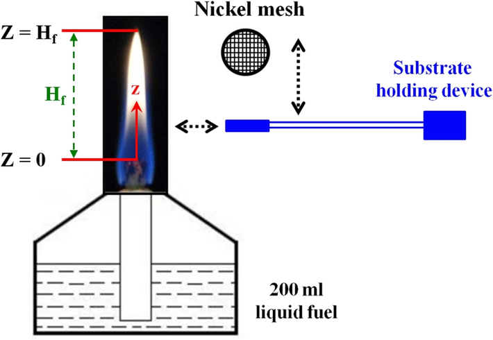
Schematic configuration of an alcohol burner with Ni sampling substrate.
2.1 Alcohol Bunsen lamp burner and liquid fuels
The glass alcohol Bunsen lamp burner for laboratory use has a total volume of 250 ml as shown in Fig. 1. A fixed 200 ml liquid fuel was added to the burner to retain the steady combustion flame condition. To avoid the different wick lengths affecting the flame pattern and sample collection results, the wick of the alcohol lamp is made of cotton thread with a diameter of about 6 mm. The total length of the cotton thread was 11 cm, which exposed 1 cm to the ceramic sleeve of the burner. The primary liquid fuel used in the experiment was n-butanol (SHOWA, 99.8 %) and ethanol (SHOWA, 95 %), and besides, further nitrogen-rich fuel was mixed with the 25 % aqueous ammonia in this study. Specifically, different proportions of 10 %, 20 %, and 30 % of 25 % aqueous ammonia were mixed with n-butanol or ethanol for the carbon nanomaterials forming under various flame conditions, respectively.
2.2 Observation of flame appearance, temperature measurement, and sample collecting
The study used a digital Nikon D70 camera with 6.1 million pixels CCD to record flame images and analyze photographs with the image software ImageJ (Schneider et al., 2012; Collins, 2007). Therefore, flame appearance could be observed and so did flame heights (Hf shown in Fig. 1). The gas temperature was measured and recorded along the central z-axis of the burner via the Pt/Pt-13 % Rh R-type thermocouple (0.05 mm in diameter). The thermocouple was installed in a three-dimensional positioner that allowed it to move horizontally and vertically with a 0.005 mm accuracy.
For carbon materials collection, a nascent nickel (Ni) grid around 200 meshes with a diameter of 3 mm and thickness of 0.2 mm was selected. The catalytic substrate Ni mesh grid was adopted as received without further purification and pretreatment. The nascent Ni grid was also installed in a three-dimensional positioner as the thermocouple, which allowed it to move horizontally and vertically with a 0.005 mm accuracy. During sampling collection, the Ni grid was extended into the area with the constant axial position (z) to be tested, waited for a sampling time of 2 min, and then taken out to collect the carbon material deposits on the substrate. In addition, the formation of carbon nanomaterials was highly influenced by the flame environmental atmosphere. Therefore, the effect of flame parameters (heat and carbon sources) on the synthesis of carbon materials was directly related to the sampling position.
2.3 Spectroscopy / microscopic investigations
The field-emission scanning electron microscope (FESEM, JEOL JSM-7000F) was used to observe the growth distribution, carbon structure, and surface morphology of the Ni grid substrate and carbon nanomaterials. Furthermore, high-resolution transmission electron microscopy (HRTEM, JEOL JEM-2100) was also used to monitor the morphological grid substrate and carbon nanomaterials. Raman spectrum was recorded to analyze by using the Tokyo Instruments spectrometer with a 632.8 nm He-Ne laser source. In particular, the characteristic disorder and graphitic peaks of CNTs were D-band (∼1350 cm−1) and G-band (∼1580 cm−1), respectively. In addition, the G’-band peak showed the overtone of the D band around 2700 cm−1 (Hsu et al., 2019).
3 Results and discussion
The study mixed different volume proportions of 0 %, 10 %, 20 %, and 30 % aqueous ammonia (25 % NH3/75 %H2O) with n-butanol (or ethanol) fuels in a total volume of 200 ml and labeled them as B100, B90N10, B80N20, and B70N30 (or E100, E90N10, E80N20, E70N30), respectively. Fig. 2 shows the variations in flame appearance over time of the alcohol Bunsen burner flames captured with a D70 camera during the combustion process of B100 and E100. Others are shown in Figure S1. It was observed that in all liquid fuel combustion flame patterns, the longest and shortest flame heights were observed at 5 and 255 min after igniting, respectively. Due to the capillary phenomenon to supply fuel, as initially ignited, the fuel supply rate through the wick of the Bunsen lamp burner is faster than the fuel burning rate, resulting in longer Hf naturally. After the burning time of 30 min, the fuel supply rate and burning rate reach a balance to stabilize gradually. As time goes by, the fuel in the Bunsen lamp burner gradually decreases, causing a lower flame height slowly. As the burning time increases, the fuel volume in the burner decreases, which shortens the capillary area of the wick that absorbs the liquid fuel. This results in a shorter Hf. For the flame patterns of B100, B90N10, B80N20, and B70N30, the flame color appears yellow and remains stable over time and ammonia portions. However, as the mixed aqueous ammonia increases, the blue color flame proportion at the flame root increases significantly. On the other hand, for the flame patterns of E100, E90N10, E80N20, and E70N30, the flame color appears orange-yellow with a blue color flame proportion at the root, and the flame changes to light brown with time. This shows that the blue color flame proportion increases progressively as the mixed aqueous ammonia increases.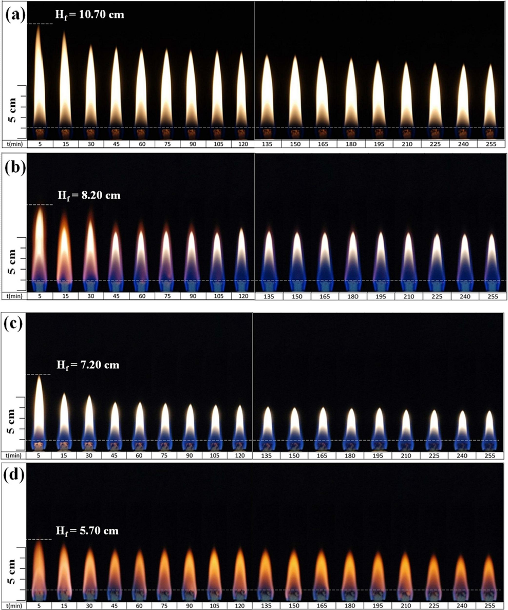
Flame appearance versus burning time using different fuels: (a) B100, (b) E100, (c) B70N30, and (d) E70N30 Bunsen lamp flames.
Fig. 3 illustrates the variations in flame height (Hf) over time for various liquid fuels. Here, z = 0 is defined as the axial coordinate of the highest position of the wick, and Hf is the flame height measured from z = 0, as shown in Fig. 1. When different concentrations of aqueous ammonia are added to n-butanol, Hf is significantly reduced. However, when pure ethanol and its mixtures with aqueous ammonia are used, Hf is only slightly reduced without any significant tendency to fluctuate. Notably, the change in Hf for all liquid fuels is more stable and less consumed during 45 to 90 min. Therefore, this period is considered the basis for sampling and collecting nanostructured carbon materials in this study.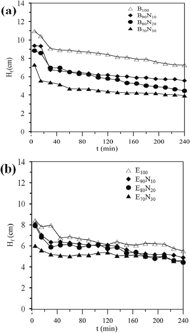
Variations in flame height (Hf) over burning time (t) for different liquid fuels.
Fig. 4 displays the axial temperature as a function of axial coordinate z for the n-butanol Bunsen lamp flame at 5, 30, 60, 90, 120, and 150 min. The recorded temperatures of other blended fuels (B90N10, B80N20, and B70N30) are presented in Figure S2. The axial temperature distributions of all fuels tend to be low on both sides and high in the middle, indicating a typical diffusion flame. The temperature fluctuation between z = 40 – 100 mm is significantly higher, which could be due to the flame’s longer length and slight external airflow causing it to flicker slightly. At 90 min and z = 48 mm, the highest flame temperature is recorded to be around 1400 °C. As time progressed, the corresponding position z with the highest flame temperature gradually decreased. Furthermore, the addition of aqueous ammonia not only affects the flame temperature but also the axial position (z) with the occurrence of the highest flame temperature. Figure S2 exhibits the same temperature trend as pure n-butanol and more proportional aqueous ammonia leads to a lower flame temperature. This shows the lower temperature at 1250 °C of z = 30 mm for B70N30 fuel.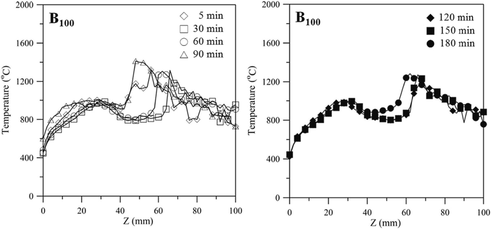
Axial temperature as a function of axial coordinate z for the n-butanol Bunsen lamp flame at 5, 30, 60, 90, 120, and 150 min.
Fig. 5 illustrates the axial temperature distribution as a function of axial coordinate z at 90 min for Bunsen lamp flames fueled by E100, E90N10, and E80N20 fuels. It can be seen from the figure that the temperature of E100 at z = 0 – 30 mm is lower than those of E90N10 and E80N20 liquid fuels. This is because in the range of z = 0 – 30 mm, the liquid E100 fuel leaves the wick and evaporates, and then the largest amount of vaporized fuel compared to E90N10 and E80N20 diffuses to the flame sheet and reacts with air, resulting in the highest flame temperature at about z = 4 mm. The flame with a lower flame height diffuses more heat to the vaporized fuel, causing a higher temperature in lower axial positions. This is why the temperature of E100 fuel at z = 0 – 30 mm is lower than those of E90N10 and E80N20 liquid fuels. Additionally, the ethanol concentration of E90N10 or E80N20 fuel is lower than that of E100 fuel due to more water in the aqueous ammonia. As the ethanol content in the ethanol/aqueous ammonia blended fuel decreases, more latent heat is required for water vaporization without contributing to combustion, while less vaporized fuel contributes to combustion. Therefore, decreased fuel vapor diffusion causes a lower flame temperature and a slightly lower temperature distribution before the flame sheet (z < 30 mm). For the E80N20 flame, the completed combustion condition takes place at z = 30 mm. Therefore, as z < 30 mm and increases from z = 0 mm, the temperature increases; however, after the highest temperature is achieved at z = 30 mm, with further increasing z value, the temperature decreases. This tendency shows a temperature distribution for diffusion flame. Similar characteristics are observed for the pure ethanol (E100) flame and E90N10 flame.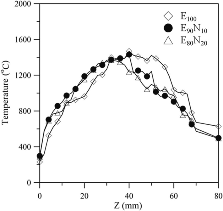
Axial temperature as a function of axial coordinate z for E100, E90N10, and E80N20 flames at a burning time of 90 min.
Fig. 6 shows the axial temperature as a function of an axial coordinate for E70N30 flames at 5, 30, 60, 90, 120, and 150 min. Compared to Fig. 5, the temperature distribution displays the same trend, while the highest temperature position moves to a lower range between 20 – 30 mm. The burning time of the E70N30 flame has less effect on the flame temperature. Moreover, the lower Hf of the E70N30 is less affected by the surrounding open-atmosphere airflow and is more stable for measuring the flame temperature. During 45 – 90 min, it shows less flame variation between z = 5 to 22 mm with the temperature around 480 – 1200 °C, which also meets the consideration for sampling and analysis of nanostructure carbon materials in this study. The Ni grid was extended into the inner zone (fuel side) of the conical flame for 45 – 90 min at z = 4 – 24 mm for 120 s to collect carbon material deposits from the substrate surface. Due to the feature structure of the diffusion flame, the sampling position is an important parameter that affects the carbon and heat sources in the synthesis process. The carbon source required for synthesis is obtained from fuel pyrolysis. In this study, the various liquid fuels and positions z are considered parameters affecting the formation of carbon nanomaterials. The surface morphology and overall structure of CNTs are observed using a FESEM and HRTEM.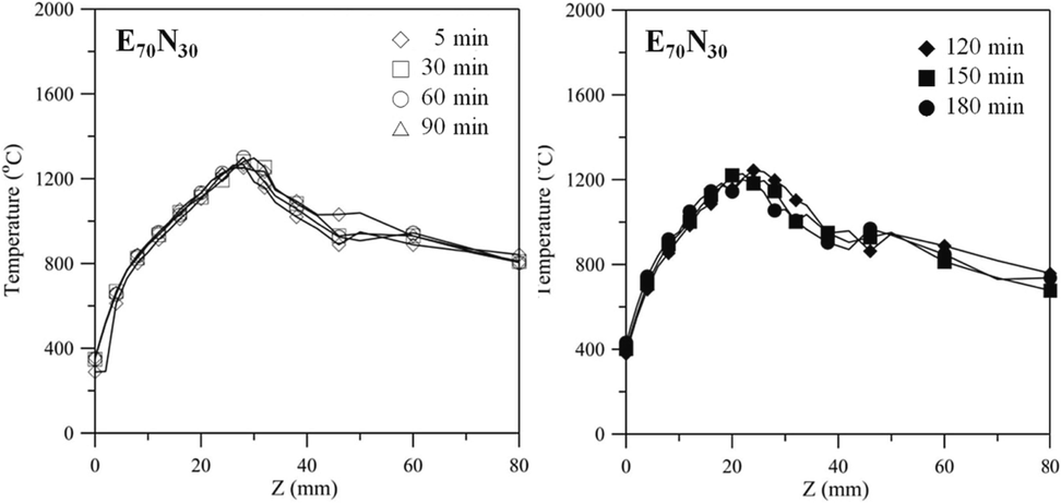
Axial temperature as a function of axial coordinate for E70N30 flames at 5, 30, 60, 90, 120, and 150 min.
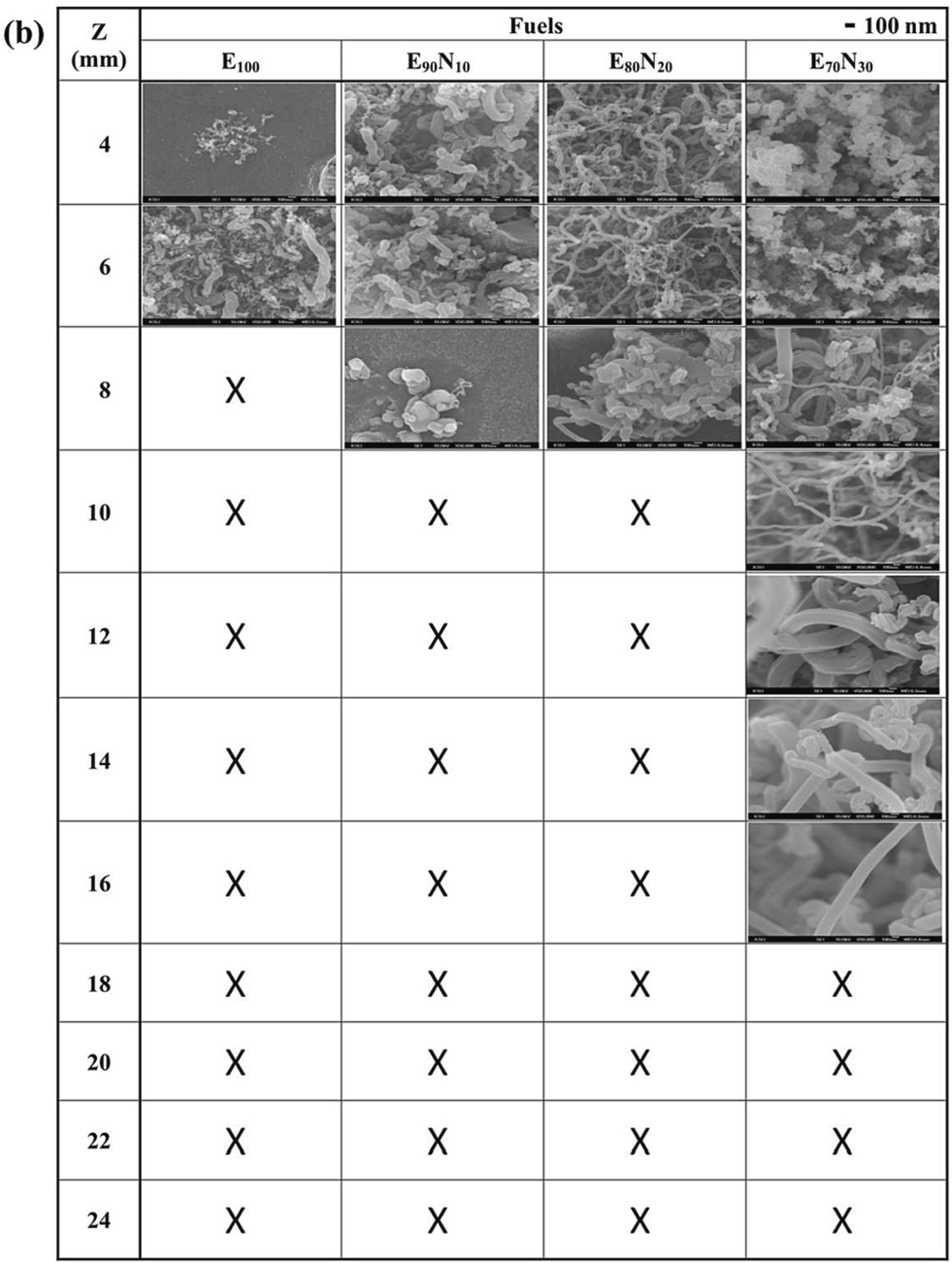
Fig. 7 displays the SEM top-view images of the as-synthesized nanostructured carbon materials at z = 4 – 24 mm for n-butanol, ethanol, and mixed fuels. The images include amorphous carbon soot, capsules, fibers, CNOs, and CNTs. When using B100, B90N10, B80N20, and B70N30 fuels, both CNTs and CNOs are observed. However, when using E100, E90N10, E80N20, and E70N30 fuels, only CNTs are synthesized. According to Figures 4 and S2, CNTs are usually synthesized at a lower sampling position z < 12 mm with 700 – 950 °C, which is close to the temperature range of the catalytic thermal chemical vapor deposition method (Hsu et al., 2021; Hsu et al., 2022). In particular, by adding aqueous ammonia to form B90N10, B80N20, and B70N30 fuels, carbon capsules and CNOs are synthesized at 10 – 22 mm. This indicates that the CNT growth rate was also affected by the additional ammonia in the gaseous carbon fuel source. At a high ammonia concentration, significant incorporation of nitrogen is probably doped into the CNT structure (Skudin et al., 2022). It is also proposed that there is competition between ammonia and hydrocarbon sources during the growth of CNTs (Lin et al., 2008). The interaction bonding synergism between ammonia and alcohol is supposed to improve the CNO decomposed temperature at higher temperatures of 1000 °C.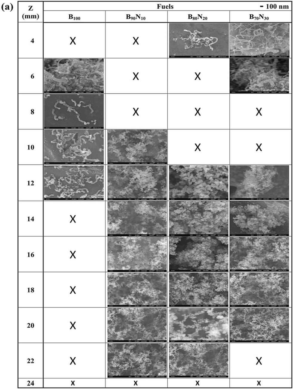
FESEM images of the synthesized nanostructured carbon materials at z = 4 – 24 mm for (a) n-butanol, (b) ethanol, and the mixed fuels.
FESEM images of the synthesized nanostructured carbon materials at z = 4 – 24 mm for (a) n-butanol, (b) ethanol, and the mixed fuels.
Fig. 8 shows the typical synthesized carbon soot, bamboo-like carbon fibers, CNOs, graphene, and CNTs. Soot particles are formed from carbon sources if oxygen is unavailable for complete combustion. Then a condensation nucleus of merely a few atoms of carbon occurs around them spherical, consisting of a few million carbon atoms with a diameter of about 10 – 100 nm (Lim et al., 2023; Pawlyta and Hercman, 2016; Serrano-Bayona et al., 2023; Xu et al., 2023). Numerous nuclei are visible inside the primary particles, and this matches that the soot was formed in a rapid vigorous process. Like the representative soot, the primary particles exhibit concentrically stacked carbon layers with a diameter of around 45 ± 5 nm. in Fig. 8a. However, carbon fiber exhibits a bamboo-like structure with a diameter of about 90 ± 10 nm without stacked layers. Fig. 8c and 8d show the hollow-center CNO with at least 20 graphene layers and the graphene, respectively. In the growth of CNOs, amorphous carbon is also accompanying outside CNOs. Fig. 8e and 8f present the base growth mechanism (Lee and Park, 2000) and the growth of CNTs. The pyrolysis carbon source of alcohol at a high temperature diffuses to deposit on the surface of the eutectic catalytic Ni grid, and hereafter, the root growth of CNTs proceeds to grow upwards. CNTs grow straight and have no encapsulated Ni catalytic particles at the closed tip, indicating which is different from the top growth mechanism. The gas-phase carbon source is continuously deposited and accumulates upward to form CNTs gradually. Once the formation of the graphite sheet starts, the diffusion of carbons probably accelerates into the catalytic reaction zone, resulting in the carbons being continuously added to the edge of the cap. As the CNT cap lifts off the catalytic Ni surface, the closed tip with the inside hollow is formed. We suppose the motive force departing from the catalytic particle could be the stress accumulated under the graphite cap. Table 1 summarizes the synthesized nanostructured carbon materials using alcohol Bunsen lamp flames ranging from z = 4 to 24 mm of all fuels. The darker color in the table indicates a higher content of carbon materials.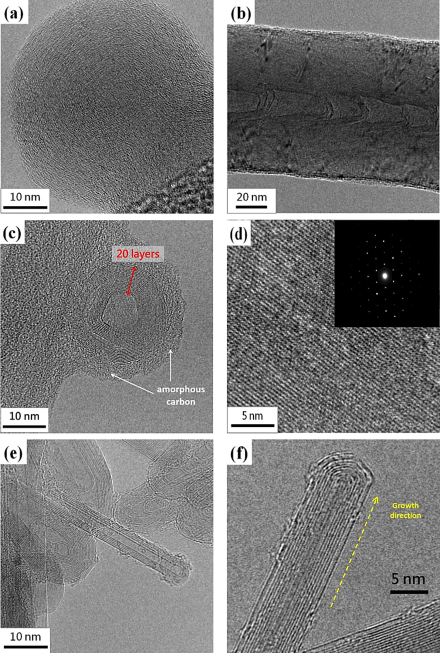
HRTEM images of synthesized (a) carbon soot, (b) bamboo-like carbon fibers, (c) CNOs, (d) graphene (the inset shows the diffraction pattern), and (e-f) CNTs.
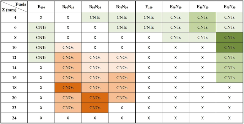
Table 2 summarizes the in-situ flame-synthesis results and compares them with other studies. Ethanol flame has traditionally been used for carbon nanomaterial synthesis. However, our results show that when using n-butanol and portions of 10 %, 20 %, and 30 % of aqueous ammonia mixed fuels, both CNTs and CNOs are observed. Conversely, when using ethanol and the portions of 10 %, 20 %, and 30 % of aqueous ammonia mixed fuels, only CNTs are synthesized. In addition, graphene could be synthesized in pure n-butanol and n-butanol/ammonia flames, but not in pure ethanol and ethanol/ammonia flames.
Carbon source
Flame type
Product
Reference
Corn oil
Flame deposition
Carbon nanoparticles
(Chang et al., 2021)
Methane
Diffusion flames
Soot
(Vargas and Gülder, 2017)
Methane and ethylene
Counterflow diffusion flame
Carbon nano-onions
(Hou et al., 2009)
Methane or ethylene
Counterflow diffusion flame
Carbon nanotubes and
few-layer graphene(Memon et al., 2013)
Ferrocene and tetraethylorthosilicate
Diffusion flame
Single-walled carbon nanotubes
(Unrau et al., 2010)
Methane
Diffusion flame
Copper-carbon nanotube composites
(How et al., 2022)
Methane
Counterflow burner
Hybrid nanowires
(Merchan-Merchan et al., 2010)
Ethanol
Combustion flame
Bamboo-like carbon nanotubes
(Cheng et al., 2006)
Ethanol
Diffusion flame
Carbon nanofiber
(Pan et al., 2005)
Methane
Atmospheric-pressure flame
Nanocrystalline diamonds
(Manjarrez et al., 2022)
Ethylene
Jet diffusion flame
Carbon nanostructures
(Chung and Lin, 2011)
n-Butanol, ethanol, and aqueous ammonia mixtures
Alcohol Bunsen burner flame
Nanostructured carbon materials
Present work
Fig. 9 shows the non-invasive Raman spectra of as-synthesized nanostructured materials, including CNOs using B90N10 fuel at 10 mm and CNTs using E70N30 fuel at 14 mm, respectively. The Raman spectra were obtained using a laser with a wavelength of 632.8 nm. The characteristic disorder and graphitic peaks of CNOs and CNTs are D-band (1350 cm−1) and G-band (1580 cm−1), respectively (Hsu et al., 2008; Lee and Park, 2000). Additionally, the peak named G’-band is the overtone of the D-band at 2700 cm−1. The relative intensity ratio of G-band to D-band, IG/ID, declares the quality of graphitization or defective disorders on carbon materials. In this study, the IG/ID ratio values of the raw CNOs (2.33) and CNTs (1.05) are higher than 1, indicating good crystallization of the graphite layer of these nanostructured carbon materials. However, some IG/ID values of other carbon soot and fibers are lower than 1.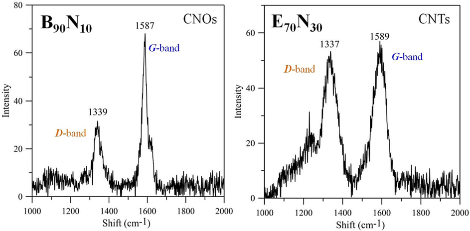
Raman spectra of (a) CNOs using B90N10 fuel at 10 mm and (b) CNTs using E70N30 one at 14 mm.
4 Conclusions
This research aims to develop in situ flame-synthesized carbon nanomaterials via an alcohol Bunsen burner instead of the chemical vapor deposition method. Using the diffusion flame produced by the atmospheric alcohol Bunsen lamp burner, we successfully investigated the carbon growth, morphology, and structure caused by the parameters of temperature distribution, sampling position, and liquid blended fuels. Due to the capillary phenomenon to supply fuel, as initially ignited, the fuel supply rate through the wick of the Bunsen lamp burner is faster than the fuel burning rate, resulting in longer Hf naturally. After the burning time of 30 min, the fuel supply rate and burning rate reach a balance to stabilize gradually. As time goes by, the fuel in the Bunsen lamp burner gradually decreases, causing a lower flame height slowly. Moreover, the addition of aqueous ammonia not only affects the flame temperature but also the axial position z where the highest temperature occurs. The proportion of aqueous ammonia in the n-butanol/aqueous ammonia or ethanol/aqueous ammonia mixture has a direct impact on the flame height and temperature. As the proportion of aqueous ammonia increases, the flame height decreases and the flame temperature lowers When B100, B90N10, B80N20, and B70N30 fuels are used, both CNTs and CNOs are observed. However, when E100, E90N10, E80N20, and E70N30 fuels are used, only CNTs are synthesized. The primary particles exhibit concentrically stacked carbon layers with a diameter of around 45 ± 5 nm. CNTs do not have any Ni catalytic particles encapsulated at the closed tip, indicating differences from the top growth mechanism and showing the root growth mechanism. Carbon nanostructures fabricated using Bunsen lamp flames for all fuels in the range z = 4 to 24 mm were successfully studied and summarized. The IG/ID ratio values of the raw CNOs (2.33) and CNTs (1.05) were greater than 1, indicating good crystallization of the graphite layer of these carbon materials. Notably, flame synthesis using an alcohol burner is a significant method that simplifies operations, conserves resources, and enhances conventional production, demonstrating an easy and efficient approach.
CRediT authorship contribution statement
Hao-Lin Hsu: Conceptualization, Methodology, Validation, Investigation, Writing – original draft, Writing – review & editing. Ta-Hui Lin: Resources, Data curation. Chao-Ming Huang: Resources, Investigation, Data curation. Wei-Cheng Chiu: Resources, Investigation, Data curation. Wen-Chang Huang: Resources, Data curation, Validation. Shuhn-Shyurng Hou: Data curation, Funding acquisition, Formal analysis, Investigation, Resources, Supervision.
Acknowledgments
Financial support from the National Science and Technology Council of Taiwan (MOST 111-2222-E-168-003, NSCT 103-2221-E-168-01-013 & 112-2221-E-168-007) and the Green Energy Technology Research Center from the Featured Areas Research Center Program within the framework of the Higher Education Sprout Project by the Ministry of Education are gratefully acknowledged and appreciated. The authors also acknowledge the use of EM000600 of NSTC 111-2731-M-006-001 belonging to the Core Facility Center of National Cheng Kung University.
Declaration of competing interest
The authors declare that they have no known competing financial interests or personal relationships that could have appeared to influence the work reported in this paper.
References
- Enzymatic electrochemical glucose biosensors by mesoporous 1D hydroxyapatite-on-2D reduced graphene oxide. J. Mater. Chem. B. 2015;3:1360-1370.
- [Google Scholar]
- Flame synthesis of carbon nanoparticles from corn oil as a highly effective cationic dye adsorbent. Chemosphere. 2021;282:131062
- [Google Scholar]
- Synthesis of bamboo-like carbon nanotubes by ethanol catalytic combustion technique. Trans. Nonferrous Met. Soc. China. 2006;16:s435-s437.
- [Google Scholar]
- Nitrogen dilution effect on flame synthesis of carbon nanostructures with acoustic modulation. J. Phys. Chem. C. 2011;115:16287-16294.
- [Google Scholar]
- Fabrication of graphene oxide supercapacitor devices. ACS Appl. Energy Mater.. 2018;1:707-714.
- [Google Scholar]
- Learning from nature: constructing high performance graphene-based nanocomposites. Mater. Today. 2017;20:210-219.
- [Google Scholar]
- Shear turbulence controllable synthesis of aggregated nano-particles using a swirling vortex flow reactor assisted by ultrasound irradiation. Chem. Eng. J.. 2021;405:126914
- [Google Scholar]
- Thermal reduction of graphene-oxide-coated cotton for oil and organic solvent removal. Mater. Sci. Eng. B. 2017;216:10-15.
- [Google Scholar]
- High-yield synthesis of carbon nano-onions in counterflow diffusion flames. Carbon. 2009;47:938-947.
- [Google Scholar]
- Synthesising copper-carbon nanotube composites through methane diffusion flame. Mater. Today: Proc.. 2022;66:2655-2659.
- [Google Scholar]
- The synthesis, characterization of oxidized multi-walled carbon nanotubes, and application to surface acoustic wave quartz crystal gas sensor. Mater. Chem. Phys.. 2008;109:148-155.
- [Google Scholar]
- Three-dimensional bundle-like multi-walled carbon nanotubes composite for supercapacitor electrode application. Mater. Today Chem.. 2021;22:100569
- [Google Scholar]
- Environmental-friendly three-dimensional carbon nanotubes grown by soil clay and graphene oxide nanosheets for energy storage. Mater. Today Chem.. 2022;23:100644
- [Google Scholar]
- Application of Graphene Oxide Aerogel to the Adsorption of Polycyclic Aromatic Hydrocarbons Emitted from the Diesel Vehicular Exhaust. J. Environ. Chem. Eng.. 2019;7:103414
- [Google Scholar]
- Growth model of bamboo-shaped carbon nanotubes by thermal chemical vapor deposition. Appl. Phys. Lett.. 2000;77:3397-3399.
- [Google Scholar]
- Metallic 1T'-MoTe2 Nanoparticle-Incorporated Graphene for Enhanced High Current Hydrogen Evolution and Supercapacitor Performance. ACS Appl. Energy Mater.. 2022;5:10680-10689.
- [Google Scholar]
- Boosting the specific surface area of hierarchical porous carbon aerogel by multiple roles of the catalyst towards high-performance supercapacitors. ChemElectroChem. 2017;4:3119-3125.
- [Google Scholar]
- A critical review of heterogeneous catalyst design for carbon nanotubes synthesis: Functionalities, performances, and prospects. Fuel Process. Technol.. 2023;241:107624
- [Google Scholar]
- A theoretical study on Bunsen spray flames. Int. J. Heat Mass Transf.. 2003;46:963-971.
- [Google Scholar]
- Effect of ammonia on the growth of carbon nanotubes. J Nanosci Nanotechnol.. 2008;8:2647-2650.
- [Google Scholar]
- High-energy-density asymmetric supercapacitor based on a nickel cobalt double hydroxide/reduced-graphene-oxide fiber electrode. ACS Appl. Energy Mater.. 2022;5:9605-9615.
- [Google Scholar]
- Atmospheric-Pressure Flame Vapor Deposition of Nanocrystalline Diamonds: Implications for Scalable and Cost-Effective Coatings. ACS Appl. Nano Mater.. 2022;5:10715-10723.
- [Google Scholar]
- Flame synthesis of carbon nanotubes and few-layer graphene on metal-oxide spinel powders. Carbon. 2013;63:478-486.
- [Google Scholar]
- Flame synthesis of hybrid nanowires with carbon shells and tungsten-oxide cores. Carbon. 2010;48:4510-4518.
- [Google Scholar]
- Near-threshold soot formation in premixed flames at elevated pressure. Carbon. 2021;181:143-154.
- [Google Scholar]
- Well-aligned carbon nanotubes from ethanol flame. J. Mater. Sci. Lett.. 2002;21:1927-1929.
- [Google Scholar]
- Novel solid-cored carbon nanofiber grown on steels substrates in ethanol flames. J. Mater. Sci.. 2005;40:1293-1295.
- [Google Scholar]
- Transmission electron microscopy (TEM) as a tool for identification of combustion products: Application to black layers in speleothems. Ann. Soc. Geol. Pol.. 2016;86:237-248.
- [Google Scholar]
- Layer-by-Layer Self-Assembled TEMPO-oxidized cellulose nanofiber/reduced graphene oxide/polypyrrole films for self-supporting flexible supercapacitor electrodes. ACS Appl. Nano Mater.. 2022;5:6305-6315.
- [Google Scholar]
- Flame Synthesis of Carbon and Metal-Oxide Nanoparticles: Flame Types. Effects of Combustion Parameters on Properties and Measurement Methods, Materials. 2023;16:1192.
- [Google Scholar]
- Model of carbon nanotube growth through chemical vapor deposition. Chem. Phys. Lett.. 1999;315:25-30.
- [Google Scholar]
- Carbon microtube aerogel derived from kapok fiber: an efficient and recyclable sorbent for oils and organic solvents. ACS Nano. 2020;14:595-602.
- [Google Scholar]
- Graphene quantum dots from chemistry to applications. Mater. Today Chem.. 2018;10:221-258.
- [Google Scholar]
- Amphiphilic Calcium Alginate Carbon Aerogels: Broad-Spectrum Adsorbents for Ionic and Solvent Dyes with Multiple Functions for Decolorized Oil−Water Separation. ACS Sustainable Chem. Eng.. 2020;8:12755-12767.
- [Google Scholar]
- Characterization of diffusion flames for synthesis of single-walled carbon nanotubes. Combust. Flame. 2010;157:1643-1648.
- [Google Scholar]
- Optimization of flame synthesis for carbon nanotubes using supported catalyst. J. Phys. Chem. B. 2002;106:13122-13132.
- [Google Scholar]
- Pressure dependence of primary soot particle size determined using thermophoretic sampling in laminar methane-air diffusion flames. Proc. Combust. Inst.. 2017;36:975-984.
- [Google Scholar]
- Spatial-Interleaving Graphene Supercapacitor with High Area Energy Density and Mechanical Flexibility. ACS Nano. 2022;16:12813-12821.
- [Google Scholar]
- Synergistic flame retardant effect of carbon nanohorns and ammonium polyphosphate as a novel flame retardant system for cotton fabrics. Chem. Eng. J.. 2023;451:138566
- [Google Scholar]
- Ultralong and millimeter-thick graphene oxide supercapacitors with high volumetric capacitance. ACS Appl. Energy Mater.. 2021;4:8059-8069.
- [Google Scholar]
- Ultrahigh-quality infrared polaritonic resonators based on bottom-up-synthesized van der Waals Nanoribbons. ACS Nano. 2022;16:3027-3035.
- [Google Scholar]
- Cyclodextrin/Graphene-Based Porous Carbon Nano fibers with Embedded MnO2 Nanoparticles for Supercapacitor Applications. ACS Appl. Nano Mater.. 2022;5:5688-5698.
- [Google Scholar]
- Facile yet versatile assembling of helical carbon nanofibers via metal-organic frameworks burned in ethanol flame and their electrochemical properties as electrode of supercapacitor. J. Power Sources. 2022;512:230908
- [Google Scholar]
- Experimental study of thiophene and ferrocene in synthesis of single-walled carbon nanotubes in rich premixed hydrogen/air flames. Combust. Flame. 2022;238:111939
- [Google Scholar]
- Layer-by-layer assembly of graphene oxide and polyethylenimine on carbon nanofiber films for supercapacitor applications. ACS Appl. Nano Mater.. 2022;5:455-463.
- [Google Scholar]
Appendix A
Supplementary material
Supplementary data to this article can be found online at https://doi.org/10.1016/j.arabjc.2024.105654.
Appendix A
Supplementary material
The following are the Supplementary data to this article:Supplementary data 1
Supplementary data 1


