

Translate this page into:
Surface engineering of Pt surfaces with Au and cobalt oxide nanostructures for enhanced formic acid electro-oxidation
⁎Corresponding authors. islam.ahmed@bue.edu.eg (Islam M. Al-Akraa), ammohammad@cu.edu.eg (Ahmad M. Mohammad)
-
Received: ,
Accepted: ,
This article was originally published by Elsevier and was migrated to Scientific Scholar after the change of Publisher.
Abstract
A novel n-CoOx/n-Au/n-Pt nanocatalyst assembled onto a glassy carbon (GC) substrate is recommended for efficient formic acid electro-oxidation (FAEO), the principal anodic reaction in the direct formic acid fuel cells (DFAFCs).
Abstract
A catalyst composed of Pt nanoparticles was engineered with Au and cobalt oxide nanostructures. It showed a promising catalytic performance toward the formic acid electro-oxidation. Adjusting its loading hierarchy drove the reaction mechanism to the desirable dehydrogenation pathway. Geometric and electronic enhancements were elucidated and quantified.
Abstract
This study aims to mitigate the CO poisoning of platinum (Pt) surfaces during formic acid electro-oxidation (FAEO), the essential anodic reaction in the direct formic acid fuel cells (DFAFCs). For this purpose, a glassy carbon (GC) electrode was amended sequentially with Pt (n-Pt), gold (n-Au), and cobalt oxide (n-CoOx) nanostructures. Fascinatingly, the ternary modified n-CoOx/n-Au/n-Pt/GC catalyst (for which n-Pt, n-Au, and n-CoOx were sequentially and respectively assembled onto the GC surface) exhibited a remarkable electrocatalytic enhancement toward FAEO, which surpassed ca. 53 times that of the Pt/GC catalyst. Additionally, it exhibited a much (ca. 18 times) higher stability after 3000 s of continuous electrolysis. The observed enhancement was proven to originate from driving the reaction mechanism principally to the desirable direct dehydrogenation pathway on the expense of the poisoning dehydration path. The impedance and CO stripping measurements confirmed the prevailing of both the electronic and third body effects in the catalytic enhancement.
Keywords
Poisoning
Formic acid
Cobalt oxide
Gold
Platinum
Fuel cells

1 Introduction
In 2015, at COP21 in Paris, for the first time ever, 192 countries plus the European Union agreed to reduce the global warming by 1.5 °C. In 2021, at COP26 in Glasgow, over 100 world leaders confirmed persisting the 1.5 °C commitment alive, finalising the outstanding elements of the Paris agreement (Government, 2021).
In fact, CO2 that is produced mostly from the traditional combustion of fossil fuels (coal, petroleum and natural gas) is the major greenhouse gas responsible for the global warming. To fulfil the abovementioned agreements and to meet the assigned environmental legislations, CO2 emissions should be extensively reduced. One of the best scenarios to achieve this goal proceeds by promoting renewable energy-based industries that encourage switching from fossil-based industries to clean renewable technologies (Al-Akraa et al., 2018; Al-Akraa et al., 2013, 2017; Al-Akraa et al., 2019c; Mohammad et al., 2003).
In this regard, fuel cells (FCs) appeared as a promising eco-friendly technology, particularly, for renewable energy plants in restoring excess electricity from saved hydrogen. Indeed, a FC can be viewed as an electrochemical engine that directly converts chemical energy into electricity (Al-Akraa et al., 2022a). Due to their static nature, FCs operate with no vibration (no noise) (Sharaf and Orhan, 2014; Wilberforce et al., 2016). Additionally, the simple assembly of FCs guarantees a broad range of applications in stationary and portable devices as well as in electric vehicles (Hassan, 2021).
FCs are classified depending on their operating temperatures, fuel and electrolyte. The well-known hydrogen FCs (HFCs), that operate at low temperatures and used H2 gas as a fuel and solid membranes as the electrolyte, could successfully turn the idea into real products such as Toyota Mirai, Honda Clarity, Mazda’s Hydrogen RX-8 RE and several other products. According to a report by Market research future (MRF), the HFCs vehicle market size was projected to worth USD 46.89 Billion by 2028, registering a compound annual growth rate (CAGR) of 68.52% during the forecast period (2021–2028), compared to USD 1.17 billion in 2020 (Future, 2021). However, H2 gas has very low density, i.e., 0.0813 g/L (at 25 °C and 1 bar) that turned its storage inconvenient (Lide, 2008). Todays, HFCs vehicles store on-board compressed hydrogen (700 bar) with comparable refuelling time (less than3 min) and driving range (≥500 km) to conventional gasoline-fuelled vehicles (Sloth, 2013). However, such a compression consumes an amount of energy comparable to 13–18% of the low heating value and the volumetric energy density becomes 5.6 MJ/L, which is far less than 32.0 MJ/L for gasoline (Jensen et al., 2007; Møller et al., 2017). All these complications with H2 necessitated a replacement with small organic hydrogen-containing liquid fuels that can be reformed to generate H2 onsite. Formic acid (FA), as one of them, was extremely recommended due to its small crossover flux through Nafion® membranes that allowed using ultrathin membranes and high concentrated fuel solutions in compact direct FA FCs (DFAFCs) (He et al., 2018; He et al., 2016; Rhee et al., 2003; Wang et al., 2004). Moreover, DFAFCs have a high theoretical cell potential (1.40 V vs. RHE) offering a higher voltage output than that of HFCs (1.23 V vs. RHE) (Demirci, 2007; Gong et al., 2018; Mohammad et al., 2018; Yu and Pickup, 2008). However, a catalytic deactivation of the Pt catalysts (that were mostly employed for FA electro-oxidation, FAEO, in DFAFCs) was endured because of the non-faradaic FA dissociation that typically accumulates poisonous (CO) species at the Pt surface (Al-Akraa and Mohammad, 2020; Al-Akraa et al., 2021; Al-Qodami et al., 2022; Bao et al., 2020; Bao et al., 2021; Bhalothia et al., 2020; Ferre-Vilaplana et al., 2017). Yet, Pt remained a better catalyst than Pd for FAEO because of its higher stability and better dissolution resistance in harsh reaction conditions (Al-Akraa et al., 2015; Yang et al., 2020). Mechanistically, several studies reported that FAEO takes place at Pt surfaces with a two-pathway mechanism (Al-Akraa et al., 2020; Al-Akraa et al., 2019a; Al-Akraa et al., 2011; Asal et al., 2019a; Asal et al., 2019b; Asal et al., 2022; El-Nagar and Mohammad, 2014; Jiang et al., 2019; Zhou et al., 2020). The dehydrogenation involves the direct oxidation of FA to CO2 (Eq. (1)) and the dehydration involving the adsorption of poisoning CO at the Pt surface (Eq. (2)). This adsorbed CO (COads) is further oxidized at high overpotentials (Eq. (3)).
Before commercializing DFAFCs, the CO poisoning should be overcome to retain their catalytic performance. This could partially be achieved by mitigating the CO adsorption via a third body effect (Busó-Rogero et al., 2014; Rettenmaier et al., 2020), or promoting its catalytic oxidation at low overpotentials (electronic or bifunctional effects) (Fang and Chen, 2021). Latest studies indicated a significant mitigation for CO poisoning by a Pt surface modification with a metal such as Pd (Al-Akraa et al., 2015; Maturost et al., (2021)a), Bi (Choi et al., 2019), Cu (Asal et al., 2022), and Au (Al-Akraa et al., (2019)b; Shi et al., 2020) or a metal oxide such as Ni oxide (El-Nagar et al., 2013), Mn oxide (Al-Akraa et al., 2022b; Asal et al., 2019a), and Cu oxide (Maturost et al., (2021)b). Nonetheless, up till now, inspections did not equip DFAFCs for a real marketing. In this investigation, a novel ternary catalyst composed of n-Pt, n-Au, and n-CoOx is suggested for a boosted FAEO in terms not only of activity but also of stability.
2 Experimental
2.1 Electrodes and reagents
A GC (d = 5.0 mm), an Ag/AgCl/KCl (sat), and a spiral Pt wire were all purchased from ALS, Japan and used as the working, reference, and counter electrodes, respectively.
All chemicals were of analytical grade and were used without further purification. Dihydrogen hexachloroplatinate (IV) hydrate (Premion®, H2PtCl6·xH2O, 99.9%, metals basis), hydrogen tetrachloroaurate (III) trihydrate (HAuCl4·3H2O, 99.99% metals basis, Au 49.0%), Cobalt (II) chloride hexahydrate (CoCl2·6H2O, 98%), sodium hydroxide-pellets (NaOH), sodium sulfate anhydrous (Na2SO4), and FA (HCOOH, 98%) were purchased from Alfa Aesar while sulfuric acid (AR, H2SO4, 98%) was purchased from Sigma Aldrich.
2.2 Catalyst's assembly
The proposed ternary catalyst was fabricated sequentially in three steps onto a GC electrode (cleaned as previously reported (El-Deab et al., 2015)). First, the electrodeposition of n-Pt was carried out from 0.1 M Na2SO4 aqueous solution containing 2.0 mM H2PtCl6·xH2O at 0.1 V for 300 s. The equivalent Pt film thickness was ca. 43 nm (Al-Akraa et al., 2015). Next, the electrodeposition of n-Au was carried out from 0.1 M Na2SO4 aqueous solution containing 2.0 mM HAuCl4·3H2O at 0.1 V for 350 s. The last step was the electrodeposition of n-CoOx that was carried out from 0.1 M phosphate buffer solution (PBS) aqueous solution containing 2.0 mM CoCl2·6H2O by cycling the potential from 1.2 to − 1.1 V for 10 cycles at 50 mVs−1.
The current study aims to compare the electrocatalytic performance toward FAEO of a set of three catalysts; GC modified with n-Pt (abbreviated as n-Pt/GC), n-Pt/GC modified with n-Au (abbreviated as n-Au/n-Pt/GC), and n-Au/n-Pt/GC modified with n-CoOx (abbreviated as n-CoOx/n-Au/n-Pt/GC).
2.3 Electrochemical measurements
All electrochemical measurements were conducted in a conventional two-compartment three-electrode glass cell at room temperature (ca. 25 ± 1 °C) using a Bio-Logic SAS Potentiostat (model SP-150) operated with EC-Lab software. Highly acidic solutions that can dissolve n-CoOx were avoided in all measurements. Currents were always normalized to the Pt surface area using a reference value of 420 μC cm−2 (Binningerz et al., 2014). The electrocatalytic performance of the proposed catalysts toward FAEO was conducted in 0.3 M FA (pH = 3.5) aqueous solution. The pH was adjusted by adding a suitable amount of NaOH. At this pH, the FA ionization into formate supported the improvement of the ionic conductivity of the electrolyte and the decrease of both the diffusion layer thickness and the polarization resistance (Abdullah et al., 2009).
2.4 Materials characterization
The surface morphology and composition of the proposed catalysts were assessed using a field-emission scanning electron microscope (FE-SEM, Quattro S, Thermo Fisher Scientific USA, magnification range from 6 to 2500000x and accelerating voltage from 200 V to 30 kV) combined with an energy dispersive X-ray spectrometer (EDXS, AMETEK USA Element Detector). The crystal structure of the proposed catalysts was inspected using a high-resolution X-ray diffractometer (XRD − PANalytical X’Pert Pro powder) that operated with a Cu anode, wavelength 0.154 nm, maximum 2.2 kW, and 60 kV.
3 Results and discussions
3.1 Electrochemical characterization
Electrochemical methods have long been serving as precise tools in the evaluation of the exact compositions of catalysts' surfaces. Fig. 1 displays the CVs of three proposed catalysts in 0.1 M NaOH at 100 mV s−1. The characteristic performance (Pt oxidation, Pt/PtO over a large anodic potential window accompanied by a subsequent PtO/Pt reduction at ca. − 0.35 V and the hydrogen adsorption/desorption (Hads/des) between −0.5 and −0.9 V) of a clean polycrystalline Pt electrode in basic media was observed in Fig. 1 for all the proposed catalysts (El-Nagar and Mohammad, 2014). By the modification with n-Au (n-Au/n-Pt/GC catalyst), the intensities of PtO/Pt reduction and Hads/des peaks decreased and a new reduction peak was observed at ca. 0.15 V that was assigned for the Au oxide reduction (Mohammad et al., 2018). The peak of Au oxide formation was overlapped with the Pt → PtO peak. By a subsequent modification with n-CoOx (n-CoOx/n-Au/n-Pt/GC catalyst), a continuous decrease was observed in the intensities of the PtO/Pt reduction and Hads/des peaks with the appearance of two new anodic peaks at ca. 0.3 and 0.6 and a reduction peak at ca. 0.5 V. These peaks corresponded to the sequential transformation of n-CoOx from lower to higher oxidation states (e.g., cobalt hydroxide, Co(OH)2, cobalt oxyhydroxide, CoOOH, and cobalt dioxide, CoO2) (El-Deab et al., 2015). It is important to mention here that the appearance of the Pt characteristic peaks in the n-Au/n-Pt/GC and n-CoOx/n-Au/n-Pt/GC catalysts beside the appearance of the Au characteristic peaks in the CoOx/n-Au/n-Pt/GC catalyst confirmed the partial deposition of n-Au and n-CoOx, respectively, onto the n-Pt/GC and n-Au/n-Pt/GC catalysts. In this regard, we have estimated the real surface area of n-Pt (the active component for FAEO, Ar) from the charge associated with the PtO reduction peak (see Table 1) employing a reference value of 420 μC cm−2 (Binningerz et al., 2014). The decrease in the Ar by the modification with n-Au and n-CoOx refered to the partial deposition onto the Pt surface. The surface coverages (Γ = 1 – (Ar(modified) – Ar(bare)) of n-Pt in the n-Au/n-Pt/GC and n-CoOx/n-Au/n-Pt/GC modified catalysts were estimated to be ≈ 66 and 77 %, respectively.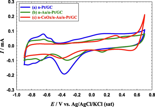
CVs obtained at the (a) n-Pt/GC, (b) n-Au/n-Pt/GC, and (c) n-CoOx/n-Au/n-Pt/GC catalysts in 0.1 M NaOH. Potential scan rate: 100 mV s- 1.
Catalyst
Ar (cm2)
n-Pt/GC
0.65
n-Au/n-Pt/GC
0.28
n-CoOx/n-Au/n-Pt/GC
0.15
3.2 Materials characterization
Morphologically, Fig. 2 shows the FE-SEM and the corresponding particle size distributions (adopted by ImageJ software) for n-Pt/GC (image A and B, respectively), n-Au/n-Pt/GC (images C and D, respectively), and n-CoOx/n-Au/n-Pt/GC (images E and F, respectively) catalysts. The n-Pt appeared spherical with ca. 175 nm average particle size (image A). The n-Au in the n-Au/n-Pt/GC catalyst retained the same spherical shape and the catalyst acquired some aggregates that homogeneously covered a large portion of the GC surface (image C). On the other hand, n-CoOx was deposited onto the n-Au/n-Pt/GC catalyst (image E) in a flower shape that scattered all the entire surface of n-Au and n-Pt. Figure S1 shows a SEM image with a lower magnification (5,000x) to obviously depict the distribution of these flowers. Analysis of the FE-SEM imaging of n-CoOx/n-Au/n-Pt/GC catalyst in view of the data interpretation of Fig. 1c confirmed the partial deposition of n-CoOx onto both of n-Pt and n-Au. This exposed all catalyst’s components (n-Pt, n-Au, n-CoOx) to the electrolyte.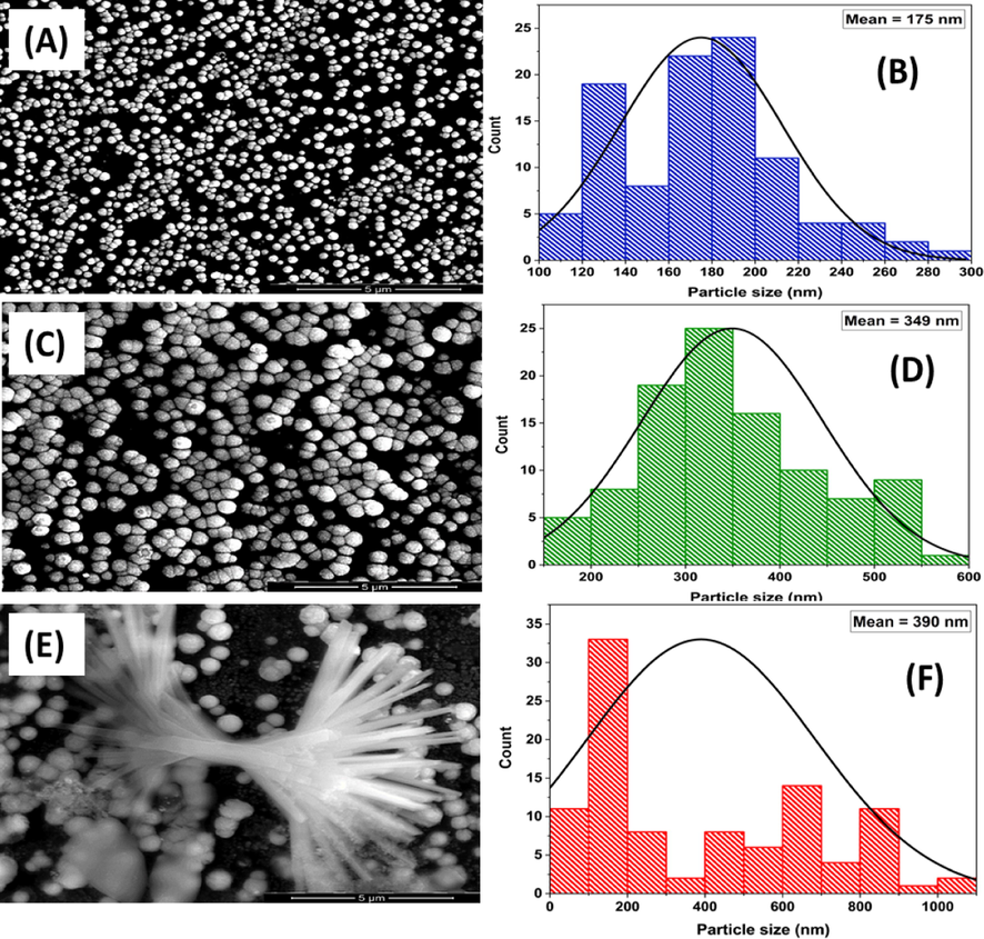
FE-SEM images (A, C, E) and particle size distribution (B, D, F) of the n-Pt/GC, n-Au/n-Pt/GC, and n-CoOx/n-Au/n-Pt/GC catalysts, respectively.
Fig. 3 shows the EDXS analyses of all proposed, which confirmed the successful assembly of all catalyst’s components and from which their percent compositions were calculated (see Table 2). An increase in the oxygen percentage and a decrease in Pt and Au percentages were noticed in the n-CoOx/n-Au/n-Pt/GC catalyst which agreed with the successful deposition of n-CoOx and the above-mentioned expectations.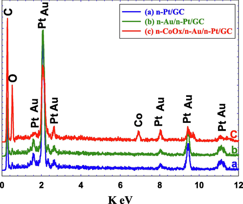
EDXS analysis of the (a) n-Pt/GC, (b) n-Au/n-Pt/GC, and (c) n-CoOx/n-Au/n-Pt/GC catalysts.
Catalyst
Element
Weight %
n-Pt/GC
C K
45.24
O K
3.63
Pt L
51.13
n-Au/n-Pt/GC
C K
39.77
O K
1.22
Pt L
48.73
Au K
10.28
n-CoOx/n-Au/n-Pt/GC
C K
47.64
O K
23.72
Pt L
17.09
Au K
9.35
Co K
2.21
Moreover, the XRD pattern in Fig. 4 confirmed the deposition of n-Pt in all the proposed catalysts in a face-centered cubic (fcc) structure, where the all diffraction peaks of Pt (1 1 1), (2 0 0), (2 2 0), and (3 1 1) appeared respectively at 38.5, 44.5, 65, and 78.5° (JCPDS card No. 96-101-1112) (Asal et al., 2019b; Kahler, 1921). Obviously, no peaks were noticed for n-Au in the n-Au/n-Pt/GC and the n-CoOx/n-Au/n-Pt/GC catalysts which might correlate the minute amount of n-Au at the catalyst's surface (Mohammad et al., 2018). However, interestingly, a new diffraction peak was observed at 19.5° for the n-CoOx/n-Au/n-Pt/GC catalyst (see inset of Fig. 4) corresponding to the (1 1 1) phase of the spinel Co3O4 (JCPDS card No. 43-1003) (Nugroho and Kim, 2014). Two other peaks appeared at ca. 25 and 43.3° were assigned to the (0 0 2) and (1 0 0) planes of the hexagonal carbon structure (JCPDS card No. 075-1621) (Keller et al., 2004).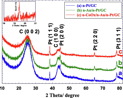
XRD analyses of the (a) n-Pt/GC, (b) n-Au/n-Pt/GC, and (c) n-CoOx/n-Au/n-Pt/GC catalysts. Inset shows a magnification for Fig. 4c between 19 and 20° with the Co (1 1 1) peak obviously seen.
3.3 FAEO: Activity and stability studies
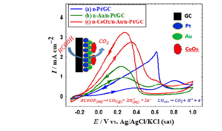
Formic acid electro-oxidation on Pt surfaces has been known to proceed via a dual-pathway mechanism (Shao, 2013; Wen et al., 2021). During the dehydrogenation, i.e., the direct pathway, FA is directly oxidized to CO2 and that can likely happen at non-hydroxylated Pt surfaces. The first oxidation peak (PI) that is observed between 0.3 and 0.4 V at all proposed catalysts (Fig. 5 a-c) belonged to this pathway. Simultaneously, FA is dissociated “non-faradaically” at low overpotentials to release the poisonous CO specious that gets adsorbed onto the Pt surface (COads); blocking intensively most of its active sites. This is the second pathway, the dehydration, or indirect pathway which continues to oxidize COads to CO2 at high overpotentials after hydroxylating the Pt surface at ca. 0.5 V. The second oxidation peak (PII) observed between 0.7 and 0.8 V at all the proposed catalysts (Fig. 5 a-c) was assigned to this indirect oxidation. On the reverse potential scan, the Pt active sites that were poisoned with COads free to participate effectively in FAEO and the oxidation current increased again (third oxidation peak, PIII). Figure S2 shows the Pt mass normalized activity toward FAEO.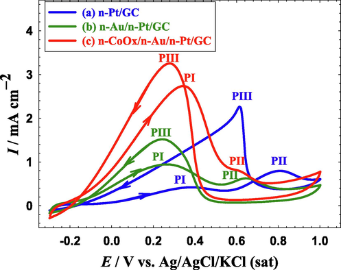
CVs obtained at the (a) n-Pt/GC, (b) n-Au/n-Pt/GC, and (c) n-CoOx/n-Au/n-Pt/GC catalysts in 0.3 M FA (pH = 3.5). Potential scan rate: 100 mVs−1.
In this regard, the ratios of PI:PII and PI:PIII are often used to identify the selectivity of FAEO pathways. The higher ratios mean, respectively, steering the FAEO mechanism to the direct pathway and a lower poisoning level with CO. Additionally, the onset potential (Eonset) value can reflect the catalyst capability to reduce the unrequired overpotentials (mainly of charge transfer) that diminishes the voltage output of the cell. Herein, the PI:PII, and PI:PIII ratios of the n-Pt/GC catalyst (Fig. 5a) were respectively ca. 0.9 and 0.22 (see Table 3), which were far away to move the DFAFCs into a real commercialization. These values changed after the modification with n-Au (n-Au/n-Pt/GC catalyst, Fig. 5b) for which the PI:PII, and PI:PIII ratios were 5.38 and 0.65, respectively. Fascinatingly after the further modification with n-CoOx, the n-Cox/n-Au/n-Pt catalyst (Fig. 5c) acquired the highest PI:PII, and PI:PIII ratios (48 and 0.8, respectively) and the lowest Eonset (−0.15 V) compared to 0.12 and − 0.09 V obtained, respectively, at the n-Pt/GC and n-Au/n-Pt/GC catalysts.
Catalyst
PI:PII
PI:PIII
Eonset/V
n-Pt/GC
0.9
0.22
0.12
n-Au/n-Pt/GC
5.38
0.65
−0.09
n-CoOx/n-Au/n-Pt/GC
48
0.8
−0.15
Furthermore, the stabilities of the proposed catalysts were inspected by chronoamperometric measurements. Fig. 6 displays the current transients (i-t curves) of the three proposed catalysts in 0.3 M FA (pH = 3.5) at 0.2 V for 3000 s. As seen in Fig. 6a, the current density of the n-Pt/GC catalyst decreased rapidly because of Pt poisoning with COads. This decay decreased greatly (Fig. 6b) after the modification with n-Au; matching the enhancement observed in Fig. 5b. Interestingly as the n-CoOx/n-Au/n-Pt/GC catalyst acquired the highest activity (Fig. 5c), it also retained the highest stability as seen in Fig. 6c. This is an additional value for the proposed modification in improving the catalytic tolerance against CO poisoning during FAEO.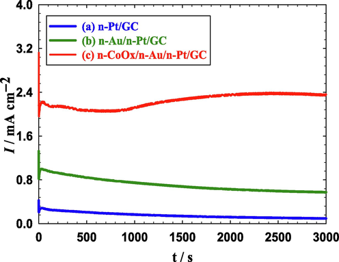
Current transients obtained at the (a) n-Pt/GC, (b) n-Au/n-Pt/GC, and (c) n-CoOx/n-Au/n-Pt/GC catalysts in 0.3 M FA (pH = 3.5) at 0.20 V.
3.4 FAEO: Mechanisms of enhancement
Electrochemical impedance spectroscopy (EIS) is a very good technique that can reflect the catalytic enhancement in terms of the charge transfer resistance (Rct) during FAEO. Fig. 7 displays the Nyquist plots for the three proposed catalysts measured in FA solution at an AC potential amplitude of 0.2 V and a frequency range from 10 mHz to 100 kHz. The data fitting was carried out using the EC-Lab software and the equivalent circuit of this system was displayed in the inset of Fig. 7. Over there, Rs and Cdl referred to the solution resistance and double layer capacitance, respectively, of the electrochemical system. Fig. 7c shows that the Rct of the n-CoOx/n-Au/n-Pt/GC catalyst (1.33 kΩ) was lower than that of the n-Au/n-Pt/GC (1.65 kΩ, Fig. 7b), and the n-Pt/GC (1.79 kΩ, Fig. 7a) catalysts; indicating an improved electron transfer process (Jiang et al., 2021). This again confirmed the superiority of the n-CoOx/n-Au/n-Pt/GC catalyst in terms of its higher catalytic activity than those of the other prepared n-Pt/GC and n-Au/n-Pt/GC catalysts.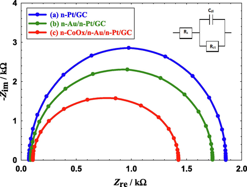
Nyquist plots obtained in 0.3 M FA (pH = 3.5) recorded at AC potential amplitude of 0.20 V for (a) n-Pt/GC, (b) n-Au/n-Pt/GC, and (c) n-CoOx/n-Au/n-Pt/GC catalysts in 0.3 M FA (pH = 3.5). Frequency range from 10 mHz to 100 kHz.
Additionally, the distinctive architecture, that may weaken the adsorption of CO poisoning intermediates, of the n-CoOx/n-Au/n-Pt/GC catalyst could be the reason behind the observed enhancement in the catalytic performance. Herein, CO was chemisorbed from 0.5 M FA on the three proposed catalysts at open circuit potential for 10 min. The adsorbed CO layer was then electrochemically stripped in 0.5 M Na2SO4 (pH = 3.5), as shown in the linear sweep voltammetry (LSV) of Fig. 8. Fig. 8a reveals that the adsorption of CO on the n-Pt/GC catalyst surface was much easier compared to that on the n-Au/n-Pt/GC (Fig. 8b) and n-CoOx/n-Au/n-Pt/GC (Fig. 8c) catalysts. The intensity and charge associated with the CO oxidation peak appeared around 0.7 V reflected that the resistance to CO poisoning was in the order of n-CoOx/n-Au/n-Pt/GC > n-Au/n-Pt/GC > n-Pt/GC. In another good point, the n-CoOx/n-Au/n-Pt/GC catalyst exhibited a more negative onset (by ca. 200 mV) and peak (by ca. 50 mV) potentials than the n-Pt/GC and n-Au/n-Pt/GC catalysts. This indicated that the surface engineered structure of the n-CoOx/n-Au/n-Pt/GC catalyst could effectively promote the charge transfer and mass transport for a faster electrode kinetics (Jiang et al., 2021). Furthermore, the LSV of CO stripping was repeated and the second cycle was compared to the first in Fig. S3. Interestingly, a single sweep was enough to ensure a complete oxidative removal of CO at the n-CoOx/n-Au/n-Pt/GC catalyst, in contrast to other catalysts. This again supported the superiority of the n-CoOx/n-Au/n-Pt/GC catalyst for FAEO.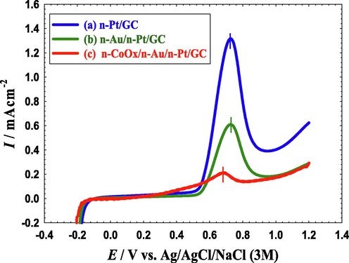
LSVs for oxidative CO stripping obtained at the (a) n-Pt/GC, (b) n-Au/n-Pt/GC, and (c) n-CoOx/n-Au/n-Pt/GC catalysts in 0.5 M Na2SO4 (pH = 3.5). Potential scan rate: 100 mVs−1. Before measurements, CO was adsorbed from 0.5 M FA at the open circuit potential for 10 min.
4 Conclusion
A simple effective electrochemical approach was applied for the fabrication of a ternary- modified CoOx/Au/Pt catalyst for FAEO. The multilayer structure of the catalyst was confirmed by several electrochemical and material characterization tools. Compared to the n-Pt/GC and n-Au/n-Pt/GC catalysts, the n-CoOx/n-Au/n-Pt/GC catalyst exhibited a better catalytic performance in terms of the activity (up to 48 times), long-term stability, and CO-tolerance during FAEO. The presence of nano-Au and n-CoOx in the catalyst succeeded not only to activate the geometrical influence by minimizing the CO adsorption but also to improve the electronic properties of the Pt surface that minimized the charge transfer resistance and boosted the FAEO reaction kinetics.
Declaration of Competing Interest
The authors declare that they have no known competing financial interests or personal relationships that could have appeared to influence the work reported in this paper.
References
- Effect of load, temperature and humidity on the pH of the water drained out from H2/air polymer electrolyte membrane fuel cells. J. Power Sources.. 2009;190:264-270.
- [CrossRef] [Google Scholar]
- Tuning the activity and stability of platinum nanoparticles toward the catalysis of the formic acid electrooxidation. Int. J. Electrochem. Sci.. 2020;15:5597-5608.
- [CrossRef] [Google Scholar]
- A simple and effective way to overcome carbon monoxide poisoning of platinum surfaces in direct formic acid fuel cells. Int. J. Electrochem. Sci.. 2019;14:8267-8275.
- [CrossRef] [Google Scholar]
- Effect of Palladium Loading on Catalytic Properties of Pd/GCE for the Electro-oxidation of Methanol, Formic Acid, and Ethylene Glycol. . Int. J. Electrochem. Sci.. 2022;17 Article Number: 220455
- [CrossRef] [Google Scholar]
- Assembling of NiOx/MWCNTs-GC anodic nanocatalyst for water electrolysis applications. Int. J. Electrochem. Sci.. 2018;13:9712-9720.
- [CrossRef] [Google Scholar]
- Facile synthesis of a tailored-designed AU/PT nanoanode for enhanced formic acid, methanol, and ethylene glycol electrooxidation. J. Nanomater. Article ID 2019:2784708.
- [CrossRef] [Google Scholar]
- A Competent MWCNT-Grafted MnOx/Pt Nanoanode for the Direct Formic Acid Fuel Cells. J. Chem.. 2022;2022 Article ID 3762138
- [CrossRef] [Google Scholar]
- A spin-coated TiOx/Pt nanolayered anodic catalyst for the direct formic acid fuel cells. Arab J Chem.. 2020;13:4703-4711.
- [CrossRef] [Google Scholar]
- Electrooxidation of Formic Acid at Platinum-Gold Nanoparticle-modified Electrodes. Chem. Lett.. 2011;40:1374-1375.
- [CrossRef] [Google Scholar]
- Self-assembling of gold nanoparticles array for electro-sensing applications. Int. J. Electrochem. Sci.. 2013;8:458-466.
- [Google Scholar]
- Electrocatalysis by design: Synergistic catalytic enhancement of formic acid electro-oxidation at core-shell Pd/Pt nanocatalysts. Int. J. Hydrog. Energy.. 2015;40:1789-1794.
- [CrossRef] [Google Scholar]
- Flower-shaped gold nanoparticles: Preparation, characterization, and electrocatalytic application. Arab J Chem.. 2017;10:877-884.
- [CrossRef] [Google Scholar]
- A promising amendment for water splitters: Boosted oxygen evolution at a platinum, titanium oxide and manganese oxide hybrid catalyst. Arab J Chem.. 2019;12:897-907.
- [CrossRef] [Google Scholar]
- Boosted performance of NiOx/Pt nanocatalyst for the electro-oxidation of formic acid: A substrate's functionalization with multi-walled carbon nanotubes. Arab J Chem.. 2021;14:103383
- [CrossRef] [Google Scholar]
- Surface engineering of nanotubular ferric oxyhydroxide “goethite” on platinum anodes for durable formic acid fuel cells. Int. J. Hydrog. Energy.. 2022;47:264-275.
- [CrossRef] [Google Scholar]
- A competent simultaneously co-electrodeposited Pt-MnOx nanocatalyst for enhanced formic acid electro-oxidation. J. Taiwan Inst. Chem. Eng.. 2019;96:169-175.
- [CrossRef] [Google Scholar]
- Design of efficient bimetallic Pt–Au nanoparticle-based anodes for direct formic acid fuel cells. Int. J. Hydrog. Energy.. 2019;44:3615-3624.
- [CrossRef] [Google Scholar]
- Synergistic enhancement of formic acid electro-oxidation on PtxCuy co-electrodeposited binary catalysts. J. Saudi Chem. Soc.. 2022;26:101437
- [CrossRef] [Google Scholar]
- Pd/FeP catalyst engineering via thermal annealing for improved formic acid electrochemical oxidation. Appl. Catal. B: Environ.. 2020;274:119106
- [CrossRef] [Google Scholar]
- PdNi/N-doped graphene aerogel with over wide potential activity for formic acid electrooxidation. J. Energy Chem.. 2021;59:748-754.
- [CrossRef] [Google Scholar]
- Promoting formic acid oxidation performance of Pd nanoparticles via Pt and Ru atom mediated surface engineering. RSC Adv.. 2020;10:17302-17310.
- [CrossRef] [Google Scholar]
- Determination of the Electrochemically Active Surface Area of Metal-Oxide Supported Platinum Catalyst. J. Electrochem. Soc.. 2014;161:H121-H128.
- [CrossRef] [Google Scholar]
- Formic acid electrooxidation on thallium-decorated shape-controlled platinum nanoparticles: an improvement in electrocatalytic activity. Phys. Chem. Chem. Phys.. 2014;16:13616-13624.
- [CrossRef] [Google Scholar]
- Bi-modified Pt supported on carbon black as electro-oxidation catalyst for 300 W formic acid fuel cell stack. Appl. Catal. B: Environ.. 2019;253:187-195.
- [CrossRef] [Google Scholar]
- Direct liquid-feed fuel cells: Thermodynamic and environmental concerns. J. Power Sources.. 2007;169:239-246.
- [CrossRef] [Google Scholar]
- Synergistic enhancement of the electro-oxidation of methanol at tailor-designed nanoparticle-based CoOx/MnOx/Pt ternary catalysts. Electrochim. Acta.. 2015;165:402-409.
- [CrossRef] [Google Scholar]
- Enhanced electrocatalytic activity and stability of platinum, gold, and nickel oxide nanoparticles-based ternary catalyst for formic acid electro-oxidation. Int. J. Hydrog. Energy.. 2014;39:11955-11962.
- [CrossRef] [Google Scholar]
- Electrocatalysis by design: Enhanced electrooxidation of formic acid at platinum nanoparticles-nickel oxide nanoparticles binary catalysts. Electrochim. Acta.. 2013;94:62-71.
- [CrossRef] [Google Scholar]
- Recent advances in formic acid electro-oxidation: from the fundamental mechanism to electrocatalysts. Nanoscale Adv.. 2021;3:94-105.
- [CrossRef] [Google Scholar]
- Formic acid oxidation on platinum electrodes: a detailed mechanism supported by experiments and calculations on well-defined surfaces. J. Mater. Chem. A.. 2017;5:21773-21784.
- [CrossRef] [Google Scholar]
- Future, M.R., 2021. Hydrogen Fuel Cell Vehicle Market worth USD 46.89 Billion by 2028, registering a CAGR of 68.52% - Report by Market Research Future (MRFR). GLOBE NEWSWIRE, New York.
- Nitrogen-doped carbon-modified titanium oxides supported Pd catalyst for the electrooxidation of formic acid. J. Solid State Electrochem.. 2018;22:2623-2628.
- [CrossRef] [Google Scholar]
- Government, U., 2021. COP26: The Negotiations Explained. https://ukcop26.org/wp-content/uploads/2021/11/COP26-Negotiations-Explained.pdf.
- Catalytic performance of nanostructured materials recently used for developing fuel cells’ electrodes. Int. J. Hydrog. Energy.. 2021;46:39315-39368.
- [CrossRef] [Google Scholar]
- An effective Pd@Ni-B/C anode catalyst for electro-oxidation of formic acid. Int. J. Hydrog. Energy.. 2018;43:3216-3222.
- [CrossRef] [Google Scholar]
- Electro-catalysis of carbon black or titanium sub-oxide supported Pd–Gd towards formic acid electro-oxidation. RSC Adv.. 2016;6:68989-68996.
- [CrossRef] [Google Scholar]
- The energy efficiency of onboard hydrogen storage. J. Alloys Compd.. 2007;446–447:723-728.
- [CrossRef] [Google Scholar]
- Facile synthesis of heterophase sponge-like Pd toward enhanced formic acid oxidation. Electrochem. commun.. 2021;126:107004
- [CrossRef] [Google Scholar]
- Treelike two-level PdxAgy nanocrystals tailored for bifunctional fuel cell electrocatalysis. J. Mater. Chem. A.. 2019;7:5248-5257.
- [CrossRef] [Google Scholar]
- The Crystalline Structures of Sputtered and Evaporated Metallic Films. Phys. Rev.. 1921;18:210-217.
- [CrossRef] [Google Scholar]
- Carbon nanotube formation in situ during carbonization in shaped bulk solid cobalt nanoparticle compositions. J. Mater. Chem.. 2004;14:3063-3070.
- [CrossRef] [Google Scholar]
- Lide, D.R., 2008. CRC Handbook of Chemistry and Physics, 88th ed. J. Am. Chem. Soc. 130:382. https://doi.org/10.1021/ja077011d.
- Electrocatalytic activity of bimetallic PtPd on cerium oxide-modified carbon nanotube for oxidation of alcohol and formic acid. J. Electroanal. Chem.. 2021;895(115445)
- [CrossRef] [Google Scholar]
- The effect of CuO on a Pt−Based catalyst for oxidation in a low-temperature fuel cell. Int. J. Hydrog. Energy.. 2021;46(5999–6013)
- [CrossRef] [Google Scholar]
- Superior electrocatalysis of formic acid electro-oxidation on a platinum, gold and manganese oxide nanoparticle-based ternary catalyst. Int. J. Hydrog. Energy.. 2018;43:139-149.
- [CrossRef] [Google Scholar]
- Fabrication of Cobalt Silicide Nanowire Contacts to Silicon Nanowires. J. Electrochem. Soc.. 2003;150:G577-G580.
- [Google Scholar]
- Hydrogen - A sustainable energy carrier. Prog. Nat. Sci. Mater. Int.. 2017;27:34-40.
- [CrossRef] [Google Scholar]
- Effect of KOH on the continuous synthesis of cobalt oxide and manganese oxide nanoparticles in supercritical water. J. Ind. Eng. Chem.. 2014;20:4443-4446.
- [CrossRef] [Google Scholar]
- Enhanced Formic Acid Oxidation over SnO2-decorated Pd Nanocubes. ACS Catal.. 2020;10:14540-14551.
- [CrossRef] [Google Scholar]
- Crossover of formic acid through Nafion® membranes. J. Power Sources.. 2003;117:35-38.
- [CrossRef] [Google Scholar]
- Electrocatalysis in Fuel Cells: A Non- and Low- Platinum Approach.Lecture Notes in Energy. Vol 9. London: Springer-Verlag; 2013.
- An overview of fuel cell technology: Fundamentals and applications. Renew. Sust. Energ. Rev.. 2014;32:810-853.
- [CrossRef] [Google Scholar]
- Effective PtAu nanowire network catalysts with ultralow Pt content for formic acid oxidation and methanol oxidation. Int. J. Hydrog. Energy.. 2020;45:16071-16079.
- [CrossRef] [Google Scholar]
- 48 hours to build a hydrogen refuelling station, 3 minutes to fuel: 10+ years to profit. Fuel Cells Bull. 2013:12-14.
- [Google Scholar]
- Electrochemical investigation of formic acid electro-oxidation and its crossover through a Nafion® membrane. J. Electroanal. Chem.. 2004;562:73-80.
- [CrossRef] [Google Scholar]
- A displacement dealloying route to dilute nanoporous PtAu alloys for highly active formic acid electro-oxidation. Electrochim. Acta.. 2021;373:137884
- [CrossRef] [Google Scholar]
- Advances in stationary and portable fuel cell applications. Int. J. Hydrog. Energy.. 2016;41:16509-16522.
- [CrossRef] [Google Scholar]
- Sea urchin-like Aucore@Pdshell electrocatalysts with high FAOR performance: Coefficient of lattice strain and electrochemical surface area. Appl. Catal.B:Environ.. 2020;260(118200)
- [CrossRef] [Google Scholar]
- Recent advances in direct formic acid fuel cells (DFAFC) J. Power Sources.. 2008;182:124-132.
- [CrossRef] [Google Scholar]
- Interfacial Pd–O–Ce Linkage Enhancement Boosting Formic Acid Electrooxidation. ACS Appl. Mater. Interfaces.. 2020;12:47065-47075.
- [CrossRef] [Google Scholar]
Appendix A
Supplementary material
Supplementary data to this article can be found online at https://doi.org/10.1016/j.arabjc.2022.103965.
Appendix A
Supplementary material
The following are the Supplementary data to this article:Supplementary data 1
Supplementary data 1


