

Translate this page into:
CO2 diffusive characteristics and influencing factors in the porous medium with saturated polyacrylamide solutions
⁎Corresponding authors. nepu_cheng@163.com (Qingchao Cheng), nepucgswz@163.com (Guangsheng Cao)
-
Received: ,
Accepted: ,
This article was originally published by Elsevier and was migrated to Scientific Scholar after the change of Publisher.
Peer review under responsibility of King Saud University.
Abstract
Polyacrylamide has been widely utilized to store CO2 in reservoirs in order to alleviate the greenhouse impact. However, no studies have been conducted on the motion of CO2 in a polyacrylamide solution within porous media. This study illustrates the effect of polyacrylamide molecular weight, concentration, pressure, temperature, and pore size on the dynamic diffusion of CO2 in the core with saturated polyacrylamide solutions. The diffusion motion characteristics of CO2 were obtained by diffusion experiments. The microscopic analysis of core slices following testing showed the presence of polyacrylamide on rock particles. The pressure and CO2 mass fraction distribution inside the core were calculated by constructing a mathematical model. The results show that the increase in molecular weight and concentration of polyacrylamide decreased the diffusion ability of CO2, while temperature and pressure accelerated the diffusion of CO2. The polyacrylamide moved into the core to form an effective inhibiting effect, which was affected by CO2 and pressure. While the increase in pore size accelerates the flow rate of the polyacrylamide, it also enhances the sealing capacity of the polyacrylamide solution. Scanning electron microscopy (SEM) and energy dispersive spectroscopy (EDS) showed that the core had a high content of polyacrylamide solution inside it, and these molecules were attached to the surface of the core particles in an irregular lamellar pattern. The calculation model was consistent with the diffusion experimental results, where the CO2 diffusion coefficient in the polyacrylamide solution was in the order of 10-12 m2/s under the conditions of 5–30 MPa, 323–343 K, and a core permeability of 60 × 10-3 μm2. The results of this paper provide a new calculation for evaluating the performance of polymer plugging.
Keywords
CO2 diffusive characteristics
Influencing factors
Porous medium
Polyacrylamide solutions

1 Introduction
Since the 1860 s to the present, the use of fossil fuels (coal, oil, and natural gas) has played an integral role in driving socio-economic development (Fizaine et al., 2016). As for the negative impact, a large amount of CO2 is emitted into the atmosphere, leading to an increase in CO2 concentration and causing a serious greenhouse effect. Human survival is threatened by anthropogenic global warming and rising sea levels (Yuan et al., 2016). There is an urgent need to establish CO2 emission policies and CO2 technical solutions to mitigate the greenhouse impact. Carbon capture and storage (CCS) is one prominent approach (Bui et al., 2018; Lau et al., 2021). CCS involves the capture, compression, transport, and injection of CO2 into large subsurface geological reservoirs (Ajayi et al, 2019). In particular, the storage of CO2 after injection plays an important role in the whole process (Wu et al., 2020). Many scholars have conducted studies on carbon sequestration (Chen et al., 2022; Oko et al., 2015; Pickard et al., 2014; Wall et al., 2013; M'chaar et al., 2020). Louis-César Pasquier et al. (Pasquier et al., 2014) extracted thermally activated serpentine from mining residues in combination with water to perform a parameter optimization study on CO2 fixation. The solution was in contact with the minerals, and carbonates precipitated once the solution was saturated with dissolved CO2. After parameter optimization, batch mode tests showed that 64 wt% of Mg could be leached from the solid phase and 62.5 wt% of CO2 could be removed from the gas phase. Mirjafari et al. (Mirjafari et al., 2007) investigated that enhanced hydration of CO2 and accelerated precipitation of calcium carbonate by bovine carbonic anhydrase during CO2 injection into the formation could assist in the fixation of CO2. The rate of the hydration reaction increased as the enzyme concentration and temperature rose. The enzyme activity was not affected by the pH of the reaction environment. The activation energy and catalytic rate constants were 700.91 cal/mol and 0.65 s−1, respectively. Sharma et al. (Sharma et al., 2022) purified a bacterial carbonic anhydrase (CA) for the conversion of CO2 to CaCO3 from Corynebacterium flavescens. The optimal temperature and pH for purified CA were 35 °C and 7.5, respectively. However, in the process of converting CO2 from the gas phase to carbonate, it is necessary to ensure that the CO2 sequestration environment in the formation is not destroyed and that constant conditions are guaranteed (McGrail et al., 2017). Hydrolyzed polyacrylamide polymer gels were used in the field of CO2 sequestration control. The 2% concentration of acrylamide monomer and 5% sodium silicate gel system compounded by Yongli Hou et al. (Hou et al., 2010) exhibited well strength, elasticity, and plugging efficiency. The high-pressure acid environment generated by CO2 injection not only reacts with solid silicates to form silicate gels, but it also facilitates efficient polymerization, confirming the potential for the development of composite gel systems (Olajire et al., 2010). Friedmann et al. (Friedmann et al., 1999) prepared a gel system constructed from polyacrylamide polymer, acetate ester combined with surfactant that could seal a gas intensity of 15 psi/ft under supercritical CO2 conditions in a core of 16 × 10-3 μm2. Li et al. (Li et al., 2016) proposed a new method for selective plugging of CO2 channels based on a CO2-sensitive gel system using a modified polyacrylamide-methylamine-resorcinol gel system to form gels in situ, which allowed a 90% reduction in permeability at temperatures up to 90 °C in highly permeable sandstone cores (1698.5 × 10-3 μm2). Zhang et al. (Zhang et al., 2020) created a polyacrylamide gel from Cr(III) and phenolic resin, which was heated at 140 °C for 120 days. No synergistic effect occurred, and the strength could still be guaranteed. Jiang et al. (Jiang et al., 2019) used free radical polymerization to create a gel from acrylamide monomer, crosslinker, and initiator. The gels could be formed at temperatures ranging from 80 to 150 °C, and the gel formation time could be practically adjusted. Zareie et al. (Zareie et al., 2018) studied the strength of a sol–gel system with polyacrylamide and chromium hydroacetate as cross-linking agents to achieve sealing at 90 °C and 3000 psi pressure. No leakage occurred after 330 h at 95 °C. Yao et al. (Yao et al., 2022) synthesized an inorganic–organic composite crosslinker by adjusting the ratios of Cr(III), phenolic resin, and polyacrylamide. This composite cross-linking agent could cross-link low concentrations of polyacrylamide in oilfield wastewater to obtain a weak gel system with high temperature resistance. Sun et al. (Sun et al., 2021) evaluated the sequestration efficiency of polymer gels for CO2 and water by calculating the residual resistance coefficient and breakthrough pressure. HPAM-Cr (III) gels had high breakthrough pressure in low permeability cores. The disproportionate seepage reduction performance was more prominent in low permeability cores. The resistance of the gels to CO2 and brine decreased significantly over multiple cycles of injection. The structural changes of polyacrylamide polymers during CO2 flooding, as well as the degree of influence by mineralization and formation water pressure differences, were also investigated. The performance of polyacrylamide polymers under CO2 flooding was supplemented (Sun et al., 2017). The current study has confirmed the efficacy of polyacrylamide gels for CO2 sequestration, but no study has reported the description of the sequestration process or the evaluation method of the sequestration effect.
In this paper, the focus was on the effect of polyacrylamide solution on CO2 diffusion without considering the properties after the addition of cross-linking agent. The diffusion process of CO2 being plugged by a polyacrylamide solution was elaborated upon using the pressure curves of diffusion experiments and SEM microscopic images. The amount of CO2 intrusion in the core of a saturated polyacrylamide solution was quantified by the mathematical model of CO2 diffusion. Meanwhile, the effects of polyacrylamide molecular weight, concentration, ambient pressure, temperature, and pore size on the sealing effect were clarified. The results of this paper provide a new calculation method for evaluating the performance of polymers on CO2 sequestration.
2 Experiment and methodology
2.1 Materials and apparatus
The partially hydrolyzed polyacrylamide used in the experiments was produced by Henan Aisen Environmental Protection Co., Ltd., China, using polymers with molecular weights of 12 million and 19 million, and the content was 90.6% and 89.4%, respectively. The mother solution with a concentration of 5000 ppm was prepared using polyacrylamide powder, and further dilution was carried out to prepare solutions with 800 ppm and 2000 ppm concentrations. The CO2 with the purity of 99.9% as the diffusion phase was produced by Teng Yun Gas Co., Ltd., China. Artificial sandstone cores were used as porous media with almost identical permeability and porosity, eliminating the influence of the cores on the results. The basic physical information of the core is shown in Table 1. A high temperature-high pressure reaction kettle, a gas booster system (a pressure vessel and a booster pump), a pressure detection system, a CO2 gas source, and a thermostat were used in experiments. The reaction kettle was equipped with an electronically controlled heating system and a fluid stirrer, which could set the temperature and ensure the constant temperature of the gas in the reactor. The pressure detection system connected to the reactor enabled accurate pressure detection during CO2 diffusion.
Core
Core size
Permeability, 10-3 μm2
Porosity, %
#1
D 2.5 cm × 9.68 cm
64.92
10.15
#2
D 2.5 cm × 9.67 cm
61.95
10.29
#3
D 2.5 cm × 9.73 cm
62.67
9.76
#4
D 2.5 cm × 9.71 cm
61.57
10.50
#5
D 2.5 cm × 9.63 cm
60.39
9.15
#6
D 2.5 cm × 9.70 cm
60.80
9.35
#7
D 2.5 cm × 9.75 cm
60.19
9.34
#8
D 2.5 cm × 9.69 cm
60.75
9.32
#9
D 2.5 cm × 9.66 cm
63.56
10.28
#10
D 2.5 cm × 9.71 cm
61.07
9.80
2.2 CO2 diffusion in porous media with saturated polyacrylamide solutions
The dried cores were saturated with polyacrylamide solution at different concentrations, and to reduce the effect of shear damage on the results, the experimental flow rate was controlled at 0.05 mL/min. CO2 was injected into the vessel and pressurized to 1.5 times the experimental pressure. It was placed on a thermostat for pre-heating to ensure that the temperature reached the target conditions quickly when CO2 was injected into the reactor. The electric heating system of the reactor was turned on, the target temperature was set, and the saturated core was placed. The reactor injection and discharge valves were both opened, and CO2 was injected to purge the air from the reactor. The pressure detection system was turned on, and closed the discharge valve. The CO2 was injected at 1.5 times the target pressure value and adjusted to the experimental pressure. The pressure data was recorded. Fig. 1 shows the experimental flow. According to the principle of mass conservation, the decrease of CO2 in the gas phase was equal to the increase of CO2 in the polymer solution. The amount of CO2 (
) in the gas phase at a specific moment when it decreases from the initial state T0 to Ti is calculated according to the gas equation, as shown in Eq. (1) (Chen et al., 2022).
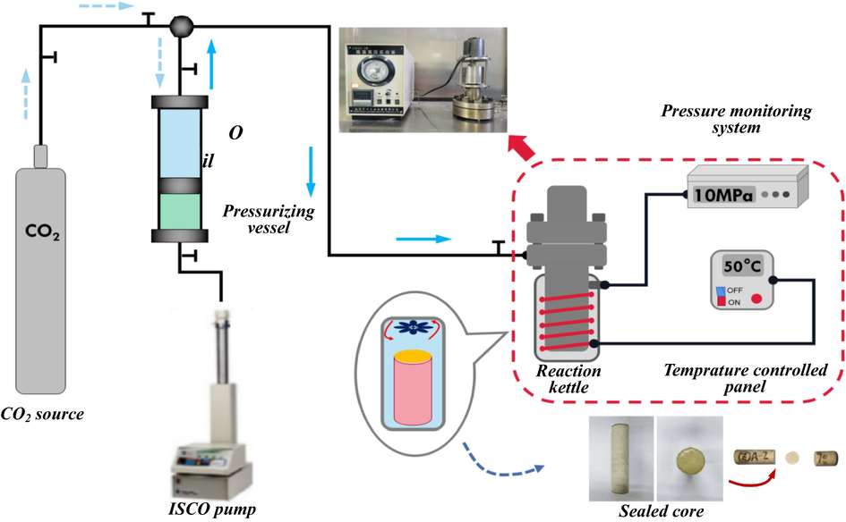
Flow of CO2 diffusion experiment.
The experimental cores were cut into thin slices along the radial direction, and the adhesion state of the polyacrylamide on the pore and rock particle surfaces was observed by an FEI Quanta 250 field emission environmental scanning electron microscope manufactured by Thermo Fisher, USA. The pore surface morphology of the core was also obtained using X-ray CT scanning.
2.3 Mathematical model
Combined with physical experiments, the diffusion model of CO2 in saturated polymer solution cores was developed. The geometry of the diffusion model is shown as the reaction kettle in Fig. 1. The Stokes-Brinkman equation was used to explain the flow velocity and pressure fluctuations of fluids in porous media, taking into account the properties of fluid diffusion variation in permeable columnar cores. It describes the double diffusion phenomenon caused by joint heat-mass transfer. The properties of CO2 compressibility influencing variable density were considered, and Eqs. (2), 3 were solved by the gas equation of state.
Where μ is the dynamic viscosity of the fluid, kg/(m·s); u is the velocity vector, m/s, ρ is the density of the fluid, kg/m, p is the pressure, Pa;
ɛ is the porosity, k is the permeability of the porous medium, m2, and the mass source, Qm, accounts for mass deposit and mass creation within the domains. The mass exchange is assumed to occur at zero velocity.
is the viscous part of the stress. The Maxwell-Stefan diffusion model was used to describe the diffusion process of CO2 molecules in porous media. The mass conservation equation for substance i was calculated using the Eq. (4).
is the mass fraction of substance i, Ri is the reaction rate expression, mol/(m3·s).
The relative mass flux within a porous medium was calculated based on the Eq. (5).
is the multicomponent Fick diffusion coefficient, m2/s; (SI unit: 1/m) is the driving force of diffusion, 1/m; T is the temperature, K; is the thermal diffusion coefficient, kg/(m·s); is the diffusion correction factor for porous media, which is related to porosity and fluid tortuosity factor( ).
The diffusion driving force is defined as Eq. (6). The diffusion driving force for each substance depends on the composition, temperature and pressure of the mixture.
is the molar mass of the i; Mn is average molecular mass.
3 Results and discussion
3.1 Dynamic analysis of each diffusion step
The diffusion pressure was adjusted to 5 MPa, and the experimental temperature was 323 K in accordance with the experimental protocol in section 2.2. The dry powders of 12 million and 19 million molecular weight polyacrylamide were formulated into solutions with 800 ppm, 2000 ppm, and 5000 ppm concentrations. The results of the pressure variation of the diffusion experiment under different conditions are shown in Fig. 2.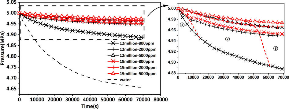
Circumferential pressure variation curves of CO2 in saturated polyacrylamide solution cores.
The diffusion pressure of CO2 in polyacrylamide solution was divided into three stages depending on the variation, which were the rapidly decreasing pressure stage (RDPS), the gradually decreasing pressure stage (GDPS), and the pressure stabilization stage (PSS). CO2 initially contacted the exterior of the core and entered the pores of the core in unsaturated and partially saturated polymers, causing a quick reduction in pressure. After the gas was completely filled into the pores, the pressure reduction became slower, and the CO2 molecules partially dissolved in the solution while squeezing the polyacrylamide solution, making them closer to each other, leading to a reduction in the ability of CO2 to pass through the pores. Subsequently, the diffusion pressure was nearly smooth and the diffusion capacity was the lowest. Fig. 3 depicts the theoretical process. The amount of CO2 diffusing into the core at each stage was quantified by the method of K-means clustering analysis based on three stages divided by pressure changes. Fig. 4 illustrates the molar mass of CO2 diffusion at different stages. A higher percentage of CO2 entered the core in the RDPS. The amount of CO2 diffusion was less in the PSS.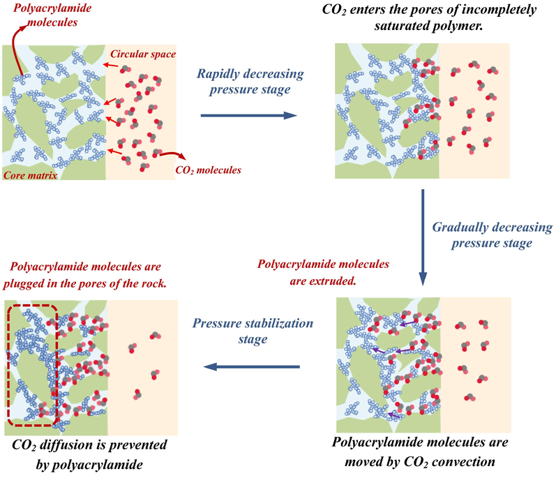
Diffusion process of CO2 in saturated polyacrylamide solution cores.
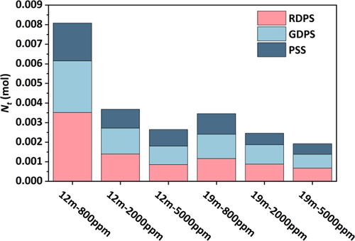
Molar mass of CO2 diffusing into the saturated core at each stages.
3.2 Adhesion pattern of polyacrylamide on core particles
Cores saturated with the 12 million molecular weight, 2000 ppm concentration of polyacrylamide solution were prepared. After CO2 diffusion experiments, the wire saw without water lubrication was used in the middle of the core to cut a thin section of 3 mm thickness. SEM was used to analyze the polyacrylamide solution on the surface of the particles after lyophilization.
Fig. 5 depicts the microscopic characteristics of a three-part region along the radial direction of the core slice. Fig. 6-(a) and (b) represent the states of polyacrylamide adhesion on the rock particles near the core axis. The polyacrylamide clusters were irregularly covered on the surface, showing a lamellar pattern. The irregular polyacrylamide adhesion area was reduced on the outer side of the core (Fig. 6-(c), (d)). The amount of polyacrylamide adhesion was indicated based on the average content of carbon elements in the SEM images. The content of carbon elements radially outward along the center of the slice ranged from 57.41% to 24.05%. It indicated a corresponding decrease in polyacrylamide solution mass content from region A to region C.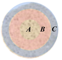
The observation areas on the slice, where A is the area near the axis, B is the area in the middle of the core radius, and C is the outer area of the core.
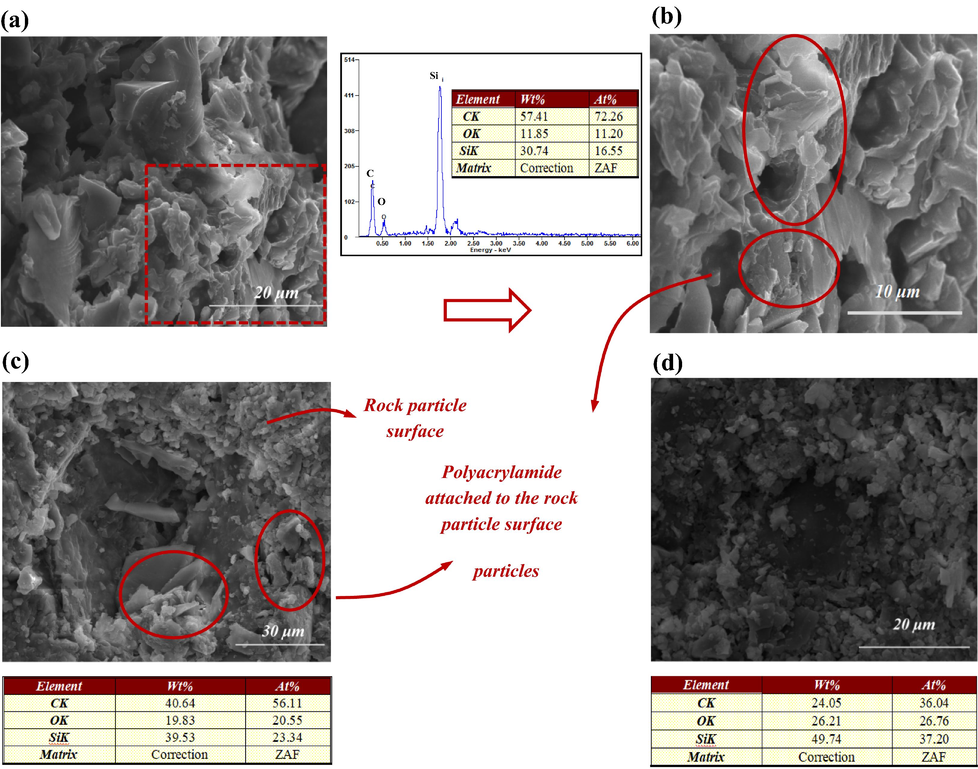
Microscopic features of different areas on the core slice. (a) is a SEM image of core area A, (b) is an enlargement of (a), (c) and (d) correspond to area B and C, respectively. Note: The data in the table are the average values of the elements at different positions in the SEM images.
3.3 Numerical calculation of CO2 diffusion process
The initial conditions of the experimental process were described mathematically in Section 2.3. The initial conditions inside the core and the reactor annulus (Fig. 7) are represented in Table 2.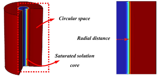
Geometry of the calculation model.
Mathematical equations
Parameters
Position
inside the core
reactor annulus
Stokes–Brinkman equation
Initial pressure
0
Setting pressure
Dynamic viscosity
Polyacrylamide
CO2
Maxwell–Stefan equation
Molar mass
Polyacrylamide
CO2
Mass fraction
Polyacrylamide concentration setting value; CO2 mass fraction is 0
Polyacrylamide concentration is 0; CO2 mass fraction is 1
Diffusion coefficient
Trial value
0
The mass of CO2 entering the core increased as the diffusion coefficient increased (Fig. 8). The reaction kettle was a closed experimental environment, and the diffusion coefficient varied dynamically with the pressure. However, considering the small variation in differential pressure, the diffusion coefficient could be approximated as a constant value in the calculation process. In the process of changing the diffusion coefficient, the difference in diffusion volume was mainly reflected in the RDPS. For the 1900 million molecular weight, 2000 ppm polyacrylamide solution, the CO2 diffusion coefficient was in the range of 5 × 10-13 to 1 × 10-12 m2/s at 5 MPa. Fig. 9 represents the calculation of the CO2 diffusion coefficient under the condition of increasing the pressure in the reactor. As the pressure increased, the diffusion coefficient increased. In the pressure range studied at present, the diffusion coefficients were in the order of 10-12 m2/s.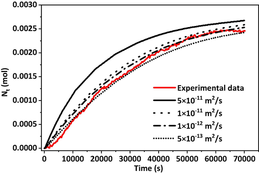
Fitting of CO2 diffusion coefficient in 19 million–2000 ppm polyacrylamide solution (323 K).
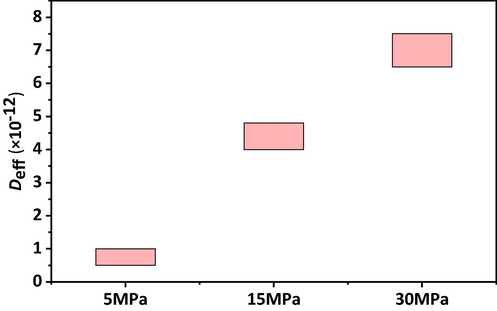
CO2 diffusion coefficients at different pressures in 19 million–2000 ppm polyacrylamide solution (323 K).
The mass fraction of CO2 intrusion at different locations was calculated. Fig. 10 illustrates the diffusion of CO2 after changing the initial pressure. As the initial pressure increased, the CO2 intrusion distance increased, although it was mostly distributed in the outside region of the core. The CO2 mass fraction near the center of the core converged at 0.19 million–2000 ppm polyacrylamide solution, which had the effect of impeding CO2 diffusion in the current permeability range of the core.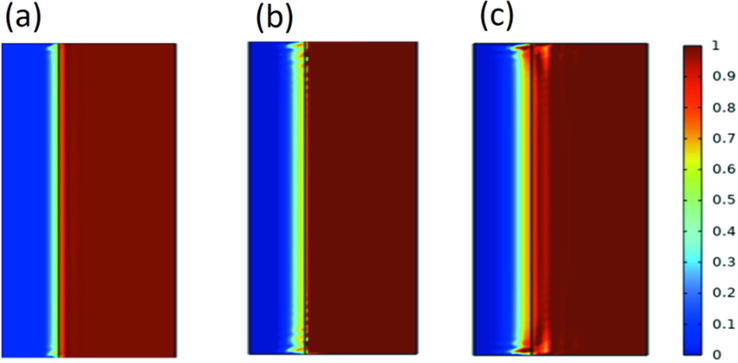
CO2 mass fraction distribution (70000 s), where the initial pressures of (a), (b), and (c) are 5 MPa, 15 MPa, and 30 MPa, respectively (323 K).
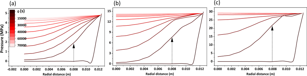
The intrusion distance increased from 3.5 to 7.5 mm as the pressure increased from 5 to 30 MPa, and the CO2 mass fraction curve gradually developed an “S” pattern, with a smooth section at the outer edge of the core, as shown in Fig. 11. The CO2 on the exterior of the core was close to saturation, and the saturated CO2 mass fraction was maintained at 60% to 72%. A cliff-like decrease in CO2 mass fraction occurred during the process toward the inner part of the core. At this stage, the polyacrylamide solution had achieved its purpose of inhibiting CO2 diffusion, and the action range was 4–5 mm, which was the effective action area. The mass fraction of CO2 at different locations approached smoothness as time passed, and the stability of CO2 distribution was reached at 30,000 s.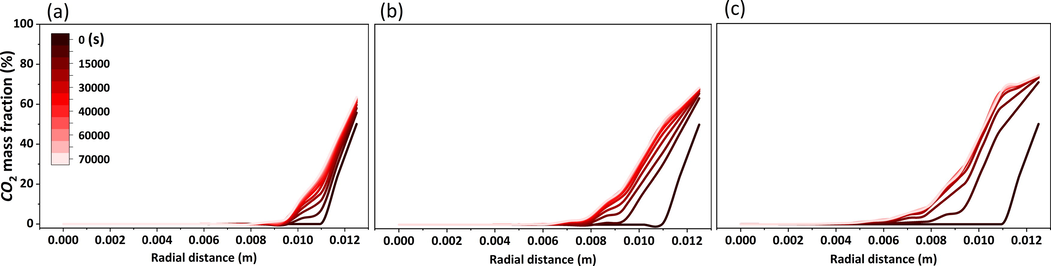
CO2 mass fraction at radial distance variation with time (323 K). The initial pressures for (a), (b), and (c) are 5 MPa, 15 MPa, and 30 MPa, respectively.
In Fig. 12, the pressure inside the core gradually increased, and the pressure values in all parts of the core in the axial direction were consistent, while there was a slight decrease in the pressure inside the annular space. It could be seen that the higher the pressure inside the reactor, the easier the pressure variation inside the core tends to be smooth, combined with the pressure variation inside the core represented in Fig. 13. The polyacrylamide solution was easily compressed, which achieved the purpose of maintaining the pressure balance inside the core. Under the current pressure conditions, the pressure inside the core reaches complete stability in 30,000–60,000 s.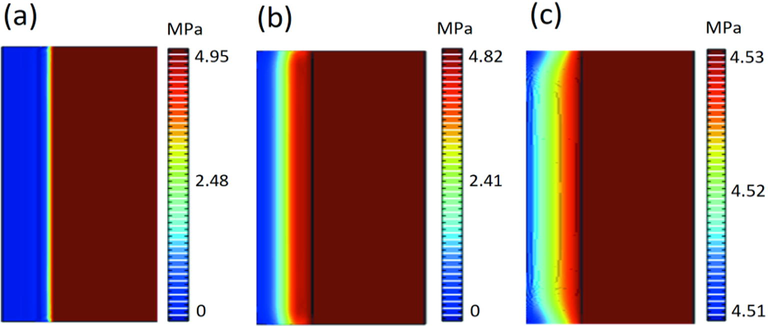
Pressure variation distribution in the core, (a), (b), (c) are the pressure variation in the core at 0 s, 10000 s, and 70000 s respectively.
Pressure in the core along the radial distance with time (323 K). The initial pressures for (a), (b), and (c) are 5 MPa, 15 MPa, and 30 MPa, respectively.
3.4 Analysis of the factors influencing CO2 diffusion
3.4.1 Effect of molecular weight and concentration of polyacrylamide on CO2 diffusion
The increase in molecular weight and concentration of polyacrylamide decreased the diffusion of CO2, as shown in Fig. 2. Molecular weight and concentration exhibited the same function of impeding CO2 diffusion. (12 million molecular weight–2000 ppm and 19 million molecular weight–800 ppm polyacrylamide solutions had the same inhibiting ability for CO2 diffusion).
The increase in the concentration of polyacrylamide solution drastically reduced the diffusion capacity of CO2. With the increase in concentration, the time of RDPS was shortened and the time of PSS was increased. When the concentration was fixed, increasing the molecular weight of polyacrylamide showed the same pattern of change.
3.4.2 Effect of temperature and pressure on CO2 diffusion
Considering the cost of use and the effectiveness of inhibiting CO2 diffusion, a polyacrylamide solution with the 19 million molecular weight and 2000 ppm concentration was selected for temperature and pressure tests. The effect of the change in environmental conditions on the diffusion of CO2 in the polyacrylamide solution was determined.
Fig. 14 demonstrates the effect of temperature and pressure on the diffusion ability of CO2 in the same saturated polyacrylamide solution core. An increase in temperature decreased the effect of polyacrylamide molecules on CO2 sequestration (Fig. 14-(a)), and temperature uniformly affected the three diffusion stages to a lesser extent. However, the CO2 diffusion was more pronounced when compared to the initial pressure increase in the reactor (Fig. 14-(b)). During the RDPS, as the pressure increased, more CO2 entered the core and reached the PSS earlier. The increase in initial pressure caused an increase in the molecular weight of CO2 in the reactor compared to the increase in ambient temperature. The higher concentration difference between the inside and outside of the core elevated the rate of free molecular movement and accelerated the diffusion of CO2 into the polyacrylamide solution.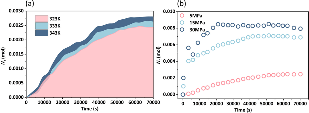
CO2 diffusion in polyacrylamide solution under different conditions. (a) CO2 diffusion in 19 million-2000 ppm polyacrylamide solution at different temperatures (5 MPa), (b) CO2 diffusion in 19 million-2000 ppm polyacrylamide solution at different pressures (323 K).
3.4.3 Effect of rock pore throat size on CO2 diffusion
The Fig. 15-a shows the core pore structure identified using X-ray computed tomography, and the geometric model was constructed based on the identification results. The model size was 4.2 mm × 4.2 mm × 0.3 mm, and the pore size ranges from 27 to 307 μm. At constant pressure conditions, CO2 was sequestered in a rectangular area, and the pores were saturated with a 19 million molecular weight, 2000 ppm concentration polyacrylamide solution.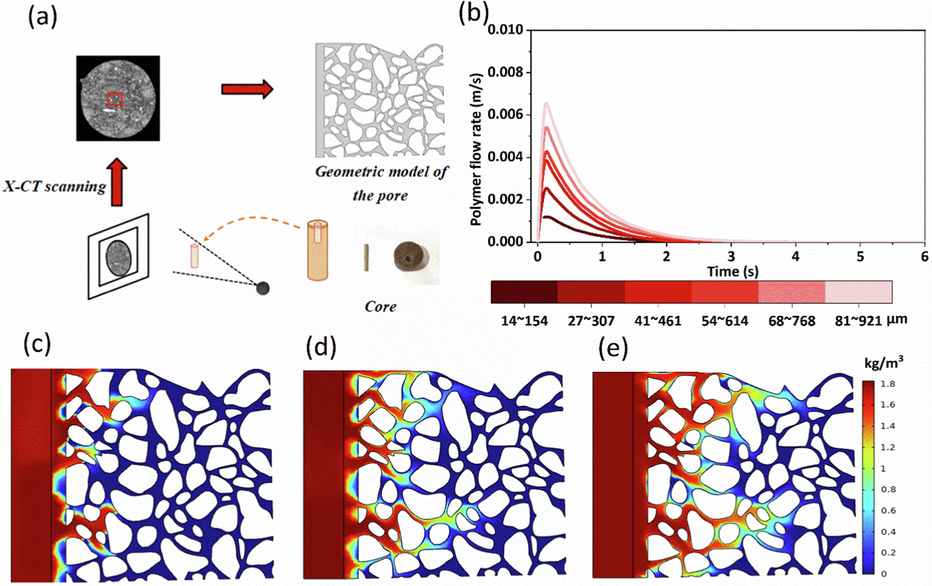
CO2 diffusion characteristics in saturated solution with different pore sizes. (a) is the pore geometry model; (b) is the polymer flow rate for different pore sizes; (c), (d), (e) are the CO2 mass concentration distributions corresponding to 14–154 μm, 41–461 μm, and 91–921 μm pore sizes, respectively.
The size of the geometric model was adjusted separately to calculate the flow velocity of the solution and the mass concentration of CO2 intrusion into the pores at 14–154 μm, 27–307 μm, 41–461 μm, 54–614 μm, 68–768 μm, and 91–921 μm pore sizes, respectively. CO2 flows through the pores of saturated polyacrylamide solution along continuous and larger pore throat size channels, forming dominant channels (Fig. 15-c, d, and e). The large size pores were first plugged in the process of injecting polyacrylamide solution into the formation, so the purpose of plugging CO2 was achieved. However, the polyacrylamide solution between the prominent channels had little effect on inhibiting CO2 diffusion. Fig. 15-b represents the flow velocity of the solution for different pore sizes. Its values gradually increased with time when CO2 was first released due to the weak compressibility of the polyacrylamide solution.
The outflow velocity reached a maximum after the polyacrylamide molecules squeezed each other. As the solution started to plug CO2, the flow velocity decreased until it was 0. The flow velocity increased with the increase in pore size, and the peak value was reached after changing different pore sizes. However, the flow rate was faster, and its sequestration rate was accelerated.
4 Conclusions
In summary, the polyacrylamide was effective in inhibiting CO2 under reservoir conditions. The diffusion of CO2 in the core of a saturated polyacrylamide solution was divided into three stages depending on the degree of pressure change. The pressure data, scanning electron microscopy, and energy spectra confirmed that after CO2 diffusion, it moved the polyacrylamide solution until plugging was achieved. The effects of molecular weight, concentration, pressure, and temperature on the dynamic diffusion of CO2 in the core of saturated polyacrylamide molecules were clarified using diffusion experiments. Polyacrylamide solutions with molecular weights of 12 and 19 million were studied to hinder the diffusion state of CO2 and were formulated to 800 ppm, 2000 ppm, and 5000 ppm concentrations, respectively. The increase in molecular weight and concentration exhibited the same function of impeding CO2 diffusion. In addition, the pressure range of this experiment was 5–30 MPa and the temperature was 323–343 K. The increase in temperature decreased the effect of polyacrylamide molecules on CO2 sequestration, uniformly affecting the three diffusion stages. However, the initial pressure in the reactor increased, and the CO2 diffusion was more rapid. The increase in pore size accelerated the flow rate of the polymer. The range of sizes studied can also have a sequestering effect.
The results calculated using a combination of the mathematical models correspond well to the experimental results. The CO2 diffusion coefficient in the polyacrylamide was calculated to be on the order of 10-12 m2/s at a core permeability of 60 × 10-3 μm2. The mass fraction and pressure of CO2 in the core were given. The external side of the core was saturated with a CO2 mass fraction in the range of 60% to 72%. The CO2 mass fraction in the interior of the core was substantially reduced. The polyacrylamide achieved the purpose of plugging CO2 diffusion. The results presented in this paper provide a new computational method to evaluate the CO2 sequestration effect of polymers.
Acknowledgements
This work was supported by the National Natural Science Foundation of China (No. 51574089).
Declaration of Competing Interest
The authors declare that they have no known competing financial interests or personal relationships that could have appeared to influence the work reported in this paper.
References
- A review of CO2 storage in geological formations emphasizing modeling, monitoring and capacity estimation approaches. Pet. Sci.. 2019;16:1028-1063.
- [CrossRef] [Google Scholar]
- Bio-energy with carbon capture and storage (BECCS): Opportunities for performance improvement. Fuel. 2018;213:164-175.
- [CrossRef] [Google Scholar]
- A dynamic model of CO2 diffusion coefficient in shale based on the whole process fitting. Chem. Eng. J.. 2022;428:131151
- [CrossRef] [Google Scholar]
- Energy expenditure, economic growth, and the minimum EROI of society. Energy Policy. 2016;95:172-186.
- [CrossRef] [Google Scholar]
- Development and testing of a foam-gel technology to improve conformance of the Rangely CO2 flood. SPE Reservoir Eval. Eng.. 1999;2(01):4-13.
- [CrossRef] [Google Scholar]
- Research on a novel composite gel system for CO2 breakthrough. Pet. Sci.. 2010;7:245-250.
- [CrossRef] [Google Scholar]
- Cross-linked polyacrylamide gel as loss circulation materials for combating lost circulation in high temperature well drilling operation. J. Pet. Sci. Eng.. 2019;181:106250
- [CrossRef] [Google Scholar]
- The role of carbon capture and storage in the energy transition. Energy Fuels. 2021;35(9):7364-7386.
- [CrossRef] [Google Scholar]
- CO2-triggered gelation for mobility control and channeling blocking during CO2 flooding processes. Pet. Sci.. 2016;13:247-258.
- [CrossRef] [Google Scholar]
- Field validation of supercritical CO2 reactivity with basalts. Environ. Sci. Technol. Lett.. 2017;4(1):6-10.
- [CrossRef] [Google Scholar]
- A simplified model correlating the excess proprieties for Bi-X binary systems (X= Cu, Sb) serving the concept of reduced Redlich-Kister function at different temperatures. Surf. Interfaces. 2020;21:100643
- [CrossRef] [Google Scholar]
- Investigating the application of enzyme carbonic anhydrase for CO2 sequestration purposes. Ind. Eng. Chem. Res.. 2007;46(3):921-926.
- [CrossRef] [Google Scholar]
- Simplification of detailed rate-based model of post-combustion CO2 capture for full chain CCS integration studies. Fuel. 2015;142:87-93.
- [CrossRef] [Google Scholar]
- CO2 capture and separation technologies for end-of-pipe applications–A review. Energy. 2010;35(6):2610-2628.
- [CrossRef] [Google Scholar]
- Parameters optimization for direct flue gas CO2 capture and sequestration by aqueous mineral carbonation using activated serpentinite based mining residue. Appl. Geochem.. 2014;50:66-73.
- [CrossRef] [Google Scholar]
- Co-firing coal with biomass in oxygen-and carbon dioxide-enriched atmospheres for CCS applications. Fuel. 2014;137:185-192.
- [CrossRef] [Google Scholar]
- Enzyme mediated transformation of CO2 into calcium carbonate using purified microbial carbonic anhydrase. Environ. Res.. 2022;212:113538
- [CrossRef] [Google Scholar]
- Dehydration of polyacrylamide-based super-absorbent polymer swollen in different concentrations of brine under CO2 conditions. Fuel. 2017;210:32-40.
- [CrossRef] [Google Scholar]
- Understanding the plugging performance of HPAM-Cr (III) polymer gel for CO2 conformance control. SPE J.. 2021;26(05):3109-3118.
- [CrossRef] [Google Scholar]
- Gas cleaning challenges for coal-fired oxy-fuel technology with carbon capture and storage. Fuel. 2013;108:85-90.
- [CrossRef] [Google Scholar]
- The potential of coupled carbon storage and geothermal extraction in a CO2-enhanced geothermal system: a review. Geotherm. Energy. 2020;8(1):1-28.
- [CrossRef] [Google Scholar]
- High-temperature-resistant, low-concentration water-controlling composite cross-linked polyacrylamide weak gel system prepared from oilfield sewage. ACS omega. 2022;7(15):12570-12579.
- [CrossRef] [Google Scholar]
- Toward the development and deployment of large-scale carbon dioxide capture and conversion processes. Ind. Eng. Chem. Res.. 2016;55(12):3383-3419.
- [CrossRef] [Google Scholar]
- A polyacrylamide hydrogel for application at high temperature and salinity tolerance in temporary well plugging. Iran. Polym. J.. 2018;27:577-587.
- [CrossRef] [Google Scholar]
- Polyacrylamide gel formed by Cr (III) and phenolic resin for water control in high-temperature reservoirs. J. Pet. Sci. Eng.. 2020;194:107423
- [CrossRef] [Google Scholar]
Appendix A
Supplementary material
Supplementary data to this article can be found online at https://doi.org/10.1016/j.arabjc.2023.105106.
Appendix A
Supplementary material
The following are the Supplementary data to this article:Supplementary data 1
Supplementary data 1


