

Translate this page into:
Chemical deposition from a liquid crystal template: A highly active mesoporous nickel phosphate electrocatalyst for hydrogen green production via urea electro-oxidation in an alkaline solution
⁎Corresponding author. mghanem@ksu.edu.sa (Mohamed A. Ghanem)
-
Received: ,
Accepted: ,
This article was originally published by Elsevier and was migrated to Scientific Scholar after the change of Publisher.
Peer review under responsibility of King Saud University.
Abstract
Recently the urea and urinated wastewater electrolysis process has shown promising technology for hydrogen fuel green production in addition to denitrification of wastewater. However, to make the process economically valuable, the electrocatalysts nanoarchitecture, nanometer size, shape, facets, and composition need to be engineered to boost the urea oxidation reaction (UOR). This work demonstrates a simple and novel approach to the synthesis of mesoporous nickel phosphate nanoparticles (meso-NiPO) via chemical deposition from a surfactant liquid crystal template. Typically, the nickel ions dissolved in the aqueous domain of the hexagonal liquid crystalline phase of the Brij®78 template were chemically reacted with the sodium phosphate solution to precipitate the mesoporous nickel phosphate nanoarchitecture after washing up the surfactant. The physicochemical characterizations show the meso-NiPO exhibits an amorphous highly mesoporous structure with a higher specific surface area (43.50 m2/g) compared to the bare nickel phosphate (bare-NiPO, 4.26 m2/g) prepared in the absence of surfactant. The electrochemical performance of meso-NiPO electrocatalyst for the urea oxidation reaction in alkaline solution exhibits superior activity including a lower oxidation onset potential (0.30 V vs. Ag/AgCl), charge transfer resistance (3.35 O) and mass activity of 700.7 mA/cm2 mg at the oxidation potential of 0.6 V vs. Ag/AgCl. Moreover, the meso-NiPO reveals long-term stability, and 97.5% of the steady-state oxidation current was maintained after the 3-hour urea electrolysis test. Using an H-shape urea electrolyzer, the corresponding cathodic hydrogen production rate reached 415 µmol/h and a Faradic efficiency of 96.8 % at an applied bias of 2.0 V. The electroactivity high performance of the mesoporous nickel phosphate is ascribed to the high specific surface area and mesoporous architecture that provide efficient charge transfer, as well as mass transport of the electroactive species. The chemical deposition from a surfactant liquid crystal template has the advantages of a one-pot template, applicable to the synthesis of a wide range of nanomaterials with various compositions and nanoarchitectures at room temperature for application in electrochemical energy production and storage systems.
Keywords
Surfactant
Mesoporous nickel phosphate
Urea oxidation reaction
Liquid crystal template
Hydrogen production

1 Introduction
Recently, the demand for renewable energy supplies has promoted the search for alternative energy sources to fossil fuels (Megía et al., 2021). Research has focused on urea and urinated wastewater electrolysis for hydrogen fuel (H2) green production as well as the remedy of the environmental impact (Zhu et al., 2020; Hu et al., 2020). Several proposed approaches and catalysts have been suggested for urea electrolysis to produce hydrogen and denitrification of wastewater but they suffer from the limited efficiency, high costs and instability of the electrode materials (Deng et al., 2022; Liu et al., 2017a, 2017b; Yan et al., 2014; Li et al., 2022). Urea electro-oxidation reaction (UOR) in an alkaline medium, as a proficient approach, has been proposed to be an economically feasible green method for producing pure H2 at the cathode and nitrogen (N2) and carbon dioxide (CO2) at the anode (Boggs et al., 2009; Zhang et al., 2019). In standard conditions, hydrogen production via urea electrolysis occurs at an overpotential of 0.37 V which is thermodynamically more favorable than the water splitting potential of 1.23 V and produces approximately 70% cheaper hydrogen fuel (Yan et al., 2014; Li et al., 2022; Boggs et al., 2009). However, the UOR kinetics are slow which may restrict the use of urea fuel in large-scale and industrial H2 green production. Consequently, various catalysts of noble and earth-abundant-based electrodes have been employed to overcome the sluggish kinetics and inefficient urea electrooxidation (Deng et al., 2022; Liu et al., 2017a, 2017b; Yan et al., 2014; Li et al., 2022; Boggs et al., 2009; Zhang et al., 2019; Xie et al., 2018; Liu et al., 2017a, 2017b; Xie et al., 2017).
The nickel-containing nanomaterials have been widely investigated as efficient alternatives for the noble-metals electrocatalysts for small molecule oxidation, especially methanol and urea oxidation reactions in alkaline solution (Babar et al., 2021; Wu et al., 2021; Ye et al., 2018; Shen et al., 2020; Sun et al., 2021; Qian et al., 2020; Wu et al., 2020). However, to enhance the catalytic performance of Ni-based catalysts for urea electro-oxidation in an alkaline medium and make the process more economically valuable and effective for hydrogen green production, two main strategies have been employed. Firstly, increasing the specific electroactive surface and enhancing the reaction current density via using nanostructured porous electrodes (Ghanem et al., 2017; Barakat et al., 2016; Ding et al., 2016a, 2016b; Ding et al., 2014). Secondly is to synthesize nickel-based alloys and compounds with multifunctional redox systems such as Ni—Co (Ding et al., 2016a, 2016b; Ding, et al., 2014; Sun, et al., 2020), Ni—Zn (Yan, et al., 2012) or Ni-Carbon sponge (Ye, et al., 2015) which moderate the adsorption energy and reduce the urea oxidation overpotential. Within this context, mesoporous transition metals compounds, such as nickel phosphate, have unique properties that make them suitable for catalyzing the hydrogen production process and energy conversion applications (Hassaninejad-Darzi et al., 2016; Omar et al., 2018; Omar et al., 2016; Pujari et al., 2021; Zhou et al., 2019; Nwodo et al., 2023; Aziam et al., 2020; Saravanakumar et al., 2020). Song et al. prepared various mesoporous nanoarchitectures (nanotubes, nanosheets and nanocrystals) of nickel phosphate (NiPO) using different preparation methods (Song et al., 2017), showing that the porous NiPO with a nanosheet morphology catalyst exhibits the highest mass activity of 600 mA/cm2 mg at 0.5 V vs. Ag/AgCl and superior durability for UOR in 1.0 M KOH. Similarly, Tsai and Wu et al. developed highly porous and crystalline zeolitic nickel phosphate nanorods by a hydrothermal route for urea oxidation in an alkaline solution (Tsai and Wu, 2020). The nickel phosphate nanorods had a better electrocatalytic performance for UOR in alkaline media compared to the corresponding Ni(OH)2 electrode, achieving a lower onset potential of 0.27 V and higher urea-specific activity of 160 mA/cm2. Moreover, Yang et. al (Yang et al., 2019) synthesized NiCoPO electrocatalysts for methanol and UOR in an alkaline solution, reporting that the introduction of Co into the NiPO matrix led to an effective increase in the anodic current and a decrease in the onset potential by 0.135 V. Interestingly, Sha et. al (Sha et al., 2019) grew NiCo2O4 nanowires on a nickel foam substrate by a hydrothermal method to produce an electrocatalyst with an excellent urea oxidation current in 5.0 M KOH due to more active sites in the 3D nanowire morphology. In addition, Ding et. al (Ding et al., 2016a, 2016b) reported mesoporous Ni-P by a solvothermal approach to obtain Ni-P nano-catalysts with a lower onset potential of 1.37 V vs. RHE and good urea oxidation currents of 70 mA/cm2 which is better than the pure Ni nano-catalysts under similar conditions.
Within this context, our research group has reported the precipitation of a mesoporous cobalt phosphate (meso-CoPi) electrocatalyst from a liquid crystal template in ambient conditions (Al-Sharif et al., 2020) for enhancing the methanol oxidation in alkaline solution. The meso-CoPi structure comprises cobalt-oxo/hydroxo-phosphate and metallic cobalt layers that enhanced methanol oxidation at an overpotential of < 1.2 V vs. RHE with more than a 20-fold current increase at 1.4 V RHE compared to the bulk-CoPi counterpart prepared in absence of surfactant. The methanol oxidation activity boosting at meso-CoPi was credited to the specific surface area enhancement created by chemical precipitation through the liquid crystal template.
Herein, we report a novel and simple synthesis approach to prepare mesoporous nanoparticles of nickel phosphate (meso-NiPO) having a larger surface area (43.50 m2/g) via direct chemical precipitation within the self-assembly Birj@78 surfactant template at ambient conditions. The nickel ions dissolved in the aqueous domain of the hexagonal liquid crystalline phase of the Brij@78 template were directly reacted with sodium phosphate solution to precipitate the mesoporous nickel phosphate compound. Various techniques including XRD, BET, EDX, scanning and transmission electron microscope were employed to characterize the deposited meso-NiPO materials. The electrocatalytic performance of mesoporous NiP toward the oxidation of urea is evaluated through various electrochemical techniques, including cyclic voltammetry (CV), chronoamperometry (CA), and electrochemical impedance spectroscopy (EIS), measurements. The influence of factors such as catalyst loading, urea concentration, and KOH concentration on the electrocatalytic activity and stability are studied to optimize the catalyst's performance. The electrochemical behaviour and the electrocatalytic performance and stability of the mesoporous nickel phosphate nanoparticles in UOR in alkaline conditions were investigated by cyclic voltammetry, chronoamperometry and electrochemical impedance spectroscopy. The meso-NiPO catalyst shows significant urea oxidation enhancement with lower charge transfer resistance and higher mass activity compared to the bare nickel phosphate (bare-NiPO) prepared in the absence of surfactant. The synthesis approach opens a new opportunity to prepare new mesoporous catalyst nanoarchitectures with improved activity for applications in urea fuel cells and hydrogen green production. However, there are challenges such as optimizing the synthesis conditions and catalytic properties of mesoporous compounds and improving their stability and durability under various operating conditions, need to be achieved. Additionally, scaling up the production of mesoporous catalysts to meet the growing demand for hydrogen green production technology will be crucial.
2 Materials and methods
2.1 Chemicals and materials
Nickel nitrate (Ni(NO3)2·6H2O, 98.0%) was obtained from LOBA Chemie and disodium hydrogen phosphate (Na2HPO4·2H2O, 98.0%) was acquired from Molekula. The nonionic surfactant polyethylene glycol octadecyl ether (Birj@78, C18H37(OCH2CH2)20OH, 97.0%), and potassium hydroxide (KOH, 85.0%) were purchased from Sigma-Aldrich. Urea pellets were acquired from AVONCHEM Corp and all chemicals were used without further purification. The hydrophilic carbon paper substrate (HCP030) was used as a working electrode and was purchased from VECK Store (China) and carbon black Vulcan (XC-72R, Fuel store). Nafion™ perfluorinated resin 5 wt% solution of 45% water mixed in aliphatic alcohols was obtained from Merck. Deionized water (resistivity of 18.2 MΩ cm) was obtained from a PURELAB® Flex water distillation machine to prepare all solutions.
2.2 Nickel phosphate (Ni3(PO4)2 nanoparticle synthesis
The nanoparticles of mesoporous nickel phosphate (meso-NiPO) catalyst were synthesized as shown in Scheme 1 via direct chemical precipitation through a self-assembled Brij®78 surfactant template mixed with nickel nitrate solution and followed by spraying of disodium hydrogen phosphate (1.0 M) solution. First, an excess of nickel nitrate solution (10.0 mL, 0.5 M) was mixed with the melted Brij®78 surfactant template (2.0 g) in an ultrasonic bath for 15 min, then the homogenous mixture was cast in a petri dish and was air-dried at room temperature (25 °C) to allow the gelation via water evaporation. After several water evaporation runs monitored by water weight loss using an analytical balance, the desired surfactant/water ratio of about 40 ± 1.0% which corresponds to the hexagonal phase of the liquid crystal template was reached. Then, an excess of disodium hydrogen phosphate solution (5.0 mL, 1.0 M), was sprayed over the template mixture in the petri dish to begin the chemical deposition of nickel phosphate and the mixture was left overnight to complete the precipitation process. The precipitate mixture was collected in a beaker and washed several times (3–4) with plenty of deionised water/acetone mixture (ratio 1:1) to remove the surfactant. the complete removal of the surfactant. Moreover, the complete removal of the surfactant was confirmed by testing the catalyst in 2.0 M KOH by cyclic voltammetry and ensuring the maximum current was obtained for each preparation batch. Finally, the deposited product was obtained via centrifugation and dried in an oven overnight at 60 °C. No carbon contamination was detected by EDX analysis which indicates the successful removal of surfactant. For comparison, the bare catalyst (as a control material) was also prepared under the same condition but in the absence of Brij®78 surfactant and labelled as bare-NiPO.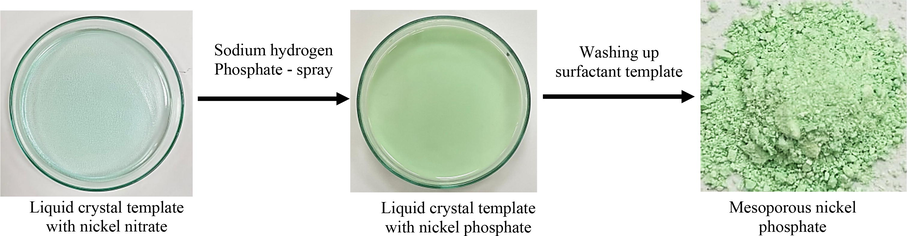
Chemical precipitation of mesoporous nickel phosphate from surfactant liquid crystal template.
2.3 Nickel phosphate (Ni3(PO4)2 catalyst characterisation
The crystal structures of the meso-NiPO catalyst were characterized by X-ray diffraction (XRD, Rigaku Miniflex 600) with graphite monochromatized Cu(Kα) radiation tube operated at 40 KV and current of 15 mA in 2θ range of 5–90° at scan of 2°/min. The surface functionality of the meso-NiPO powder was identified using a Bruker (TENSOR 27) Fourier-transform infrared spectrometer (FTIR). The catalyst-specific surface area was measured using the V-Sorb 2800 Porosimetry analyzer, while the pore size and volume were estimated via the Brunauer Emmer Teller (BET) approach. The scanning electron microscope (SEM, JSM-7600F, Japan) equipped with an energy-dispersive X-ray spectroscopy (EDX) analyzer was employed to examine the surface morphology and elemental composition of the obtained mesoporous nickel phosphate powder, respectively. A transmission electron microscope (TEM, JEM 2100F) was used to study the porous and fine structure of the as-deposited nickel phosphate nanoparticles. Electrochemical measurements of the obtained mesoporous nickel phosphate nanoparticles (meso-NiPO) materials were performed using a biologic electrochemical workstation, including cyclic voltammetry (CV), chronoamperometry (CA), and electrochemical impedance spectroscopy (EIS) in a three-electrode glass cell. The cell consisted of a graphite sheet and Ag/AgCl as counter and reference electrodes, respectively. The working electrode was made of hydrophilic carbon paper (HCP030, 1.0 × 1.0 cm2) loaded with meso-NiPO ink that was prepared by mixing 10 mg of nickel phosphate powder in 1.0 mL of deionised water/isopropanol, 10 μL of Nafion solution (5.0 wt%), and 20 mg of carbon black (Vulcan XC-72R) in an ultrasonic bath for 60 min. The working electrode was prepared by casting the required volume of meso-NiPO ink on the carbon paper electrode and drying it with hot air before executing the electrochemical characterisation experiments.
The volumetric determination of the hydrogen gas production rate and the efficiency was performed using the H-shaped glass electrolyzer as shown in Fig. S4 (Supporting Materials) which consists of anodic and cathodic compartments connected by a central channel. The anode was made of meso-NiPO catalyst (about 0.50 mg/cm2) coated on both sides of carbon paper (2.0 × 3.0 cm2) and nickel foam (2.0 × 3.0 cm2) as a cathode. The electrolyzer was filled with 2.0 M KOH containing 0.33 M urea solution up to the zero-mark level of the cathodic compartment. The urea electrooxidation at the meso-NiPO anode was initiated by applying suitable bias voltage (1.6, 2.0 and 2.5 V) as controlled by the power supply, and then the bubbles of hydrogen gas started to evolve at the nickel foam cathode. As the urea electrooxidation reaction progresses, the volume of the hydrogen gas is monitored at regular intervals until a desired reaction time is achieved.
3 Results and discussion
3.1 Catalyst characterisation
The mesoporous nickel phosphate nanoparticles (Ni3(PO4)2·3H2O) were prepared as shown in Scheme 1 via chemical precipitation from a liquid crystal template using the self-assembled Brij®78 surfactant. In this approach, nickel ions dissolved in the aqueous domain of the surfactant hexagonal template were chemically deposited using excess disodium hydrogen phosphate (Na2HPO4·2H2O) at room temperature. In a typical reaction, the Na2HPO4·2H2O dissociates and releases phosphate ions which react with nickel ions within the aqueous domain of the surfactant liquid crystal template forming hydrated nickel phosphate precipitate (Ni3(PO4)2 (Omar et al., 2018), and the balanced reaction can be represented as shown in Eq. (1).
The crystal structure of an as-synthesized mesoporous nickel phosphate catalyst is shown in Fig. 1a. The broad and low-intensity diffraction peaks indicate the amorphous/semi-crystalline nature of the deposit because the precipitation was performed in ambient conditions. However, the broad diffraction peaks at 2Θ about 7.5, 27.8, 35.2, 52.2 and 62.4° can be assigned to the plane (1 0 0), (1 1 1), (3 1 1), (2 2 2), and (3 1 3 ) respectively, which is consistent with the structure of the hydrate Ni3(PO4)2 (JCPD card no. 038–1473) (Omar et al., 2018; Omar et al., 2016; Pujari et al., 2021). The XRD result of the bare-NiPO deposit is quite similar to the meso-NiPO one indicating both catalysts have an amorphous/semi-crystalline structure. Fig. 1b shows the amorphous meso-NiPO FT-IR spectra characterization along with the bare-NiPO catalyst. The FT-IR spectra show the presence of a strong absorption asymmetric vibration mode at 1070 cm−1 which is characteristic of the vibrational bond of the PO43− group for both meso- and bare-NiPO catalysts. In addition, the peaks at 584 and 907 cm−1 belong to the vibration mode of the phosphate group (PO43−) and the stretching of the P—O—P linkages, respectively, confirming the presence of the phosphate group (Klähn et al., 2004). The two characteristic bands around 3423 and 1641 cm−1 correspond to hydroxyl ion (O—H) stretching and a water molecule (H—O—H) bending modes (Hassaninejad-Darzi et al., 2016). Notably, the band intensities of mesoporous nickel phosphate nanoparticles increased compared to the bare-NiPO catalyst, indicating that meso-NiPO nanoparticles have more phosphate groups and chemisorbed water, presumably due to the presence of mesoporous, structural water and a larger surface area. Fig. 1c shows the N2 adsorption–desorption isotherms of meso-NiPO and bare-NiPO catalysts, which are classified as type IV with a hysteresis loop (Sing et al., 1985) and appeared at a higher relative pressure (p/po) between 0.85 and 0.95, indicating the mesoporous nature of the as-prepared materials. The BET surface area of as-deposited meso-NiPO and bare-NiPO catalysts were 43.50 and 4.26 m2/g, respectively, confirming that the meso-NiPO has a ten times higher mesoporous specific surface area than the bare-NiPO. The inset in Fig. 1c shows the corresponding pore size distribution of the meso-NiPO and bare-NiPO catalysts with polynomial pore diameters in the range of 3.0, 4.0 and 6.5 nm. This is consistent with the TEM characterisation images in Fig. 2c below that revealed the formation of disordered and irregular pores using the soft surfactant template.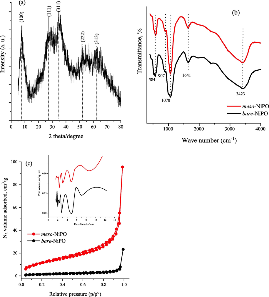
(a) XRD pattern of as-deposited meso-NiPO nanoparticles, (b) the FT-IR spectrum of amorphous meso-NiPO and bare-NiPO catalysts, (c) N2 gas adsorption–desorption isotherms of amorphous meso-NiPO and bare-NiPO catalysts, and the inset shows the corresponding BJH desorption pore size distribution curves.
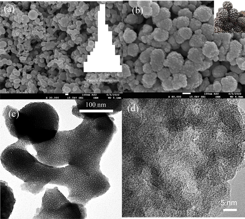
(a-b) SEM images at different magnifications, the insets show the nanoparticles size histogram and berry fruit image and (c-d) TEM photographs of meso-NiPO catalyst at different magnifications, the yellow circles highlighted the mesopores.
The surface morphology and bulk composition of the hydrated meso-NiPO (Ni3(PO4)2) nanoparticles are shown in Fig. 2 a and b, indicating that the meso-NiPO deposit has “berry fruit” like morphology (inset Fig. 2b) with very small nanoparticles (20–25 nm average size) assembled into semispherical larger particles with an average size of 175 nm as shown in the inset histogram in Fig. 2a. Fig. 2c shows a lower magnification TEM image of meso-NiPO nanoparticles that confirms the formation of the highly mesoporous network left after the removal of the Brij®78 surfactant template. The high-resolution TEM microphotograph shown in Fig. 2d indicates that the mesopore is arranged in a disordered structure with various-sized pores (≤5 nm) and little lattice fringes can be observed confirming its amorphous/semicrystalline structure, which is consistent with the N2 adsorption–desorption isotherms and XRD analysis shown above. This could be due to the surfactant liquid crystal template being a soft scaffold that easily changes during the chemical precipitation of nickel phosphate within the aqueous domain of the template and the hydrophobic Brij®78 surfactant renders the formation of crystalline structure.
Moreover, Fig. 3 shows the EDX elemental mapping analysis of meso-NiPO nanoparticles confirming the presence and uniform distribution of Ni, P and O elements with the elemental composition of 48.10, 12.40, and 39.50 wt% respectively, consistent with the chemical stichometric of Ni3(PO4)2 and considering an excess of oxygen due to the formation of the hydrated form of the Ni3(PO4)2.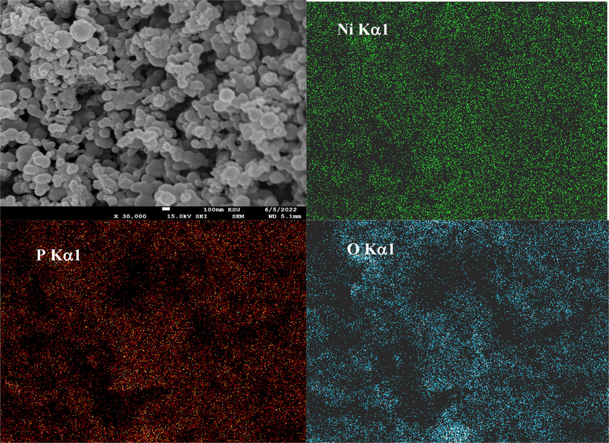
EDX elemental mapping of as-prepared mesoporous nickel phosphate.
3.2 Electrochemical characterization of the meso-NiPO nanoparticles
Fig. 4a shows the cyclic voltammograms responses of the meso-NiPO and bare-NiPO catalysts loaded on the CP electrode (200 µg/cm2) at 50 mV/s in 2.0 M KOH within the potential range from −0.20 to 0.60 V vs. Ag/AgCl. The meso-NiPO and bare-NiPO electrodes display a pair of well-defined anodic and cathodic peaks located at 0.36 and 0.25 V vs. Ag/AgCl respectively corresponding to the redox reaction of Ni(II)/Ni(III) phosphate with hydroxyl ions (OH−) during the potential cycling forming Ni3(OH)3(PO4)2 according to Eq. (2) (Al-Omair et al., 2017; Touny and Saleh, 2018). Interestingly, the redox peak current density at the meso-NiPO is more than four times higher than that recorded at the bare-NiPO electrode, indicating that the meso-NiPO catalyst has more surface area and electrochemical active sites due to the presence of mesoporous network structure. In addition, the more negative shift in the onset potential observed at the meso-NiPO catalyst suggests a more easy reaction with hydroxide ions according to Eq. (2).
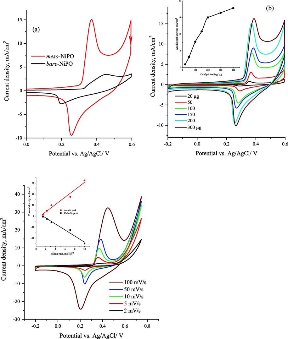
(a) cyclic voltammograms responses of both meso-NiPO nanoparticles and bare-NiPO catalysts loaded on CP electrode (200 µg/cm2) at 50 mV/s in 2.0 M KOH solution, (b) cyclic voltammograms of different loadings of meso-NiPO in 2.0 M KOH at 50 mVs−1, the inset shows the relationship between anodic peak currents and catalyst loading, and (c) cyclic voltammograms of 200 µg/cm2 of meso-NiPO nanoparticles at different scan rates in 2.0 M KOH, and the inset shows the relationship between peak currents and the square root of the scan rate.
Fig. 4b shows the influence of different meso-NiPO loadings (20, 50, 100, 200, 300, and 400 µg) on the Ni(II)/Ni(III) redox peak currents in 2.0 M KOH at 50 mVs−1. As shown in the inset in Fig. 4b, the Ni(II)/Ni(III) redox peak current density gradually increased as the meso-NiPO loading increased from 20 to 200 µg, then became saturated at higher loading of 300 and 400 µg. This behaviour can be attributed to an increase in the electrochemically active surface area and catalytic active sites as the catalyst loading increased. However at higher catalyst loading (>200 µg) the current density saturated or declined due to layer thickness increases at higher loading that limits hydroxide ion diffusion and accessibility to the catalyst active sites. Furthermore, the effect of various scan rates on the redox process of meso-NiPO nanoparticles (loading 200 µg) is shown in Fig. 4c. The CVs response shows the redox peak currents increase with the potential scan rates from 2.0 to 100 mV/s, with a linear relationship between the redox peak currents and the square root of the scan rates (inset in Fig. 4c), confirming the reaction of hydroxide ions with meso-NiPO nanoparticles (Eq. (3)) proceeding in a diffusion-controlled process.
Fig. 5a shows the cyclic voltammograms of the 200 µg/cm2 of meso-NiPO nanoparticles electrode in the absence and presence of 0.33 M urea and 2.0 M KOH solution compared to the bare-NiPO electrode at 50 mV/s scan rate. The CVs response of the meso-NiPO catalyst in 2.0 M KOH displays anodic and cathodic peak currents at 0.36 and 0.25 V vs. Ag/AgCl respectively corresponding to the redox transformations of Ni(II)/Ni(III) species (Hu et al., 2020; Al-Sharif et al., 2020; Klähn et al., 2004). The CVs responses of the meso-NiPO electrode in 0.33 M urea solution exhibit a dramatic increase in the anodic urea oxidation current at the same onset potential of 0.30 V where the Ni(II)/Ni(III) species are formed, indicating that meso-NiPO nanoparticles catalyse the UOR (Wu et al., 2020; Song et al., 2017; Tsai et al., 2020; Yang et al., 2019; Sha et al., 2019; Ding et al., 2016a, 2016b). The meso-NiPO electrode reveals significant activity enhancement toward UOR compared with the bare-NiPO electrode, achieving specific activity of 141.4 mA/cm2 at a potential of 0.60 V vs. Ag/AgCl (equivalent to the mass activity of 700.7 mA/cm2 mg) which was about 4.5-fold higher than the bare-NiPO electrode (31.0 mA/cm2). The urea oxidation current enhancement at the meso-NiPO catalyst is attributed to the high specific surface area and mesoporous architecture that provide more active sites, efficient charge transfer, as well as higher mass transport of the electroactive species. Moreover, the meso-NiPO catalyst displays a UOR onset potential of 0.30 V vs. Ag/AgCl, which is lower than the onset potential of the bare-NiPO catalyst (0.34 V), indicating that the UOR thermodynamically is more favourable at the mesoporous structure of Ni3(PO4)2 catalyst. As shown in the inset in Fig. 5a, the meso-NiPO electrode displays a Tafel slope of 20.3 m/dec which is lower than that of the bare-NiPO (30.2 mV/dec), indicating faster kinetics and charge transfer of catalytic urea oxidation at meso-NiPO compared to the bare-NiPO catalyst. It is worth noting that the onset potential of oxygen evolution reaction in the absence of urea occurs at above 0.55 V vs. Ag/AgCl. In contrast, the urea onset oxidation potential occurs at around 0.30 V vs. Ag/AgCl which is about 0.25 V less than the oxygen evolution reaction which signifies the benefit of using urea instead of water for cheaper hydrogen green production.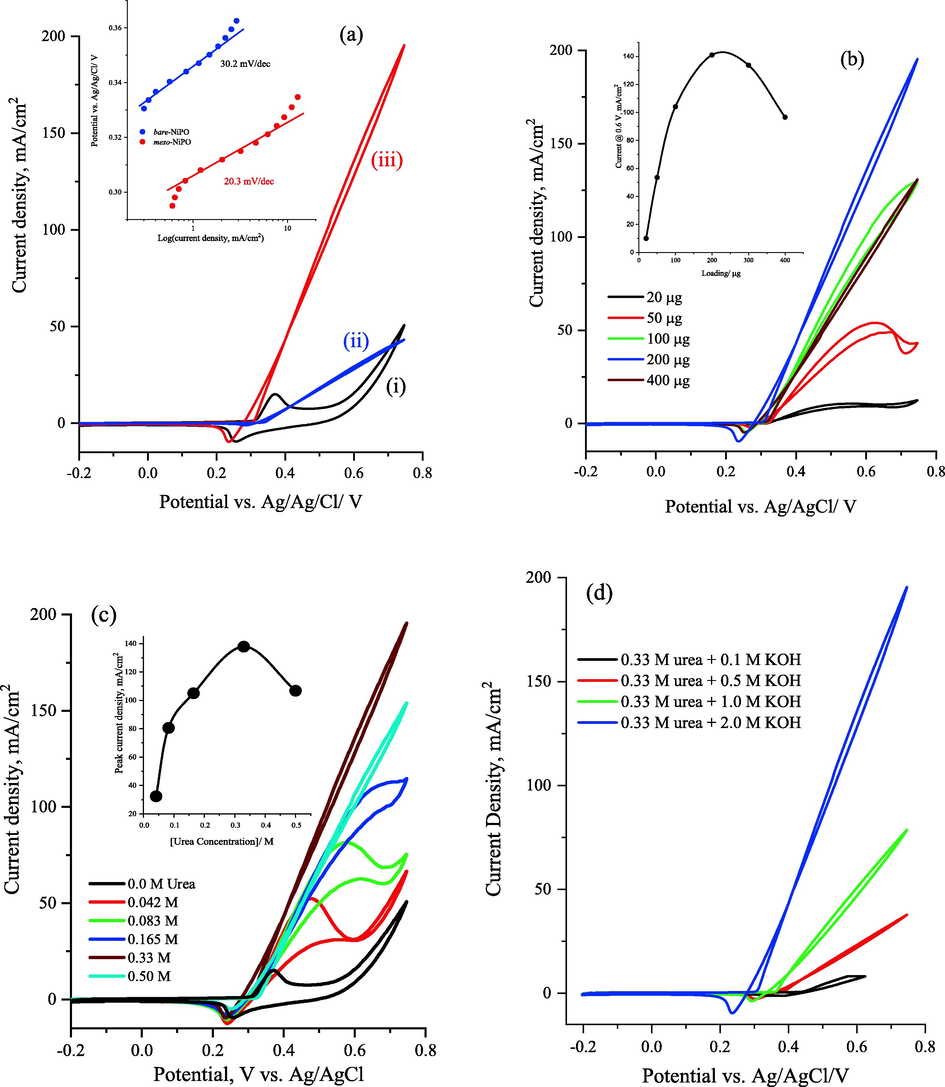
(a) cyclic voltammograms at 50 mV/s of 200 µg/cm2 of meso-NiPO in 2.0 M KOH (i) and in the presence of 0.33 M urea solution (iii) and compared with bare-NiPO (ii) catalyst; the inset shows the calculated Tafel slopes of both catalysts derived from polarization curve in Fig. 1a, (b) cyclic voltammograms at 50 mV/s for the effect of meso-NiPO catalyst loading in 2.0 M KOH containing 0.33 M urea, the inset is the relationship between catalyst loading and urea oxidation current at 0.6 V vs. Ag/AgCL, (c) presents the CVs of the meso-NiPO electrode in 2.0 M KOH containing different concentrations of urea at 50 mV/s, and the inset shows the relationship of the oxidation current density at 0.6 V vs. Ag/AgCl and the urea concentration in 2.0 M KOH solution, and (d) cyclic voltammograms of the meso-NiPO (200 µg/cm2) electrode at 50 mV/s in 0.33 M urea solution containing different concentrations of KOH.
Furthermore, Fig. 5b presents the CVs response of the meso-NiPO electrocatalyst at 50 mV/s in the 0.33 M urea at different catalyst loading from 20 to 400 µg, showing that the anodic urea oxidation current gradually increases with increasing the meso-NiPO electrocatalyst loading up to 200 µg due to the enhancement of Ni(II)/Ni(III) active sites for UOR (inset in Fig. 5b). However, the oxidation currents begin to saturate at higher loading of the meso-NiPO catalyst (>200 µg) because the film thickness increases and the limited accessibility and diffusion to the active sites.
Fig. 5c presents the CVs of the meso-NiPO electrode in 2.0 M KOH containing different concentrations of urea at 50 mV/s, showing that the oxidation currents of UOR significantly increase as the urea concentrations increase from 0.0 to 0.33 M, then the anodic current decreases at a higher urea concentration of 0.5 M, indicating that the electrochemical urea oxidation is a diffusion-controlled process at lower urea concentrations (below 0.33 M). Notably, as shown in the inset of Fig. 5c, the decrease of the urea oxidation current at a urea concentration greater than 0.33 M is possibly attributed to some kinetic limitations toward UOR due to the competitive adsorption of hydroxyl ions with urea molecules at the mesoporous Ni3(PO4)2 catalyst surface. Under alkaline conditions, the electrochemical oxidation of urea at nickel-based catalysts follows a catalyst-regeneration mechanism (an indirect electrochemical-chemical mechanism) as shown in Eqs. (3) to (5) (Hu et al., 2020; Al-Sharif et al., 2020; Klähn et al., 2004; Vedharathinam and Botte, 2012; Vedharathinam and Botte, 2013). The reaction mechanism pathways involved the electrooxidation of Ni(II) to Ni (III) by hydroxyl ions (Eq. (4)) within the nickel phosphate matrix, and then Ni(III)(OH)3 chemically reacts with urea. Notably, the urea completely oxidises and Ni(II) is re-generated (Eq. (4)) and the overall anodic reaction is shown in Eq. (5) (Al-Omair et al., 2017; Vedharathinam and Botte, 2013).
The N2 and CO2 gases are the main urea electrooxidation products using nickel-based catalysts. However, a recent work (Hopsort et al. 2023) reported the identification of various compounds such as cyanate, ammonium, carbonate and nitrite ions that are the main byproducts of urea electrooxidation using Ni(II)/Ni(III) redox catalyst. Moreover, Fig. 5d shows the CVs of meso-meso-NiPO nanoparticles (200 µg/cm2) at 50 mVs−1 in 0.33 M urea solution containing different concentrations of KOH. It can be seen a substantial negative shift of urea oxidation onset potential results from the Nernst effect of the increased hydroxide ion concentration (i.e. the UOR becomes thermodynamically more favourable). Moreover, when the hydroxide ion was increased from 0.1 to 2.0 M, the urea oxidation current was increased by more than fifteen times at a more positive potential. This can be credited to the factors of the acceleration of the anodic reaction shown in Eq. (3) and the increase of the ionic strength and active site accessibility of the high surface area mesoporous film.
Fig. 6a shows the long-term stability chronoamperometry (CA) at different catalyst loadings compared to the bare-NiPO electrode at an applied potential of 0.6 V vs. Ag/AgCl. The chronoamperograms of the meso-NiPO electrode exhibit a significantly higher urea steady-state oxidation current with increasing catalyst loading from 100 µg to 200 µg compared to the bare-NiPO electrode in 2.0 M KOH containing 0.33 M urea, which is attributed to more Ni(II)/Ni(III) active sites. Moreover, at the end of the 3-hour electrolysis, the meso-NiPO electrode had a higher current density (135.6 mA/cm2) and 97.5% of the urea oxidation in 2.0 M KOH was maintained than for the bare-NiPO catalyst (10.4 mA/cm2) at the same loading (200 µg), confirming the meso-NiPO catalyst is more active and stable for UOR in a basic solution. Furthermore, Fig. 6b presents the multi-cycle responses (100 cycles) of the meso-NiPO electrode in 0.33 M urea solution in 2.0 M KOH at 50 mVs−1, showing that the meso-NiPO catalyst displays extremely stable urea oxidation currents up to a potential of 0.70 V vs. Ag/AgCl within 100 cycles, thus superior stability for UOR in basic media.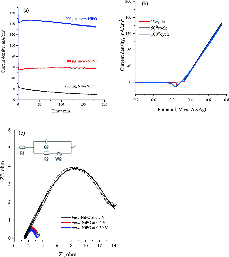
(a) chronoamperogramms for 3 h of meso-NiPO electrode with different loading and compared with bare-NiPO catalysts in 0.33 M urea/2.0 M KOH at the potential of 0.6 V vs. Ag/AgCl, (b) the multi-cycle responses (100 cycles) of the meso-NiPO electrode in 0.33 M urea solution in 2.0 M KOH at 50 mV/s and (c) Nyquist plot recorded for 200 µg/cm2 of the meso-NiPO catalyst and bare-NiPi at shown potentials and frequency of 100 kHz to 10 MHz in 2.0 M KOH containing 0.33 M urea, the inset show the equivalent circuit.
Fig. 6c provides the Nyquist plot recorded for 200 µg of meso-NiPO nanoparticles compared with bare-NiPO catalyst at various applied potentials in 0.33 M urea/ 2.0 M KOH. Table 1 reports the EIS parameters obtained within the fitting of impedance spectra for both meso-NiPO and bare-NiPO catalysts by a suitable equivalent circuit model (inset in Fig. 6c) that consisted of a parallel combination of (Q2) and (R2) elements at higher frequencies and Warburg diffusion element (Wde) is in a series with R2 (R2-W//Q2) that are in series with solution resistance (R1). The Q element that was used to fit the EIS results refers to the constant phase element which generally applies instead of the double-layer capacitor because of the surface inhomogeneity, porosity, roughness, and surface/normal distribution of the elements (Singh et al., 2015). The results of Nyquist plots the arc radii for the meso-NiPO electrode significantly decreased compared to bare-NiPO at the oxidation potential of 0.50 V vs. Ag/AgCl, suggesting the substantial improved UOR and faster charge transfer at the meso-NiPO electrode. As shown in Table 1 the the electrolyte resistance (R1) is practically constant at 1.48 O, whereas the urea oxidation charge transfer resistant (R2) value for the meso-NiPO catalyst is equals 3.85 and 3.35 O at applied potential of 0.40 and 0.50 V respectively, which is significantly lower than that of bare-NiPO electrode (16.30 Ω). The impedance results confirmed the charge transfer of urea electrooxidation is much faster at the mesoporous meso-NiPO than bare-NiPO catalyst which is consistent with CVs results.
Potential vs. Ag/AgCl/V
EIS parameters
R1, ohm
Q2, F.S(α -1)
R2, ohm
Winf, cm2/s
meso-NiPO, 0.50 V
1.329
0.341
3.35
0.076
meso-NiPO, 0.40 V
1.413
0.254
3.85
3.286 × 10⁻²
bare-NiPO, 0.5 V
1.519
0.027
16.3
0.538 × 10⁻³
Finally, Fig. 7 reveals the surface morphology and EDX elemental analysis of the meso-NiPO catalyst after being used for 3 h in the stability test during the electrolysis in 0.33 M urea/ 2.0 M KOH solution at 0.60 V vs. Ag/AgCl (Fig. 7a). Interestingly, the SEM image in Fig. 7a shows that the after use meso-NiPO catalyst maintains the surface morphology of burry fruit nanoparticles almost similar to the as-prepared mesoporous Ni3(PO4)2 nanoparticles (Fig. 2b). However, the EDX elemental analysis (Fig. 7b) reveals that the meso-NiPO elements wt. % composition changes after the catalyst was used in the stability test. The Ni content significantly decreased from 48.1 to 38.4 wt% and similarly, the P decreased from 12.4 to 6.69 wt%, whereas the oxygen content increased from 39.5 to 54.9 wt% after the meso-NiPO catalyst was oxidised during the stability test in an alkaline solution. This change in elemental composition is attributed to the meso-NiPO catalyst exposed to complex chemical and electrochemical reactions according to Eqs. (3) to (5) during the electrolysis process in 0.33 M urea/2.0 M KOH solution at 0.50 V vs. Ag/AgCl. Moreover, the N2 and CO2 gas products' evolution during urea electrolysis may cause mechanical leaching of the catalyst particles. Even though the meso-NiPO catalyst exhibits remarkable stability and maintained 97.5% of the urea steady-state oxidation current after the 3-hour stability test as shown in Fig. 4c. In addition, Table 2 reports the electrocatalytic activity of the meso-NiPO catalyst as compared and evaluated against the state-of-the-art nickel-based catalysts reported in the literature. The meso-NiPO catalyst demonstrated superior specific and mass electrocatalytic activity for urea oxidation in alkaline solution (141.4 mA/cm2, 700.7 mA/cm2 mg) than the reported nickel phosphate-based catalysts with different nanoarchitectures such as NiPO (30 mA/cm2, 600 mA/cm2 mg) (Song et al., 2017), NiCoPO nanosheets (65.4 mA/cm2) (Yang et al, 2019), and Ni3(PO4)2·8H2O (50 mA/cm2) (Al-Omair et al., 2017). However, the meso-NiPO catalyst showed lower specific activity than NiCo2O4 nanowire/NF (570 mA/cm2) (Sha et al., 2019), the nickel phosphate nanorods/NF (160 mA/cm2) (Tsai et al., 2020), and 3D porous NiO/NF (222 mA/cm2) (Zhang et al., 2019) presumably because the later catalysts are deposited hydrothermally onto high surface area nickel foam substrates and high concentration of KOH electrolyte.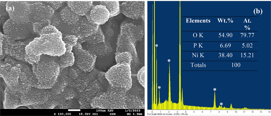
(a) SEM image and (b) EDX and elemental analysis of meso-NiPO after being used in a long-term stability test for 3 h in in 0.33 M urea/2.0 M KOH solution at an oxidation potential of 0.6 V vs. Ag/AgCl.
Anodic materials
Onset potential (V)
Stability (min.)
specific activity, mA/cm2,
(mass activity, mA/cm2 mg)Electrolyte
Ref.
meso-structure of NiPO
0.33 V vs. Ag/AgCl
∼17
30
(600) at 0.5 V0.10 M urea/
1.0 M KOH(Omar et al., 2016)
nickel phosphate nanorods
0.27 V vs. SCE
150
160
0.33 M urea/
1.0 KOH(Pujari et al., 2021)
NiCoPO nanosheets
0.22 V vs. Ag/AgCl
30
65.4
0.10 M urea/
1.0 KOH(Zhou et al., 2019)
Ni3(PO4)2·8H2O
0.45 V vs. Ag/AgCl
60
50
0.3 M urea/
0.5 KOH(Vedharathinam and Botte, 2013)
Ni-WC/MWCNT
0.43 V vs. Hg/HgO
–
46.4
0.33 M urea/
1.0 M KOH(Touny and Saleh, 2018)
NiCo2O4 nanowire/NF
0.19 V vs. Ag/AgCl
∼27
570
0.33 M urea/
5.0 M KOH(Song et al., 2017)
3D porous NiO/NF
0.48 vs. Ag/AgCl
222
0.1 M urea/ 8.0 M NaOH
(Zhang et al., 2019)
Mesoporous Ni3(PO4)2 nanoparticles
0.30 V vs. Ag/AgCl
180
141.4
(700.7) at 0.6 V0.33 M urea/2.0 M KOH
This work
Finally, the hydrogen evolution rate (HER) during urea electrolysis at meso-NiPO catalyst was further monitored in 2.0 M KOH and 0.33 M urea solution using an H-shape electrolyzer (shown in Fig. S4 in supporting materials) assembled with meso-NiPO anode (0.50 mg/cm2) and nickel foam as the cathode. Fig. 8 shows the cathodic hydrogen production rate at different applied potentials of 1.6, 1.8 and 2.0 V using 2.0 M KOH solution in the absence and presence of 0.33 M urea. The results show that in pure 2.0 M KOH solution and at an applied bias of 1.6 V, the rate of hydrogen generation at the cathode reaches about 38.5 µmol/h, while in the presence of 0.33 M urea, the hydrogen production rate has increased to about 100 µmol/h. This indicates that about 2.5 times more hydrogen production rate was obtained in the presence of urea. Moreover, the hydrogen production rate at the meso-NiPO anode was higher by more than four times compared to the bare-NiPO catalyst (about 23.0 µmol/h). As the applied potential further increases to 1.8 and 2.0 V, the rate of hydrogen evolution increases to 232 and 415 µmol/h respectively. The faradaic efficiency obtained using the meso-NiPO anode was found to equal 96.8%, indicating high energy efficiency and cheaper hydrogen green production using meso-NiPO catalyst and urea electrolysis.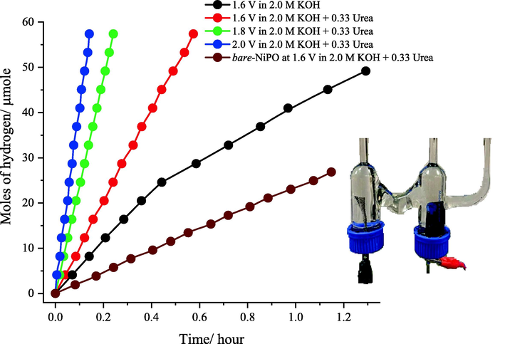
Plot of the cathodic hydrogen production rate obtained using an H-shape electrolyzer and meso-NiPO anode (loading 0.50 mg/cm2) compared to bare-NiPO at a different applied potential of 1.6, 1.8 and 2.0 V using 2.0 M KOH solution in the absence and presence of 0.33 M urea. The inset shows the H-shape electrolyzer assembled with meso-NiPO anode (0.50 mg/cm2) and nickel foam as a cathode.
4 Conclusion
The synthesis of meso-NiPO electrocatalyst using chemical deposition from a liquid crystal template has demonstrated great potential for enhancing the electro-oxidation of urea in alkaline solutions. Mesoporous nickel phosphate nanoparticles with a larger surface area and improved electrocatalytic performance for urea oxidation were prepared via simple chemical precipitation from the surfactant liquid crystal template media. The nickel ions dissolved in the aqueous domain of the hexagonal liquid crystalline phase of the Brij 78 template were reacted with sodium phosphate solution to precipitate the mesoporous nickel phosphate catalyst. The produced Ni3(PO4)2 nanoparticles are an amorphous and highly porous structure with a specific surface area of 43.50 m2/g and exhibit significantly enhanced electrocatalytic performance and stability towards UOR. As compared with bare-NiPO, the meso-NiPO electrode achieved mass activity of 700.7 mA/cm2 mg, lower oxidation onset potential (0.30 V vs. Ag/AgCl), and lower charge transfer resistance (3.35 Ω) at an oxidation potential of 0.6 V vs. Ag/AgCl. Using an H-shape urea electrolyser, the corresponding cathodic hydrogen Faradic efficiency was 96.8 % and the production rate reached 415 µmol/h at an applied bias of 2.0 V. The high-performance activity of the meso-NiPO catalyst is credited to the intrinsic large specific surface area and mesoporous architecture that provide more active sites, efficient charge transfer, as well as mass transport of the electroactive species. The room temperature chemical deposition from a surfactant liquid crystal template is a simple one-pot synthesis method that can be applied to precipitate a wide range of mesoporous inorganic catalysts for application in electrochemical energy catalytic reactions.
Acknowledgements
This project was funded by the National Plan for Science, Technology, and Innovation (MAARIFAH), King Abdulaziz City for Science and Technology, Kingdom of Saudi Arabia, Award Number 13-NAN-1309-02.
Declaration of Competing Interest
The authors declare that they have no known competing financial interests or personal relationships that could have appeared to influence the work reported in this paper.
References
- Reflux-based synthesis and electrocatalytic characteristics of nickel phosphate nanoparticles. J. Power Sources. 2017;342:1032-1039.
- [Google Scholar]
- Mesoporous cobalt phosphate electrocatalyst prepared using liquid crystal template for methanol oxidation reaction in alkaline solution. Arab. J. Chem.. 2020;13:2873-2882.
- [Google Scholar]
- Synthesis, characterization, electrochemistry, and in situ X-ray diffraction investigation of Ni3(PO4)2 as a negative electrode material for lithium-ion batteries. ChemElectroChem. 2020;15:3866-3873.
- [Google Scholar]
- Cost-effective and efficient water and urea oxidation catalysis using nickel-iron oxyhydroxide nanosheets synthesized by an ultrafast method. J. Colloid Interface Sci.. 2021;584:760-769.
- [Google Scholar]
- Ni & Mn nanoparticles decorated carbon nanofibers as effective electrocatalyst for urea oxidation. Appl. Catal. A. 2016;510:180-188.
- [Google Scholar]
- Urea electrolysis: direct hydrogen production from urine. Chem. Commun.. 2009;32:4859-4861.
- [Google Scholar]
- Earth-Abundant metal-based electrocatalysts promoted anodic reaction in hybrid water electrolysis for efficient hydrogen production: recent progress and perspectives. Adv. Energy Maters.. 2022;12:2201047.
- [Google Scholar]
- Facile synthesis of mesoporous spinel NiCo2O4 efficient electrocatalysts for urea electro-oxidation. Nanoscale. 2014;6:1369-1376.
- [Google Scholar]
- Mesoporous Ni-P nanocatalysts for alkaline urea electrooxidation. Electrochim. Acta. 2016;222:455-462.
- [Google Scholar]
- Mesoporous Ni-P nanocatalysts for alkaline urea electrooxidation. Electrochimica Acta.. 2016;222:455-462.
- [Google Scholar]
- Concurrent deposition and exfoliation of nickel hydroxide nanoflakes using liquid crystal template and their activity for urea electrooxidation in alkaline medium. Electrocatalysis. 2017;8:16-26.
- [Google Scholar]
- Electrocatalytic oxidation of ethanol using modified nickel phosphate nanoparticles and multi-walled carbon nanotubes paste electrode in alkaline media for fuel cell. Int. J. Hydrogen Energy. 2016;41:20085-20099.
- [Google Scholar]
- Progress toward a better understanding of the urea oxidation by electromediation of Ni(III)/Ni(II) system in alkaline media. Electrochim. Acta. 2023;442:141898
- [Google Scholar]
- Urea electrooxidation: current development and understanding of Ni-based catalysts. ChemElectroChem. 2020;7:3211-3228.
- [Google Scholar]
- IR spectra of phosphate ions in aqueous solution: predictions of a DFT/MM approach compared with observations. Chem. A Eur. J.. 2004;108:6186-6194.
- [Google Scholar]
- A review of hetero-structured Ni-based active catalysts for urea electrolysis. J. Mater. Chem. A. 2022;10:9308-9326.
- [Google Scholar]
- High-performance urea electrolysis towards less energy-intensive electrochemical hydrogen production using a bifunctional catalyst electrode. J. Mater. Chem. A. 2017;5:3208-3213.
- [Google Scholar]
- Enhanced electrocatalysis for energy-efficient hydrogen production over CoP catalyst with nonelectroactive Zn as a promoter. Adv. Energy Mater.. 2017;7:1-8.
- [Google Scholar]
- Hydrogen production technologies: from fossil fuels toward renewable sources: a mini review. Energy Fuels. 2021;35:16403-16415.
- [Google Scholar]
- Synthesis and characterization of Co-precipitated nickel phosphate [Ni3(PO4)2] nanoparticles prepared at varying precursor concentrations. J. Indian Chem. Soc.. 2023;20:101026
- [Google Scholar]
- Ultrahigh capacitance of amorphous nickel phosphate for asymmetric supercapacitor applications. RSC Adv.. 2016;6:76298-76306.
- [Google Scholar]
- Enhancing rate capability of amorphous nickel phosphate supercapacitance electrode via composition with crystalline silver phosphate. Electrochim. Acta. 2018;273:216-228.
- [Google Scholar]
- Highly sensitive hydrothermally prepared nickel phosphate electrocatalyst as non-enzymatic glucose sensing electrode. J. Porous Mater.. 2021;28:369-381.
- [Google Scholar]
- Novel bifunctional V2O3 nanosheets coupled with N-doped-carbon encapsulated Ni heterostructure for enhanced electrocatalytic oxidation of urea-rich wastewater. ACS Appl. Mater. Interfaces.. 2020;12:38061-38069.
- [Google Scholar]
- Synthesis of X3(PO4)2 [X = Ni, Cu, Mn] nanomaterials as an efficient electrode for energy storage applications. J. Nanosci. Nanotechnol.. 2020;20:2813-2822.
- [Google Scholar]
- Hierarchical NiCo2O4 nanowire array supported on Ni foam for efficient urea electrooxidation in alkaline medium. J. Power Sources. 2019;412:265-271.
- [Google Scholar]
- Strongly coupled carbon encapsulated Ni-WO2 hybrids as efficient catalysts for water-to-hydrogen conversion via urea electro-oxidation. J. Power Sources. 2020;458:228014
- [Google Scholar]
- Reporting physisorption data for gas/solid systems with special reference to the determination of surface area and porosity. Pure Appl. Chem.. 1985;57:603-619.
- [Google Scholar]
- Electrochemical impedance spectroscopy of oxygen reduction reaction (ORR) in a rotating disk electrode configuration: effect of ionomer content and carbon-support. J. Electrochem. Soc.. 2015;162:F489-F498.
- [Google Scholar]
- Nickel phosphate-based materials with excellent durability for urea electro-oxidation. Electrochim. Acta. 2017;251:284-292.
- [Google Scholar]
- Efficient hydrogen production via urea electrolysis with cobalt doped nickel hydroxide-riched hybrid films: Cobalt doping effect and mechanism aspect. J. Catal.. 2020;381:454-461.
- [Google Scholar]
- Rh-engineered ultrathin NiFe-LDH nanosheets enable highly-efficient overall water splitting and urea electrolysis. Appl. Catal. B Environ.. 2021;284:119740
- [Google Scholar]
- Enhanced methanol oxidation on nanoporous nickel phosphate modified platinum electrode in alkaline solution. Int. J. Electrochem. Sci.. 2018;13:1042-1050.
- [CrossRef] [Google Scholar]
- Zeolitic nickel phosphate nanorods with open-framework structure (VSB-5) for catalytic application in electro-oxidation of urea. Appl. Surf. Sci.. 2020;529:147175
- [Google Scholar]
- Understanding the electro-catalytic oxidation mechanism of urea on nickel electrodes in alkaline medium. Electrochim. Acta. 2012;81:292-300.
- [Google Scholar]
- Direct evidence of the mechanism for the electro-oxidation of urea on Ni(OH)2 catalyst in alkaline medium. Electrochim. Acta. 2013;108:660-665.
- [Google Scholar]
- Nickel/nickel oxide nanocrystal nitrogen-doped carbon composites as efficient electrocatalysts for urea oxidation. J. Alloys Compounds. 2021;870:159408
- [CrossRef] [Google Scholar]
- Nanostructured β−NiS catalyst for enhanced and stable electro−oxidation of urea. Catalysts. 2020;10:1-11.
- [Google Scholar]
- Bimetallic NiCoP nanosheets array for high-performance urea electro-oxidation and less energy-intensive electrolytic hydrogen production. ChemistrySelect. 2017;2:10285-10289.
- [Google Scholar]
- Partially amorphous nickel-iron layered double hydroxide nanosheet arrays for robust bifunctional electrocatalysis. J. Mater. Chem. A. 2018;6:16121-16129.
- [Google Scholar]
- Electrochemical decomposition of urea with Ni-based catalysts. Appl Catal B. 2012;127:221-226.
- [Google Scholar]
- Nickel nanowires as effective catalysts for urea electro-oxidation. Electrochim. Acta. 2014;134:266-271.
- [Google Scholar]
- Nickel phosphate materials regulated by doping cobalt for urea and methanol electro-oxidation. Int. J. Hydrogen Energy. 2019;44:16305-16314.
- [Google Scholar]
- Highly porous nickel@carbon sponge as a novel type of three-dimensional anode with low cost for high catalytic performance of urea electro-oxidation in alkaline medium. J. Power Sources. 2015;283:408-415.
- [Google Scholar]
- Recent advances in the electro-oxidation of urea for direct urea fuel cell and urea electrolysis. Top. Curr. Chem.. 2018;376:1-38.
- [Google Scholar]
- Novel Ni foam-based nickel oxalate-derived porous NiO nanostructures as highly efficient electrodes for the electrooxidation of methanol/ethanol and urea. J. Alloys and Compounds. 2019;806:1419-1429.
- [Google Scholar]
- Chemical precipitation synthesis of porous Ni2P2O7 nanowires for supercapacitor. J. Alloy. Compd.. 2019;790:36-41.
- [Google Scholar]
- Zhu, B., Liang, Z., Zou, R., 2020. Designing advanced catalysts for energy conversion based on urea oxidation reaction. Small. 16, 1906133 (1–19).
Appendix A
Supplementary material
Supplementary data to this article can be found online at https://doi.org/10.1016/j.arabjc.2023.105266.
Appendix A
Supplementary material
The following are the Supplementary data to this article:Supplementary data 1
Supplementary data 1


