

Translate this page into:
Calculation method for the dielectric constant of thioglycolic acid grafted modified SBS dielectric elastomer
⁎Corresponding author at: No.174 Shazhengjie, Shapingba, Chongqing 400044, People’s Republic of China. zhx.zhang@cqu.edu.cn (Zhanxi Zhang)
-
Received: ,
Accepted: ,
This article was originally published by Elsevier and was migrated to Scientific Scholar after the change of Publisher.
Abstract
Nonpolar/polar block copolymer materials can be used to develop high-performance dielectric elastomer materials. At present, there is no method to accurately predict its dielectric constant, which is not conducive to improving related research and development efficiency. For this, styrene–butadienestyrene triblock copolymer (SBS) block copolymer grafted modified by thioglycolic acid (TGA) is chosen as the research object. We propose a hybrid calculation method combining the group contribution method, the connectivity index method, and the dipole moment fluctuation method. The connectivity index method and the dipole moment fluctuation method calculate the dielectric constants of nonpolar and polar repeat units to provide accurate basic data for the group contribution method. In the calculation process, the Vogel model completes the mutual conversion between dielectric constant and molar polarizability. Both theoretical calculation and experimental verification show that the dielectric constant of SBS-TGA increases with the grafting rate. We found the correlation between theoretical calculations and experimental values and confirmed that the applicable frequency range of this method is 1 kHz–1000 kHz. This method can be extended to predict the dielectric constant of other polymers and improve development efficiency.
Keywords
Dielectric constant
Modified SBS
Group contribution
Connectivity index
Dipole moment fluctuation

1 Introduction
Dielectric Elastomer (DE) has a large strain, high energy density, and fast response speed. It has crucial application potential in flexible electronic equipment such as artificial muscles, implantable biological electronic devices, micro energy harvesting, sensors, etc. (Brochu and Pei, 2010; Madsen et al., 2016a,b; Pelrine et al., 2000).
From Eq. (1) for evaluating the electromechanical properties of the material, it can be seen that the dielectric constant is one of the essential factors that determine the properties of DE materials(Pelrine et al., 1998; Molberg et al., 2009; Kussmaul et al., 2011). For DE materials with the same Young’s modulus, the greater the dielectric constant, the stronger the energy conversion ability(Koh et al., 2009; Lv et al., 2015; Han et al., 2020).
where Sz is the strain in the thickness direction of the DE material under the action of the electric field, Y is the elastic modulus of the material, P is the Maxwell force, ε0 is the vacuum dielectric constant, εr is the relative dielectric constant, and E is electric field strength acting on the material.
At present, modified or synthesized block copolymers are often used to develop high-performance dielectric elastomer materials (Chen et al., 2021; Ma et al., 2017; Tian et al., 2016; Zhao et al., 2018a,b). For example, the overall electromechanical performance of modified SBS has been significantly improved after being grafted and modified with polar groups, such as thioglycolic acid and methyl thioglycolate (Gress et al., 2007; Sun et al., 2016; Ellingford et al., 2018). Screening suitable polar groups are of great significance to the development of new SBS-based dielectric elastomers. The traditional “synthesis then test” screening method is time-consuming and costly. Computer-aided calculation of the dielectric constant of modified SBS can improve the efficiency of research and development (Frühbeis et al., 1987; Satyanarayana et al., 2009; Holtje, 2011), such as group contribution (GC) method, connectivity index (CI) method, and dipole moment fluctuation (DMF) method.
GC method is a classic structure–property analysis method (Vankrevelen and Hoftyzer, 1969; Martin, 1981). In recent years, there are still developments and applications in refractive index (Gharagheizi et al., 2014), heat capacity (Walker and Haslam, 2020), atmospheric lifetime (Eini et al., 2020), etc. The same group shows the same contribution to certain characteristics of different molecules is the theoretical basis of this method (Vankrevelen and Hoftyzer, 1969; Krevelen, 1990; Bicerano, 1992). The polymer molecular chain is divided into different repeating units, and the dielectric constant of the polymer can be accurately calculated according to the contribution value of each repeating unit (Bicerano, 2002; Zhou et al., 2014). Gladston-Dale model (Gladstone and Dale, 1858), Lorentz-Lorenz model (Lorenz, 1880; Ha, 1880; Zhou et al., 2014), Vogel model (Vogel, 1948), etc., as shown in Eqs. (2)–(4) are often used. The first two models have a good theoretical explanation, and the Vogel model is a simple empirical formula. The three models have the same standard deviation (Van Krevelen Willem and Nijenhuis, 1976). This method cannot be used without the group contribution value of any repeating unit, and the need for complete experimental data as support is its obvious disadvantage (Katritzky et al., 1998).
The CI method is a structure–property analysis method developed based on chemical graph theory (Kier and Hall, 1976a,b, 1986). In recent years, there are still developments and applications in the carcinogenicity prediction of substances (Li et al., 2019), drug agonistic activity analysis (Raghuraj et al., 2020), and quantitative structure–activity relationship modeling (Zakharov et al., 2019; Song et al., 2020). The principle is the correlation between the connectivity index calculated accurately based on the valence bond structure and the properties of interest (Kier and Hall, 1976a,b, 1986). The CI method is simple to calculate and does not require experimental data support, and can accurately predict the permittivity of many nonpolar polymers (Polak and Sundahl, 1989; Camarda and Maranas, 1999). The applicable frequency range of the CI method is optical frequency, and the only induced polarization of nonpolar polymers under the action of an electric field occurs in this frequency range (Mossotti, 1847), so the connectivity index can be used to calculate the dielectric constant (Kier and Hall, 1976a,b, 1986) accurately. However, under the action of an electric field, polar molecules have two processes of induced polarization and orientation polarization. Their molecular polarization is shown in Eq. (5) (Mossotti, 1847), and the relationship between molecular polarization and dielectric constant is shown in Eq. (6) (Clausius, 1879; Böttcher, 1973). The frequency range corresponding to orientation polarization is lower, making the CI method unable to calculate the dielectric constant of polar molecules accurately.
The DMF method is a calculation method of dielectric properties based on molecular dynamics (Williams, 1972; De Leeuw et al., 1980; Neumann, 1983; Adams and Adams, 2006). In recent years, there still are developments and applications in the analysis of the permittivity of supercritical water (Hou et al., 2020) and organic semiconductors (Sami et al., 2020), and the analysis of dielectric relaxation of crystals (Mattoni and Caddeo, 2020). The calculation principle is the relationship between the dipole moment–time correlation function and the macroscopic complex permittivity derived from molecular theory(Williams, 1972). At present, the research objects of the DMF method are mainly small molecules and low polymerization degree polymers (Anderson et al., 1987; Skaf, 1997; Smith et al., 2002). The DMF method is often used in the analysis of material induce polarization, but the commonly used fixed force field(Jorgensen et al., 1996; Chen and Siepmann, 1999; Huang et al., 2017) is not effective in dealing with the dielectric constant calculation of nonpolar molecules, such as benzene. The value and the experimental values are 1.005 (Cardona et al., 2020) and 2.25 (Mardolcar et al., 1992), respectively. The orientation polarizability that dominates the molecular polarizability of polar materials can be accurately estimated by molecular dynamics (Cardona et al., 2020). Therefore, the DMF method to calculate the dielectric constant is mainly suitable for small molecule polar systems (Neumann, 1983; Anderson et al., 1987; Skaf, 1997).
The SBS molecular chain modified by polar groups contains both nonpolar and polar repeating units. The complementary advantages of the CI method and DMF method can accurately calculate the dielectric constant of all repeating units. Therefore, this paper uses the CI method and DMF method to calculate the dielectric constants of nonpolar and polar repeating units, respectively, to provide accurate basic data for the GC method, and form a hybrid calculation method suitable for the calculation of the dielectric constant of grafted modified SBS. The theoretical calculation of SBS-TGA is consistent with the experimental measurement results, and the deviation between the two can be corrected by adjusting the fitting parameters.
2 Calculation method
2.1 Division of repeating units
Many synthetic macromolecular materials have relatively simple structures, and identical structures that recur in the molecular chain are defined as repeating units. If the repeating units are the same, the material is a homopolymer. If there are more than two repeating units, the material is a copolymer. Polymer molecular chains consist of a “backbone” and peripheral atoms or groups. The end groups in finite-size polymer chains are not repeating units and have little effect on the physical properties and are usually not considered.
The polymer molecular chain is divided into repeating units by searching for recurring identical structures along with the polymer' skeleton'. For subsequent analysis, the repeating units containing polar functional groups such as carboxylic acids, alcohols, amides, thiols, and ketones are classified as polar groups. Those containing only nonpolar functional groups such as alkanes and alkenes are classified as nonpolar groups.
The molecular structure of SBS-TGA is shown in Fig. 1a and can be divided into six repeating units, St, Cis-1,4-Bu, Trans-1,4-Bu, 1,2-Bu, 1,4-Bu-TGA, and 1,2-Bu-TGA(Segre et al., 1975; Kussmaul et al., 2011), denoted by G1,G2…G6, respectively, as shown in Fig. 1b. G1, G2, G3, and G4 are classified as nonpolar sets, and G5 and G6 are classified as polar sets.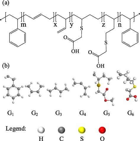
(a) The molecular structure of SBS-TGA, (b) the repeating units G1-G6: St, Cis-1,4-Bu, Trans-1,4-Bu, 1,2-Bu, 1,4-Bu-TGA, 1,2-Bu- TGA.
2.2 Calculation of dielectric constant of the nonpolar repeating unit
2.2.1 Calculation of connectivity index
For the nonpolar repeating unit Gi, the dielectric constant εi is calculated using the CI method. First, the hydrogen-suppressed graph is constructed from the valence bond diagram of the repeating unit, as shown in Fig. 2a and Fig. 2b, taking G1 as an example.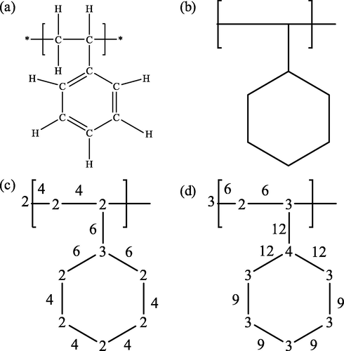
(a) The valence-bond structure of G1, (b) The hydrogen-suppressed graph of G1; (c) The δ value on the vertex and the β value on the edge; (d) The δV value on the vertex and the βV value on the edge.
The atomic indices δ and δV describe the electronic environment and the bond configuration of each non-hydrogen atom in the molecule. δ is the simple connectivity index and is equal to the number of edges emanating from that vertex in the hidden hydrogen diagram. δV is the valence connectivity index and is defined by Eq. (7) (Randic, 2015). The calculation results are shown in Fig. 2c and the values at the vertices in Fig. 2d.
The value corresponding to each bond that does not involve a hydrogen atom is defined as the bond index, and the bond index β and βV are determined by the product of the atomic indices (δ and δV) at the two vertices (i and j) connected by the edges, as shown in Eqs. (8) and (9). Taking G1 as an example, the calculation results are marked on the edges of the hydrogen-suppressed graph in Fig. 2c and Fig. 2d
The zero-order connectivity index (0χ, 0χV) of the whole molecule and is defined based on the atomic index of all vertices of the hydrogen-suppressed graph, as shown in Eqs. (10) and (11) (Randic, 1975). Taking G1 as an example, the results are calculated as 5.397 and 4.671, respectively.
The first-order connectivity index (1χ, 1χV) of the whole molecule is defined based on the bond index on all edges of the hydrogen-suppressed graph, as shown in Eqs. (12) and (13) (Randic, 1975). Taking G1 as an example, the results are calculated as 3.966 and 3.015, respectively.
The zero-order and first-order connectivity indexes of G1-G4 are shown in Table 1. For computational simplicity, this paper does not use higher-order connectivity indexes (Kier and Hall, 1976a,b), and various types of structural parameters are used to supplement the zero- and first-order connectivity indexes.
Repeating units
0χ
0χV
1χ
1χV
G1
5.397
4.671
3.966
3.015
G2
2.828
2.568
2.000
1.649
G3
2.828
2.568
2.000
1.649
G4
2.991
2.568
1.931
1.558
2.2.2 Calculation of dielectric constant
Based on the study of Darby, J R et al. (Darby et al., 1967), Bicerano proposed an improved metric method for calculating the dielectric constant of nonpolar repetitive cells (Bicerano, 2002), as shown in Eq. (14).
It should be noted that to ensure the generality of the calculation method, Eqs. (14)–(20) contain a large number of structural correction terms (Bicerano, 2002). If a specific structure does not exist in the polymer, the corresponding correction parameter is equal to zero. For example, when calculating Ecoh1 for G1, Natomic = 0 in Eq. (15).
The results of the dielectric constant calculations for G1-G4 are shown in Table 2. It can be seen from the table that the dielectric constants of the repeating units calculated by the CI method are very close to the measured values of their corresponding homopolymers, indicating that the calculation results of this method are accurate and can well characterize the contribution of nonpolar repeating units to the polymer as a whole.
No.
Molar mass
Calculated value
Tested value
G1
106.168
2.567
2.60(Deby and Bueche, 1951)
G2
56.108
2.317
–
G3
56.108
2.317
2.36(Chen, 1971)
G4
56.108
2.311
–
2.3 Calculation of the dielectric constant of the polar repeating unit
The dielectric constants of the polar repeating units (G5, G6) cannot be calculated by the structure–property analysis method. Molecular dynamics simulations (MDS) based on first principles can predict them (Bicerano, 2002). In this paper, the MDS of polar repeating units are used to calculate their dielectric constants using the DMF method.
A permanent molecular dipole consisting of two charge ± q at a distance l, giving the dipole moment μ = ql, is shown in Fig. 3. For molecules with complex structures, the dipole moment can be obtained by adding simple dipole moment vectors, as shown in Eq. (21). Similarly, it can be known that the total dipole moment M in a periodic cell is the vector sum of the dipole moments of all molecules in the system.
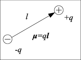
The schematic representation of a permanent molecular dipole.
An all-atom model of repeating unit is constructed in the Materials Studio software. On this basis, a periodic cell containing N particles is built for MDS (N = 256 (Neumann, 1983)), as shown in Fig. 4. In order to prevent the nesting of molecular structure, we set the initial density to be relatively low, 0.5 g/cm3. The reaction force field is COMPASS. The temperature control method is Andersen’s algorithm. The pressure control method is Berendsen’s, and the calculation of the non-bonded cooperative force is based on the group-based method. The simulation time step is 1 fs, the cutoff distance is 12.5 Å, the spline width is 1 Å, the buffer width is 0.5 Å, and the pressure is 0.1 MPa.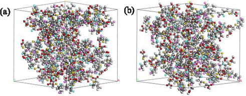
(a) G5′s and (b) G6′s periodic cell model.
The periodic cells are geometrically optimized with a convergence standard of 0.001 kcal/mol. The geometrically optimized periodic cells are annealed to make their density close to the real value. The annealing process is carried out in the NPT ensemble with a starting temperature of 300 K, an intermediate maximum temperature of 500 K, and a pressure value of 0.1 MPa. The temperature rise step is set to 50 K, and the number of cycles is 5. 100 000 kinetic steps are performed for each temperature, and one frame of output is performed every 500 steps.
On the basis of a stable conformation, 10 frames with a temperature of 298 K are extracted for NVT dynamics simulation with 400 ps, and the output frame is performed every 100 steps. The dielectric constant values of 10 samples are averaged as the final value to reduce the error. The total dipole moment of the system in each frame was statistically calculated using a Perl script. The total dipole moment M, as a vector, has three components Mx, My, and Mz in the ×, y, and z directions.
According to molecular theory, the corresponding relationship between dipole moment–time and macroscopic dielectric constant can be constructed (Williams, 1972). For periodic boundary systems, the relationship between total dipole moment–time and macroscopic dielectric constant can be expressed by Eq. (22) (De Leeuw et al., 1980; Heinz et al., 2001).
Each output frame of results during the simulation can be interpreted as a sampling of the dynamics simulation system, and Eqs. (23) and (24) can express the Boltzmann averaging term in Eq. (22).
To investigate the relationship between the dipole moment fluctuation of the repeating unit and the orientation polarization of the material, we calculated the dielectric constant values for different dipole moment fluctuation times, as shown in Fig. 5. Overall, G6 has a larger dielectric constant than G5, which is caused by the difference in permanent dipole moment μ0 due to the structural difference. As time increases, the dielectric constant of both G5 and G6 first increase and then decrease. This can be explained by the dielectric orientation polarization process. We assume that the different dipole moment fluctuation times correspond to the time of electric field action, as shown by the blue dashed line in Fig. 5. At the electric field value greater than zero, the dipole inside the material undergoes an oriented arrangement, and the polarization intensity is always intensified. The polarization intensity reaches its highest, and the dielectric constant is maximum when the dipole moment fluctuation time is 300 ps. When the electric field direction is flipped, the dipole arrangement inside the material will reverse with the electric field direction. If the statistical time exceeds 300 ps, the statistical result of Eq. (22) decreases, as shown in the figure for 350 ps, 390 ps, and 400 ps. This phenomenon may correspond to the phenomenon of internal polarization of the material under the action of an alternating electric field. Suppose an alternating electric field of voltage amplitude V acts on the material. When the electric field is positive, the polarization intensity inside the material gradually increases. When the electric field is negative, the dipole arrangement inside the material will turn, and the dielectric constant decreases. We intercepted the total dipole moment fluctuation data of G6 from 300 ps to 400 ps and calculated the dielectric constant as 6.78 using Eq. (22), which is very close to the result of t = 100 ps, which is consistent with our proposed conjecture.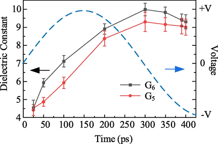
The dielectric constant of G5 and G6 with different simulation times.
2.4 Calculation of dielectric constant of graft-modified SBS
The molar polarizability of the repeating unit can be calculated using three models, Gladston-Dale, Lorentz-Lorenz, and Vogel, and considering that the molar mass is easier to calculate than the molar volume, the Vogel model is used in this paper. The results calculated according to Eq. (25) are shown in Table 3.
No.
G1
G2
G3
G4
Molar polarizability
170.101
85.092
85.092
85.295
No.
G5-300ps
G5-200ps
G5-100ps
G5-50ps
G5-25ps
Molar polarizability
452.036
±12.879428.922
±6.874360.749
±9.500327.051
±8.397314.799
±10.468
No.
G6-300ps
G6-200ps
G6-100ps
G6-50ps
G6-25ps
Molar polarizability
468.427
±8.090442.461
±7.175395.500
±8.749360.939
±7.213315.682
±11.483
In a semi-empirical approach, the molar properties of non-interacting substances can be calculated by summing the contributions of atoms, groups, or bonds (Zhou et al., 2014). The molar mass, molar polarizability of polymers can be calculated according to Eqs. (26)–(27).
Eqs. (26)–(27) are substituted into Eq. (4) yields Eq. (28) for the calculation of the dielectric constant of the polymer. Dividing the upper and lower parts of this equation simultaneously by ∑ni the Eq. (29) for calculating the dielectric constant of the polymer expressed in terms of molar content is obtained. The molar content was calculated by equation (30) (Tashiro et al., 1984).
SBS determines the molar content of each repeating unit in SBS-TGA. According to Fig. 1, the molar content of G1 is equal to that in SBS; G5 is derived from G2 and G3 grafted TGA. The sum of the three is equal to the sum of the molar content of G2 and G3 in SBS, and G6 is derived from G4 grafted TGA, and the sum of the molar content of the two is equal to the molar content of G4 in SBS. The C = C located in the side chain is more active and more prone to grafting reactions (Tian et al., 2016; Sun et al., 2016). Therefore, G4 reacts with TGA first during the grafting process. G2 and G3 do not graft TGA until G4 is completely converted to G6 and no G5 is generated. The relationship between c1-c6 in SBS-TGA can be written and expressed as Eq. (31).
According to SBS's H Nuclear Magnetic Resonance (HNMR) (Ellingford et al., 2018) and specific area analysis method c1,SBS = 18%,c2,SBS + c3,SBS = 60%,c4,SBS = 22%.
The variation of G5 and G6 molar content in SBS-TGA corresponds to the variation of TGA grafting rate in polybutadiene blocks. Therefore, the equation for the grafting rate of SBS-TGA is shown in Eq. (32), and the variation law of dielectric constant with grafting rate is shown in Fig. 6.
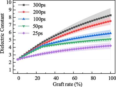
Calculated value of the dielectric constant of SBS-MT with different grafting rate.
It can be seen from the figure that the constant dielectric increases gradually with the increase of the grafting rate. The dielectric constant of unmodified SBS is 2.4 when the grafting rate is 0. Under the same polarization time, the higher the grafting rate, the greater the dielectric constant, and the maximum value can reach 8.3, which is 3.5 times the initial value. Therefore, for SBS-TGA, increasing its dielectric constant can be achieved by changing the reaction conditions to increase the grafting rate of TGA.
3 Experimental validation
3.1 Materials
SBS (YH-806) is produced by Baling Petrochemical, China, Tetrahydrofuran (THF, AR grade) and Cyclohexane (AR grade) are purchased from Kelon Chemical Co., Ltd., China, 2,2- dimethoxy-2 -phenyl acetophenone (DMPA, 99%) and TGA (AR grade, 96%) were purchased from Shanghai Aladdin Biochemical Technology Co., Ltd., China. All of the above chemicals were not processed before use.
3.2 Synthesis
The reaction principle was mercapto-olefin reaction under UV irradiation, and the catalyst was DMPA. The molar ratio of the sulfhydryl group to the C = C bond was set to 5:1 during the synthesis.
In the first step, SBS and tetrahydrofuran were placed in a beaker at the ratio of 1:9 by weight and stirred magnetically at 30 ℃ until SBS was dissolved entirely, and 50 g of the dissolution solution was used for material preparation. In the second step, 0.1 g of DMPA and 29.9 g of TGA were added to the SBS dissolution solution. Finally, the SBS-TGA was extracted from the solution with cyclohexane, filtered, and dried under vacuum at 60 ℃ for 24 h. The grafting rate of the SBS-TGA was determined by the use of a UV lamp with a wavelength of 365 nm and a power of 50 W. In the third step, the SBS-TGA was extracted from the solution with cyclohexane, filtered, and dried under vacuum for 24 h at 60 ℃.
3.3 Film sample preparation
The samples were prepared using a manual hot press machine model AR1701 from AUPLEX Co., Ltd., China. The raw material was placed in the mold at 150 °C and kept under normal pressure for 15 min to eliminate air bubbles, and the pressure was adjusted to 2.5 MPa and kept for 10 min. The mold was removed, cooled to room temperature, and then the film samples were taken out with a thickness of about 0.5 mm.
3.4 Calculation of grafting rate
The HNMR spectrum was measured using a Bruker AV600MHz high-resolution liquid NMR spectrometer with a solvent of CDCl3 and a chemical shift range of 0–8 ppm. The test results are shown in Fig. 7.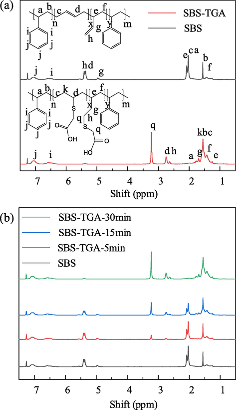
HNMR of SBS and SBS-TGA, (a) Chemical shifts of hydrogen atoms on the main functional groups, (b) HNMR of SBS-TGA with different grafting rates.
It can be seen from the figure that the characteristic peaks corresponding to C = C gradually decreased, and the characteristic peaks associated with TGA gradually increased with the increase of reaction time, which indicated that the grafting rate of SBS-TGA gradually increased. The area integrals of the characteristic peaks of the G1-G6 repeat units were calculated on the HNMR spectra with the benzene ring H as the reference, and the grafting rate of SBS-TGA could be calculated using the specific area method as shown in Eq. (33). The calculated results showed that the grafting rates of the three SBS-TGA samples were 15.3%, 47.2%, and 89.7%, respectively. The grafting rate gradually increased with the increase of reaction time.
3.5 Dielectric constant test
Measurements were performed using a Concept 80 broadband dielectric test system with an electrode diameter of 20 mm. The polarization ability of the material was enhanced after grafting dipole, and the dipole polarization time range was 10-10-10-2 s, corresponding to a frequency range of 102-1010 Hz, and considering the measurement range of the equipment, the test frequency range of 102-106 Hz was chosen in this paper. The variation curve of the real part of the dielectric constant with frequency is shown in Fig. 8.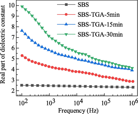
The real part of the dielectric constant of SBS and SBS-TGA.
The dielectric constant of SBS is basically not affected by frequency. This is because SBS is nonpolar, and the polarization phenomenon under the action of an electric field is mainly induced polarization, and the molecular polarization rate does not change within the measurement frequency range. The dielectric constant of SBS-TGA will gradually increase as the measurement frequency decreases. According to Eq. (5) and related analysis, the lower the frequency, the longer the electric field action time, the more orderly arrangement of the dipoles, and the greater the polarization intensity, which corresponds to a greater dielectric constant. The dielectric constant of SBS-TGA gradually increases with the increase of grafting rate. This is because the permanent dipole μ0 inside the material increases after grafting TGA. According to Eq. (5), the higher the grafting rate, the greater the polarization intensity at the same test frequency and the greater the dielectric constant. The difference in the dielectric constant of SBS-TGA with different grafting rates decreases as the frequency increases. This is because higher frequency means shorter dipole turning time and lower molecular polarizability. This leads to a decrease in the difference in the dielectric constant of SBS-TGA materials with different grafting rates.
3.6 Analysis of results
We choose five sets of data for comparison, as shown in Fig. 9. The experimental test values are selected at 0.1 kHz, 1 kHz, 10 kHz, 100 kHz, 1000 kHz, and the dipole moment fluctuation times are selected at 300 ps, 200 ps, 100 ps, 50 ps, and 25 ps, respectively. The difference between the test value at 0.1 kHz and the calculated value of 300 ps is very large for the first set of data, and the reason for this phenomenon is put in the following paragraphs. We can summarize the relationship between the test frequency and the dipole moment fluctuation time by using Eq. (34).
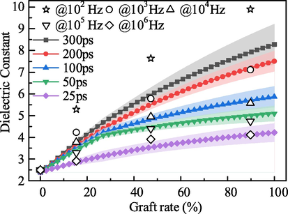
Comparison of experimental value and calculated value for dielectric constant.
We take the DMF time t1 = 45 ps, t2 = 150 ps, and t3 = 300 ps into Eq. (34) respectively, and calculate the corresponding frequency values f1 = 141.9 kHz, f2 = 2.6 kHz, f3 = 0.26 kHz. The calculated and measured dielectric constant of different samples is shown in Table 4.
SBS-TGA
Example 1
Example 2
Example 3
t1
f1
t2
f2
t3
f3
5 min
3.14
3.23
3.48
3.61
7.98
8.92
15 min
4.04
4.28
4.94
4.72
5.96
6.63
30 min
4.63
4.64
6.03
5.25
3.74
4.71
Examples 1 and 2 demonstrate that the theoretical calculations match the measured values relatively well in the higher frequency range, 1 kHz-1000 kHz. Example 3 shows that when the frequency is below 1 kHz, there is a significant deviation between the theoretical calculation and the measured value. At below 1 kHz, space charge polarization may occur within the material in addition to dipole shifting polarization, which further increases the overall material polarization intensity and results in larger measured dielectric constant values. The DMF method cannot take into account the space charge polarization process, so the proposed dielectric constant calculation method in this paper cannot perform dielectric constant prediction below 1 kHz. The applicability of the method in the higher frequency range has not been verified due to the measurement error of the experimental equipment and the accuracy of the software calculation. Therefore, the proposed method for calculating the dielectric constant of block copolymers is applicable in the frequency range of 1 kHz to 1000 kHz.
4 Conclusion
In this paper, a method for calculating the permittivity of nonpolar/polar block copolymers was proposed using SBS-TGA as the research object, and theoretical calculations and experimental tests proved the validity of the method. The main conclusions are as follows.
-
Based on the group contribution theory, the modified SBS molecular chains were split, and the group contribution values of nonpolar repeating units and polar repeating units were calculated using the CI method, the DMF method and Vogel model, and a hybrid calculation method of dielectric constants of block copolymers without relying on experimental data was proposed.
-
The grafting rate of polar groups can adjust the dielectric constant value of modified SBS. Theoretical calculations and experimental tests show that the higher the grafting rate, the higher the dielectric constant of modified SBS. We also summarized the conversion relationship from theoretical calculation to experimental test. The applicable frequency range of the proposed method is 1 kHz to 1000 kHz.
-
In the development of new polymer dielectric materials, this method can guide the screening of grafting groups and determine reactant ratios, which is essential for improving the efficiency of research and development.
5 Data available statement
The data that support the findings of this study are available from the corresponding author upon reasonable request.
CRediT authorship contribution statement
Youyuan Wang: Conceptualization, Methodology, Investigation, Writing – original draft, Visualization. Zhanxi Zhang: Resources, Methodology, Writing – review & editing. Rongliang Zheng: Software, Formal analysis. Yanfang Zhang: Supervision, Conceptualization, Methodology, Writing – review & editing.
Acknowledgments
This work was financially supported by the National Natural Science Foundation of China (51777018) and Fundamental Research Funds for the Central Universities (2019CDXYDQ0010).
Declaration of Competing Interest
The authors declare that the research was conducted in the absence of any commercial or financial relationships that could be construed as a potential conflict of interest.
References
- High-speed electrically actuated elastomers with strain greater than 100. Science. 2000;287:836-839.
- [CrossRef] [Google Scholar]
- Advances in dielectric elastomers for actuators and artificial muscles. Macromol Rapid Comm.. 2010;31(1):10-36.
- [CrossRef] [Google Scholar]
- The current state of silicone-based dielectric elastomer transducers. Macromol. Rapid Commun.. 2016;37(5):378-413.
- [CrossRef] [Google Scholar]
- Self-healing, high-permittivity silicone dielectric elastomer. Acs Macro Lett.. 2016;5(11):1196-1200.
- [CrossRef] [Google Scholar]
- Electrostriction of polymer dielectrics with compliant electrodes as a means of actuation. Sens. Actuators, A. 1998;64:77-85.
- [CrossRef] [Google Scholar]
- Frequency dependent dielectric and mechanical behavior of elastomers for actuator applications. J. Appl Phys. 2009;106(5):054112.
- [CrossRef] [Google Scholar]
- Enhancement of dielectric permittivity and electromechanical response in silicone elastomers: molecular grafting of organic dipoles to the macromolecular network. Adv. Funct. Mater.. 2011;21(23):4589-4594.
- [CrossRef] [Google Scholar]
- Maximal energy that can be converted by a dielectric elastomer generator. Appl Phys Lett. 2009;94(26):262902.
- [CrossRef] [Google Scholar]
- Dielectric elastomer energy harvesting: maximal converted energy, viscoelastic dissipation and a wave power generator. Smart Mater. Struct.. 2015;24(11):115036.
- [CrossRef] [Google Scholar]
- Highly sensitive and flexible wearable pressure sensor with dielectric elastomer and carbon nanotube electrodes. Sens. Actuators, A. 2020;305:111941.
- [CrossRef] [Google Scholar]
- Largely improved electromechanical properties of thermoplastic dielectric elastomers by grafting carboxyl onto sbs through thiol-ene click chemistry. Rsc Adv.. 2016;6(98):96190-96195.
- [CrossRef] [Google Scholar]
- Thermoplastic dielectric elastomer of triblock copolymer with high electromechanical performance. Macromol Rapid Comm. 2017;38(16):1700268.
- [CrossRef] [Google Scholar]
- Constructing advanced dielectric elastomer based on copolymer of acrylate and polyurethane with large actuation strain at low electric field. Polymer. 2018;149:39-44.
- [CrossRef] [Google Scholar]
- Remarkable electrically actuation performance in advanced acrylic-based dielectric elastomers without pre-strain at very low driving electric field. Polymer. 2018;137:269-275.
- [CrossRef] [Google Scholar]
- Ultrasoft-yet-strong pentablock copolymer as dielectric elastomer highly responsive to low voltages. Chem. Eng. J.. 2021;405:126634.
- [CrossRef] [Google Scholar]
- Thio-click modification of poly[2-(3-butenyl)-2-oxazoline] Macromolecules. 2007;40(22):7928-7933.
- [CrossRef] [Google Scholar]
- Homogeneous dielectric elastomers with dramatically improved actuated strain by grafting dipoles onto sbs using thiol–ene click chemistry. Polym. Chem.. 2016;7(24):4072-4080.
- [CrossRef] [Google Scholar]
- Intrinsic tuning of poly(styrene–butadiene–styrene)-based self-healing dielectric elastomer actuators with enhanced electromechanical properties. Acs Appl. Mater. Inter.. 2018;10(44):38438-38448.
- [CrossRef] [Google Scholar]
- Computer-assisted molecular design (camd)—an overview. Angewandte Chemie (International ed.). 1987;26(5):403-418.
- [CrossRef] [Google Scholar]
- Computer-aided polymer design using group contribution plus property models. Comput Chem Eng. 2009;33(5):1004-1013.
- [CrossRef] [Google Scholar]
- Computer- assisted drug design. Wiley-VCH; 2011. p. :267-279.
- A practitioner’s perspective of the role of quantitative structure-activity analysis in medicinal chemistry. J. Med. Chem.. 1981;24(3):229-237.
- [CrossRef] [Google Scholar]
- Group contribution model for the prediction of refractive indices of organic compounds. J. Chem. Eng. Data. 2014;59(6):1930-1943.
- [CrossRef] [Google Scholar]
- A new predictive group-contribution ideal-heat-capacity model and its influence on second-derivative properties calculated using a free-energy equation of state. J. Chem. Eng. Data. 2020;65(12):5809-5829.
- [CrossRef] [Google Scholar]
- Developing group contribution models for the estimation of atmospheric lifetime and minimum ignition energy. Chem Eng Sci. 2020;226:115866.
- [CrossRef] [Google Scholar]
- Krevelen, 1990. Properties of polymers, third edition ed. Elsevier, Amsterdam.
- Computational modeling of polymers. New York: M. Dekker; 1992.
- Prediction of polymer properties, Third (Edition ed.). New York: Marcel Dekker Inc; 2002.
- A group contribution method for the correlation of static dielectric constant of ionic liquids. Chinese J. Chem. Eng.. 2014;22(1):79-88.
- [CrossRef] [Google Scholar]
- on the influence of temperature on the refraction of light. Philos. Trans. R. Soc. Lond.. 1858;148:887-902.
- [Google Scholar]
- Ueber die beziehung zwischen der fortpflanzungsgeschwindigkeit des lichtes und der körperdichte. Annalen der Physik und Chemie. 1880;245(4):641-665.
- [Google Scholar]
- Vogel AI, 1948. 369. Physical properties and chemical constitution. Part xxiii. Miscellaneous compounds. Investigation of the so-called co-ordinate or dative link in esters of oxy-acids and in nitro-paraffins by molecular refractivity determinations. Atomic, structural, and group parachors and refractivities. Journal of the Chemical Society: 1833. https://doi.org/10.1039/jr9480001833.
- Properties of polymers: their correlation with chemical structure. Elsevier, Amsterdam: Their numerical estimation and prediction from additive group contributions; 1976.
- General quantitative structure−property relationship treatment of the refractive index of organic compounds. J. Chem. Inf. Comput. Sci.. 1998;38(5):840-844.
- [CrossRef] [Google Scholar]
- Molecular connectivity in chemistry and drug research. New York: Academic Press; 1976.
- Molecular connectivity in structure-activity analysis. New York: John Wiley & Sons; 1986.
- Quantitative structure–activity relationship (qsar) study of carcinogenicity of polycyclic aromatic hydrocarbons (pahs) in atmospheric particulate matter by random forest (rf) Anal. Methods-Uk. 2019;11(13):1816-1821.
- [CrossRef] [Google Scholar]
- Cp-mlr derived qsar rationales for the ppary agonistic activity of the pyridyloxybenzene-acylsulfonamide derivatives. GSC Biol. Pharm. Sci.. 2020;12:273-285.
- [CrossRef] [Google Scholar]
- Topological characteristics of iterated line graphs in qsar problem: octane numbers of saturated hydrocarbons. J. Chemometr. 2019;33(9)
- [CrossRef] [Google Scholar]
- Graph signal processing approach to qsar/qspr model learning of compounds. Ieee T. Pattern Anal. 2020;1
- [CrossRef] [Google Scholar]
- Application of chemical graph theory for the estimation of polymer dielectric properties. Polymer. 1989;30(7):1314-1318.
- [CrossRef] [Google Scholar]
- Optimization in polymer design using connectivity indices. Ind. Eng. Chem. Res.. 1999;38(5):1884-1892.
- [CrossRef] [Google Scholar]
- Ueber die fraunhofer'schen gitterspectra und analyse des lichtes derselben. Ann. Phys-Berlin. 1847;148(12):509-529.
- [Google Scholar]
- The mechanical theory of heat. London: Macmillan; 1879.
- Böttcher, 1973. Theory of electric polarization, Elsevier Scientific Pub. Co., Amsterdam.
- Use of the dipole correlation function in dielectric relaxation. Chem Rev. 1972;72(1):55-69.
- [CrossRef] [Google Scholar]
- De Leeuw SW, Perram JW, Smith. ER, 1980. Simulation of electrostatic systems in periodic boundary conditions. I. Lattice sums and dielectric constants. Proceedings of the Royal Society of London. A. Mathematical and Physical Sciences 373: 27–56. https://doi.org/10.1098/rspa.1980.0135.
- Dipole moment fluctuation formulas in computer simulations of polar systems. Mol Phys. 1983;50(4):841-858.
- [CrossRef] [Google Scholar]
- Static dielectric properties of the stockmayer fluid from computer simulation. Mol Phys. 2006;42(4):907-926.
- [CrossRef] [Google Scholar]
- Dielectric constant of supercritical water in a large pressure–temperature range. J. Chem. Phys.. 2020;153(10):101103.
- [CrossRef] [Google Scholar]
- Sami S, Alessandri R, Broer R, Havenith RWA, 2020. How ethylene glycol chains enhance the dielectric constant of organic semiconductors: molecular origin and frequency dependence. Acs Appl. Mater. Inter. 12: 17783-17789. https://doi.org/10.1021/acsami.0c01417.
- Dielectric function of hybrid perovskites at finite temperature investigated by classical molecular dynamics. J. Chem. Phys.. 2020;152(10):104705.
- [CrossRef] [Google Scholar]
- Molecular dynamics simulation of dielectric properties of water. J. Chem. Phys.. 1987;87(3):1726-1732.
- [CrossRef] [Google Scholar]
- Molecular dynamics simulations of dielectric properties of dimethyl sulfoxide: comparison between available potentials. J. Chem. Phys.. 1997;107:7996-8003.
- [CrossRef] [Google Scholar]
- A molecular-dynamics simulation study of dielectric relaxation in a 1,4-polybutadiene melt. J. Chem Phys. 2002;117(22):10350-10359.
- [CrossRef] [Google Scholar]
- Development and testing of the opls all-atom force field on conformational energetics and properties of organic liquids. J. Am. Chem. Soc.. 1996;118(45):11225-11236.
- [CrossRef] [Google Scholar]
- Transferable potentials for phase equilibria. 3. Explicit-hydrogen description of normal alkanes. J. Phys. Chem. B. 1999;103(25):5370-5379.
- [CrossRef] [Google Scholar]
- Charmm36m: an improved force field for folded and intrinsically disordered proteins. Nat Methods. 2017;14(1):71-73.
- [CrossRef] [Google Scholar]
- Simple corrections for the static dielectric constant of liquid mixtures from model force fields. Phys Chem Chem Phys. 2020;22(38):21741-21749.
- [CrossRef] [Google Scholar]
- Dielectric constant measurements of toluene and benzene. Fluid Phase Equilibr. 1992;79:255-264.
- [CrossRef] [Google Scholar]
- Nmr studies of butadiene-styrene copolymers. Polymer. 1975;16(5):338-344.
- [CrossRef] [Google Scholar]
- On the history of the connectivity index: from the connectivity index to the exact solution of the protein alignment problem. Sar Qsar Environ Res. 2015;26(7-9):523-555.
- [CrossRef] [Google Scholar]
- Characterization of molecular branching. J. Am Chem Soc. 1975;97(23):6609-6615.
- [CrossRef] [Google Scholar]
- Molecular connectivity vii: specific treatment of heteroatoms. J. Pharm Sci-Us. 1976;65(12):1806-1809.
- [CrossRef] [Google Scholar]
- Darby JR, Touchette NW, Sears K, 1967. Dielectric constants of plasticizers as predictors of compatibility with polyvinyl chloride. Polym Eng Sci 7: 295-309. https://doi.org/10.1002/pen.760070411.
- The dielectric constant of polystyrene solution. J. Phys. Colloid Chem.. 1951;55:235.
- [CrossRef] [Google Scholar]
- Dielectric properties of polybutadiene and its reinforced composites at room and elevated temperature. In: IEEE 10th Electrical Insulation Conference. IEEE. 1971.
- [CrossRef] [Google Scholar]
- Comparison of four methods to compute the dielectric permittivity of liquids from molecular dynamics simulations. J. Chem. Phys.. 2001;115(3):1125-1136.
- [CrossRef] [Google Scholar]
- Structural study on ferroelectric phase transition of vinylidene fluoride-trifluoroethylene copolymers (iii) dependence of transitional behavior on vdf molar content. Ferroelectrics. 1984;57(1):297-326.
- [CrossRef] [Google Scholar]


