

Translate this page into:
Changes in asphaltene surface topography with thermal treatment
⁎Corresponding author. fhumaidan@kisr.edu.kw (Faisal S. AlHumaidan)
-
Received: ,
Accepted: ,
This article was originally published by Elsevier and was migrated to Scientific Scholar after the change of Publisher.
Peer review under responsibility of King Saud University.
Abstract
The impact of thermal cracking reaction on asphaltene structure and morphology has been investigated by using scanning electron microscopy (SEM) and transmission electron microscopy (TEM). The structural and morphological changes at a microscopic level were monitored by comparing the parent asphaltenes from different vacuum residues (VRs) to their corresponding thermally treated asphaltenes, obtained from the by-product pitch after thermal treatment. The SEM analysis indicated that the asphaltene aggregates extracted from atmospheric residues have smooth and rough surfaces with agglomerate particles and bright inclusions. The SEM images of asphaltene aggregates that are extracted from the pitch samples after mild cracking demonstrated cleavage fracture morphology with obvious reduction in inclusions sizes and intensities. The TEM analysis, on the other hand, indicated that the asphaltenes from residual oils have tangled structures, with edges similar to a cauliflower. The tangled structure is mainly credited to the alkyl side-chains that impede the aromatic sheets from stacking. At mild cracking (400 °C), the asphaltene began to exhibit well-ordered layer structures near the edges due to the rupture of the alkyl side-chains. However, the tangled structure has been preserved in the interior of the sample. As the reaction severity increases (415 °C), the stacking of aromatic sheets became more evident even in the sample interior. At the most severe cracking condition (430 °C), an obvious reduction in the cluster diameter has been observed, which mainly resulted from the reduction in the number of aromatic sheets per stack.
Keywords
Asphaltene
SEM
TEM
EDS
Topography
Thermal cracking

1 Introduction
Asphaltene is commonly presumed to represent the most refractory fraction of crude oil and is frequently associated with many problems in downstream processes. Understanding the behavior of asphaltene molecules in deep conversion processes will allow the refiners to determine the best upgrading scheme for the various heavy petroleum fractions. A number of research groups investigated the chemical transformation of asphaltene during hydroprocessing (Ancheyta et al., 2009; 2005; 2004; 2003; 2002; Trejo et al. 2007; 2005b; Trejo and Ancheyta 2005a; Bartholdy and Andersen, 2000; Bartholdy et al., 2001; Gawel et al., 2005; Merdrignac et al., 2006; 2004; Rana et al., 2007a; 2007b; Maity et al., 2007; Gauthier et al., 2008; Buch et al., 2003; Seki and Kumata, 2000; Kohli et al., 2019). Studies related to asphaltene behavior during the thermal cracking are rather limited, and most of the earlier studies are related to coke formation and kinetic model development (Martinez et al., 1997; Wang and Anthony, 2003; Tanaka et al., 2004; Rahmani and Gray, 2007; Takatsuka and Watari, 1996). In recent studies, the impact of thermal cracking on asphaltene molecular structure using X-ray Diffraction (XRD), Fourier-Transform Infrared (FTIR), Nuclear Magnetic Resonance (NMR), and CHNS analysis has been reported (AlHumaidan et al., 2015; 2016; 2017; Lababidi et al., 2014).
Microscopic characterization provides a very powerful tool for understanding the changes that asphaltene might undergo at the molecular level. Most of the previous studies investigated the changes in asphaltenes microstructure and morphology that results from changes in asphaltene’s precipitation procedure. For example, Camacho-Bragado et al., 2001 and Zuo et al. (2019) studied the influence of asphaltene precipitation method and type of n-alkane solvent used on the surface morphology. The reported asphaltene morphologies include smooth surfaces with sharp edges, small particles aggregated into bigger particles, and smooth faces with bright zones that correspond to inclusions (10–30 µm), in which sulfur and silicon are more abundant as revealed by energy dispersive spectroscopy (EDS). In a subsequent effort, Camacho-Bragado et al. (2002) and Sharma et al. (2002), studied resin-free asphaltene by TEM and EDS and indicated that the cauliflower-like structure of asphaltene aggregates converted to a fullerene onion-like structure after some irradiation by an electron beam.
The morphology of purified and unpurified asphaltene from Maya vacuum residue was also studied by Perez-Hernandez et al. (2003) using SEM, EDS, and TEM. The SEM images revealed that the surface of unpurified asphaltene has cavities on which spherical particles are localized. The TEM analysis, on the other hand, showed that the asphaltenes constitute of nanometric particles (micelles) with a diameter of approximately 50 nm. Sanchez Berna et al. (2006) reported significant variations in asphaltene morphologies based on the solvent nature and the precipitation temperature and attributed the observed stress lines, cavities, and the porous structure to the elimination of the maltene fraction. In agreement with this finding, many studies attributed the appearance of pores in asphaltene surface to resin detachment (Davarpanah et al. 2015; Luo et al., 2010; McLean and Kilpatrick, 1997; Rahmani et al., 2003; Trejo et al., 2009) and loss of volatile components during the cracking of liquid phase (Rahmani et al., 2003).
Previous studies mainly investigated the changes in asphaltene microstructure and morphology that resulted from changes in precipitation techniques and hydroprocessing. The impact of thermal treatment on asphaltene microstructure was not reported in the literature. Therefore, the main objective of this study is to determine the impact of thermal cracking on asphaltene structure and morphology at the microscopic level. The morphological changes are monitored by comparing the parent asphaltenes from three vacuum residues (VRs) to their corresponding thermally treated asphaltenes, which are extracted from the by-product of thermal treatment (i.e., pitch). The possibility of asphaltene re-construction (secondary asphaltene) from resin and aromatic cannot be repudiated, but it needs to be proven experimentally, which is beyond the scope of the current work and requires a new line of research.
2 Experimental
2.1 Thermal cracking experiments
The thermal cracking experiments were performed in a pilot plant emulating the Eureka process, a commercially proven thermal cracking process that produces cracked oil and aromatic petroleum pitch from vacuum residues (AlHumaidan et al., 2013a; 2013b; Hauser et al., 2013; 2014). The vacuum residues (VRs) were obtained from atmospheric (350 °C) and vacuum (545 °C) distillation of three Kuwaiti crude oils, namely: Ratawi-Burgan (RB), Lower-Fars (LF), and Eocene (EC). The properties of the vacuum residues are shown in Fig. 1a. The thermal cracking experiments of the vacuum residues were performed in a 2 L semi-batch pilot-scale reactor using N2 atmosphere (AlHumaidan et al., 2013b). For each experimental run, the reactor is initially loaded with 500 g of VR. The thermal cracking tests were carried out at three cracking temperatures (400, 415, and 430 °C) and a fixed reaction time of 50 min. Each experimental run resulted in three products: cracked oil, off-gases, and pitch. Our previous studies (AlHumaidan et al., 2013a; 2013b; Hauser et al., 2013; 2014) indicated that asphaltene tends to concentrate in the pitch by-product, while the thermally cracked oils, at all given operating conditions, contain a negligible amount of asphaltene (AlHumaidan et al., 2013a).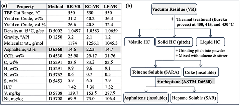
(a) VRs properties and (b) coke and asphaltene separation (HC: hydrocarbon; RB-VR: Ratawi-Burgan vacuum residue; LF-VR: Lower-Fars vacuum residue; EC-VR: Eocene vacuum residue).
2.2 Precipitation of asphaltene samples
The parent asphaltene samples in this study were extracted from the three VRs (i.e., before thermal cracking). The thermally-treated asphaltenes, on the other hand, are those samples extracted from the pitch. The coke formation is normally triggered by carbonization process and the phase separation from asphaltene (Avid et al., 2004; Wiehe, 1993). Fig. 1b indicates a difference between the coke and asphaltene where coke is insoluble in toluene while asphaltenes are soluble in toluene. Hence the pitch (about 5 g) sample was dissolved in toluene at 1:1000 (wt/wt) solid to toluene ratio, followed by 60 min mixing and then separated coke (0.5 to 1.5 g) as solid. At various thermal reaction conditions, the coke formation varies in the range of 10–35 wt%, which increases with increasing reaction temperature. Subsequently, toluene was distilled off from the filtrate (volume was reduced), and asphaltene samples were extracted according to the method described in the IP 143/90 (ASTM 6560) standard; n-heptane solvent extraction was used in a ratio of 30 ml to each 1 g of sample.
2.3 SEM/TEM characterization
The surface morphology of asphaltene was observed by SEM with EDS. SEM analyses were carried out on a JEOL JSM-IT300 with oxford instrumentation energy dispersive system. The samples were mounted on an aluminum sample holder with carbon adhesive tape and were sputter coated with gold. The conditions of analysis were of 20 to 30 kV. In all cases, the high vacuum was used, and the images were taken with the secondary electron detector. Elemental composition was studied by EDS using AZtecEnergy EDS software. The TEM microstructural analysis was performed on the asphaltene aggregates using a JEOL JEM-3010 transmission electron microscope with a 300-kV electron beam. Prior to analysis, asphaltene samples were ground in an agate mortar and ultrasonically dispersed in n-heptane. A drop of this solid/liquid dispersion was placed on a mesh carbon-coated Cu grid. TEM images were analyzed by using Digital - Micrograph 3.4 software, particularly line profile and line plot on the images for distance calculation (image statistics).
3 Results and discussion
The current study aims at evaluating the impact of thermal cracking on asphaltene morphology using SEM, EDS, and TEM. The morphological changes were monitored by comparing asphaltene extracted from AR, VR (parent asphaltene before cracking), and pitch samples (thermal cracking by-product), which were obtained at three cracking temperatures (400, 415, 430 °C). To validate the observed results, the study has been conducted on asphaltenes from different origins. The secondary asphaltene formation from resin and aromatic was reported by Favre and Boulet (1984), Favre et al. (1985). In their pyrolysis study, Favre and coworkers indicated that the maltene obtained from C7 separation formed asphaltene through resin and aromatic recombination while the maltene from C5 separation cannot form asphaltene through pyrolysis. However, the complexity of the asphaltene structure is extensive and not limited to the aromatic sheet stacking and requires the development of a typical polar nature. Furthermore, the operating conditions in residual oil thermal treatment favor the cracking reactions. Moreover, there is scarcity in the literature about secondary asphaltene formation during the thermal cracking of residual oils. The condensation reaction, on the other hand, is possible during the thermal cracking, but it mainly generates coke or poly-nuclear aromatic (PNA) compounds. Therefore, this study can neither confirm nor deny the secondary asphaltene formation from resin and aromatic, but such information needs to be proven experimentally and can be a subject for future investigation, but it is beyond the scope of this work.
3.1 SEM analysis
Asphaltene aggregates exhibited different changes in surface morphology during thermal cracking. The extent of change in morphology depends on the asphaltene type and origin, as well as the severity of the thermal cracking condition. Fig. 2 illustrates SEM images of asphaltene obtained from EC-AR, EC-VR, EC-VR 400 °C, EC-VR 415 °C, and EC-VR 430 °C. Fig. 2a indicates that the asphaltene aggregates from EC-AR have both smooth and rough surfaces on which agglomerated particles are deposited. These agglomerated particles are most likely attributed to the presence of resinous materials (or maltene fractions) that are normally attached to asphaltene to support their dispersion in oil. The surface also illustrates bright particles that correspond to inclusions, in which Si, O, Na, Mg, Cl, and S are abundant, as revealed by following EDS analysis. The higher magnification image in the supplementary data illustrates obvious marks on the surface morphology of asphaltene aggregates that are caused by the removal of inclusions. These bright inorganic inclusions have been reported in previous SEM studies (Camacho-Bragado et al., 2001; Perez-Hernandez et al., 2003; Arenas-Alatorre et al., 2016; Qin et al., 2019) and were mainly composed of O, Na, Mg, Si, Cl, and K.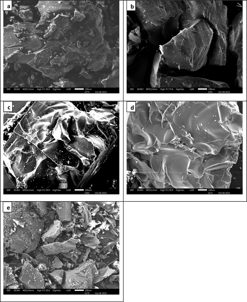
SEM images of asphaltenes (a) EC-AR: (b) EC-VR, (c) EC-VR 400 °C, (d) EC-VR 415 °C (e) EC-VR 430 °C.
The SEM images for asphaltene aggregates extracted from EC-VR is shown in Fig. 2b, which exemplifies two surface morphologies; smooth surfaces and rough surfaces with stretch marks (supplementry data, S1-S5). On both surfaces, the degree of agglomeration and the intensity of inclusions have decreased. The decrease in agglomeration and the appearance of stretch marks are indicators of resin detachment and removal. The stretch marks on the rough surfaces are very distinct with consistent and uniform space of around 10 µm. These stretch marks are very similar to the fatigue striations observed in metals and/or alloys, and they can be also attributed to the progressive fracturing of asphaltene aggregates. The comparison between asphaltene aggregates of EC-AR and EC-VR indicates a notable reduction in inclusion intensities and sizes (i.e., 10 μm).
The SEM images of asphaltene extracted from Eocene pitch after mild cracking (400 °C) are illustrated in Fig. 2c, which demonstrates undulated surfaces with small bright inclusions (S1-S5). Higher magnification images show fine stress lines on smooth surfaces. As the cracking severity increases (415 °C), the intensity of inclusions on the surface decreases, and smooth cleavage-like features start to be more evident (Fig. 2d). The increase in cracking severity also contributed to the formation of deep grooves, cleavage planes, and cleavage fractures, as shown in the higher magnification of the images. The formation of these patterns might likely be credited to the elimination of maltene that occupies the interstices or gaps in asphaltene particles. At the most severe cracking condition (i.e., 430 °C), the surface of asphaltene aggregates became more fragmented and shattered due to the further elimination of maltene and aliphatic fractions (Fig. 2e). The higher magnification images illustrate the cleavage facets, grooves, and the brittle fractures (or micro-cracks), which have also been observed at the 415 °C.
The impact of thermal cracking on asphaltenes extracted from RB, Fig. 3, revealed some similarities and differences compared to the ones from EC (Fig. 2). The microscopic examination of asphaltene aggregation of RB-AR in Fig. 3a shows a ridge-pattern surface with irregular shapes of bright inclusions that are rich in Si, O, Na, Mg, Cl, and S. The surfaces have randomly distributed cavities of 1–2 µm diameter. These cavities or pores can be associated with the removal of small molecules of adsorbed resin on asphaltene. The images also illustrates stress lines that are commonly observed on these surfaces. These stress lines, as well as the porous structure, can generally be ascribed to the elimination of maltene fractions (i.e., saturates, aromatics, and resins) from asphaltene aggregation.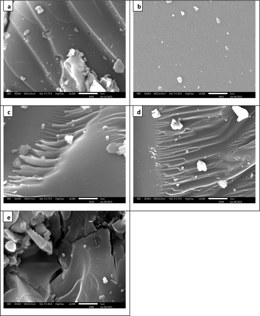
SEM images of asphaltenes (a) RB-AR: (b) RB-VR, (c) RB-VR 400 °C, (d) RB-VR 415 °C, (e) RB-VR 430 °C.
The microstructure of asphaltene aggregates extracted from RB-VR reveals significant changes when compared to the corresponding asphaltene from the atmospheric residue (RB-AR). First, the intensity and the sizes of inclusions obviously decreased, as shown in Fig. 3b, which is in agreement with the previous observation for asphaltenes extracted from EC-AR and EC-VR. Moreover, the cavities almost disappeared from this morphology (supplementary data, S6-S10) and were scarcely observed at very high magnification. The disappearance of cavities is difficult to explain, but it might be associated with the effect of vacuum distillation.
The morphology of asphaltene aggregates extracted from RB pitch after thermal cracking at 400 °C illustrates river-pattern surfaces with inclusions of different sizes (Fig. 3c). River-pattern is another form of cleavage planes, which presumably results from the elimination of maltene from asphaltene aggregates through thermal cracking. Cavities were also observed on these surfaces but only at high magnifications. The cavities observed with thermal cracking can be also attributed to the loss of volatile components during the thermal cracking of the liquid phase. The increase in thermal cracking temperature to 415 °C formed morphology similar to cleavage fracture as shown in Fig. 3d. Cleavage cracks were also apparent in this surface. As stated previously, both the cleavage facets and cracks are apparently caused by the additional removal of maltene with the increase in cracking temperature. The river-pattern morphology is still observed on these surfaces but only at high magnifications. Cavities, on the other hand, were not observed on these surfaces even at high magnifications. The further increase in thermal cracking severity (i.e., 430 °C) formed more brittle fractures and voids on the asphaltene aggregate morphology, as shown in the images of Fig. 3e. The morphology also exhibits an obvious reduction in inclusions and agglomerate particles. In addition, the cavities were not observed on these surfaces. The disappearance of cavities can be associated with the formation of microcracks.
The changes observed in asphaltene aggregations of LF are also addressed in Fig. 4. The asphaltene extracted from LF-AR has cleavage facets with agglomerated particles and inclusions as shown in Fig. 4a. The higher magnification images have stress lines and micropores of 0.25 µm diameter. Structures of cleavage planes (steps-like morphology) were frequently observed. The asphaltene aggregates of LF-VR exemplified some morphological changes when compared to the ones extracted from LF-AR. For example, the intensities of agglomerated particles and inclusions have slightly decreased as shown in Fig. 4b, where the removal of the inclusions left obvious marks on the surface. The surface also illustrated a river-pattern morphology with obvious stress lines. The cavities have disappeared from the surface even at high magnifications. Similar observations were previously noted in the case of EC and RB.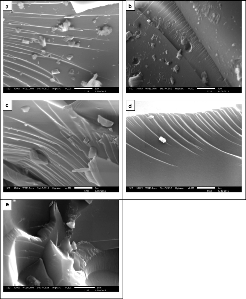
SEM images of asphaltenes (a) LF-AR: (b) LF-VR, (c) LF-VR 400 °C, (d) LF-VR 415 °C, (e) LF-VR 430 °C.
The impacts of mild thermal cracking on LF asphaltene aggregates are illustrated in Fig. 4c. The SEM images suggest significant reductions in the intensities of inclusions and other agglomerate particles, which resulted in cleavage fracture morphology. The fine stress lines, previously observed in LF-AR and LF-VR samples, became more evident in the thermally treated sample, as illustrated in higher magnification images, which also illustrates the river-patterns that are frequently observed in this surface, as a result of cleavage cracks (supplementary data, S11-S15). The increase in cracking temperature to 415 °C resulted in a further reduction in inclusion, deeper stress lines, cavities, and brittle cleavage fracture features, as shown in the images of Fig. 4d. With further increase in cracking severity (i.e., 430 °C), the cleavage fracture morphology started to become more obvious, as shown in Fig. 4e. Higher magnification images also illustrated brittle cleavage fractures (micro-cracks) and micro-pores.
The above observations from SEM analyses can be summarized as follows:
-
The asphaltene aggregates obtained from atmospheric residues (ARs) have amorphous surfaces with agglomerate particles and bright inclusions. The deposited agglomerate particles are related to resinous materials or maltene fractions, typically attached to asphaltene aggregates to support their suspension and dispersion in oil. The irregular shapes of bright inclusions, on the other hand, are particles rich in heteroatoms such as Si, O, Na, Mg, Cl, and S. The higher magnification images illustrate fine stress lines and randomly distributed cavities and micro-pores (0.2–2 µm in diameter), which mainly result from the removal of the adsorbed resinous molecules from asphaltene aggregates.
-
The asphaltene aggregates extracted from the vacuum residues (VRs) showed a reduction in agglomeration and an evident decrease in inclusion intensities, where the removal of inclusions resulted in obvious marks on the surface morphology. In addition, obvious stretch marks and river patterns are also observed in these surfaces. Cavities and pores, on the other hand, are hardly seen on these surfaces even at high magnifications.
-
The SEM images of asphaltene aggregates extracted from the pitch samples after mild cracking at 400 °C demonstrate cleavage fracture morphology with obvious reduction in inclusions sizes and intensities. Stress lines and few cavities are also observed at high magnification images.
-
The cavities observed after thermal cracking either attributed to the loss of volatile components or the coke-precursor microparticles released from the asphaltene surface during the solvent extraction.
-
The increase in cracking temperature to 415 °C further reduced the inclusion intensity and generated deeper stress lines, grooves, and micro-cracks, which are most likely credited to the elimination of maltene fractions from the interstices and gaps in asphaltene aggregates. Further increase in cracking severity (i.e., 430 °C) resulted in cleavage fracture morphologies with more brittle fractures.
3.2 EDS analysis
For further investigating the presence of bright inclusions on asphaltene morphology that was indicated by the SEM analysis, EDS analysis was performed on asphaltene aggregates extracted from RB-AR. The EDS results for high and low inclusion intensities are shown in Fig. 5(a-c). In agreement with previous studies (Wang and Anthony, 2003; Perez-Hernandez et al., 2003), the surface of high inclusion intensity (supplementary data, S16) indicated relatively lower carbon content, which was compensated by high oxygen content and notable higher concentrations of other elements such as Si, Na, and Cl, and Ca. Nitrogen (N), however, was not detected in the SEM-EDS, which might be either due to the scarceness of this element in the irradiated zone (examined area) or the deep location of N inside the sample. The results were inconsistent and do not really represent the elemental composition in the examined samples. Further analyses clearly indicate that the elemental analysis by SEM-EDS significantly depends on the examined sites, which suggests that the surfaces of asphaltenes are inhomogeneous and the SEM-EDS results with regards to elemental compositions are not absolutely quantitative; but only indicative. Therefore, more quantitative elemental analyses can be obtained using the CHNS elemental analyzer and inductively coupled plasma optical emission spectrometry (ICP-OES).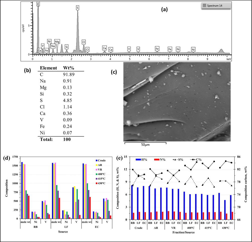
Molecular weight and compositional analysis (a) SEM-EDS spectrum, (b) EDS elemental results, (c) surface image (d) molecular weight and metal content (Ni &V), and (e) CHNS analysis.
In a previous study, Lababidi et al. (2014) monitored the changes in asphaltenes, similar to the ones used in this study during thermal cracking, and reported very important results that can implicitly complement the findings of this study. For example, they reported a significant drop in the average molecular weight of asphaltene as it is exposed to thermal cracking, while the successive atmospheric and vacuum distillations have limited impacts; Fig. 5d. Further studies on similar asphaltene molecules have indicated that the observed reductions in the molecular weights are mainly due to the breaking of alkyl side chains, while changes in the aromatic cores appear to be rather limited (AlHumaidan et al., 2015; 2016; 2017).
The elemental analysis data for asphaltenes before and after thermal cracking are shown in Fig. 5e. The elemental analysis results clearly indicate that the carbon content slightly increases with the increase in thermal cracking severity while hydrogen content decreases. The decrease in hydrogen content is more evident in LF asphaltenes because they are more prone to structural changes when compared to those from RB and EC, as suggested by AlHumaidan et al. (2015, 2016). In their XRD study (AlHumaidan et al., 2015), they reported a substantial decrease in the cluster diameter of LF asphaltenes after thermal cracking, which was attributed to the loss of aliphatic carbon in the side chains and the decrease in the number of aromatic sheets per stacks. The authors (AlHumaidan et al., 2016) also confirmed the vulnerability of LF asphaltenes toward thermal cracking. In contrast to hydrogen content, the change in nitrogen content is insignificant, which can be endorsed by the difficulty associated with nitrogen removal from the stable metal complexes within the asphaltene molecules. Similarly, the changes in sulfur content with thermal cracking are also insignificant, which might be related to the presence of sulfur in refractory thiophenic compounds (difficult to crack). In addition to the CHNS analysis, ICP-OES analysis provided a more quantitative analysis for Ni and V in asphaltene samples; Fig. 5d. The vanadium content is always greater than that of nickel, which is commonly observed in most crude oils. The general trend indicates that the contents of both metals reduce as the cracking severity increases. However, considering the difficulty of removing these metals from metal complexes (i.e., porphyrins) in the core of asphaltene, the reduction in metal content can be explained through the cracking of large asphaltene molecules into smaller molecules of a smaller amount of metals. This finding is in agreement with AlHumaidan et al. (2016), in which they described the asphaltene structure as an archipelago-type, where small aromatic cores are linked to each other by means of bridging alkanes. The thermal stress mainly removes the alkyl side chains from asphaltene molecules, which leaves the detached aromatic cores, where porphyrins are located, nearly intact. The low Ni and V contents in Fig. 5e explains the difficulty in locating them through the SEM-EDS analysis.
3.3 TEM analysis
In our previous XRD study (AlHumaidan et al., 2015), we gave an insight into the macrostructure of asphaltene by providing information about the dimensions of the crystalline parameters, which includes: the diameter of aromatic sheet plus α-carbons of alkyl chains (La), the average height of the stack of aromatic sheets perpendicular to the plane of sheet (Lc), interaromatic layer distance (dm), and the number of aromatic sheets associated in a stacked cluster (M) (Yen et al., 1961; Shirokoff et al., 1997; Qin et al., 2019). Further insight and verification of asphaltene macro-structure can be obtained through high-resolution TEM. A previous TEM study conducted by Perez-Hernandez et al. (2003) showed that purified asphaltenes are constituted by nanometric particles (micelles) with a diameter of approximately 50 nm. The agglomeration of these particles can reach diameters of 350 to 550 nm, some of them in layer arrangement with a propensity to graphitize. In agreement Perez-Hernandez et al. (2003), our TEM results showed that asphaltene mainly consists of irregular shape micelles of 50 to 100 nm in diameter and these micelles forms flocs of a diameter between 300 and 400 nm (supplementary data, S17).
Fig. 6a shows the TEM image of asphaltene precipitated from EC-AR. The image shows a tangled structure, which is mainly caused by the paraffinic chains located at the edges of the aromatic sheets of asphaltene molecules. These paraffinic or alkyl side-chains limit the stacking through steric interactions and consequently limit the growth of asphaltene aggregates. Fig. 6b, on the other hand, shows the TEM image of asphaltene extracted from EC-VR. Fig. 6b illustrates the tangled structure with edges like a cauliflower, with an average radius of around 2.5 nm. As previously stated, the observed tangled structure is mainly credited to the alkyl chains, which impede the aromatic sheets from stacking. The disordered and amorphous structures caused by the poor stacking of aromatic sheets are very evident near the edges and in the interior of the sample. Fig. 6c illustrates some asphaltene stack clusters with a layer distance between neighboring aromatic sheets of 0.36 nm, which is in agreement with our previous XRD study (AlHumaidan et al., 2015) where the layer distance between the aromatic sheets (dm) was reported to be 3.5 Å (0.35 nm). In order to define crystalline carbon-based molecular structure using XRD d002 spacing between 0.32 and 0.35 nm, which strongly depends on the perfect graphene structure (Jun, 2015; Kharissova and Kharisov, 2014). However, asphaltene is considered as a disorder layered structure that does not have continuous spacing, which is mainly due to the presence of hetero-atoms and alkyl side chains that are likely to influence the stacking spacing (d002). The TEM images reported in this study revealed a variation in the spacing from 0.33 nm to 0.39 nm with temperature, indicating changes (stacking of layers) due to the structural defects, which perfectly correspond to our XRD results (AlHumaidan et al., 2015). This is clear from the TEM results of the sp2 hybridized atomic orbit structure, which is a pie electron property. From the chemistry point of view, the thermal treatment of asphaltene leads to the structural changes that can be postulated in the form of cracking of side chain (mostly at the sheet edges), elimination of hetero-atoms, and cracking of aromatic sheet.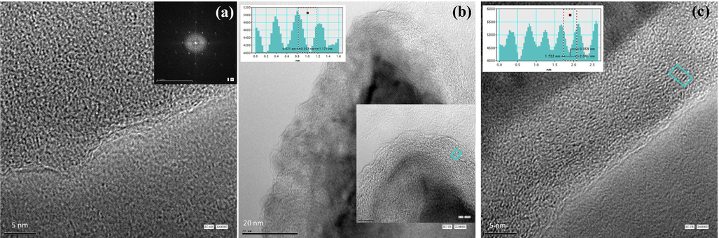
TEM image of asphaltene precipitated from (a) EC-AR, (b) EC-VR derived cauliflower edges with an average radius of 2.5 nm, and (c) EC-VR derived asphaltene stack clusters.
The impact of mild thermal cracking on asphaltene structure is illustrated in Fig. 7a for the asphaltene extracted from the Eocene pitch that is thermally treated at 400 °C. This sample exhibits a different arrangement when compared to the parent asphaltene from the VR. Near the edges, the asphaltene began to exhibit well-ordered layer structures, with fewer cauliflower edges. This stacked graphite-like structure near the edges is mainly caused by the rupture of the alkyl side chains, which allows the aromatic sheets to stack in the solid-state during precipitation. In the sample interior, however, the tangled structure was still preserved. The histogram in Fig. 7a indicates that the interlayer distance between the aromatic sheets remain unchanged at around 0.36 nm while the number of aromatic sheet per stack varies between 3 and 6. These finding are in agreement with our previous XRD results (AlHumaidan et al., 2015), where the average inter-aromatic layer distance was 0.36 nm, and the average number of aromatic sheet per stack was 4. The observed thermal cracking impact on asphaltene structure opposes the one reported by Trejo et al. (2009) for hydroprocessing, where the amorphous structures (poorly ordered structures) were preserved near the edges while the sample interior exhibited well-ordered layer structures with an interlayer distance between aromatic sheets of 0.36 nm. This observed variation between thermal treatment and hydrotreatment is mainly credited to the difference in reaction selectivity, where hydroprocessing is more selective and targets the heteroatoms in asphaltene core.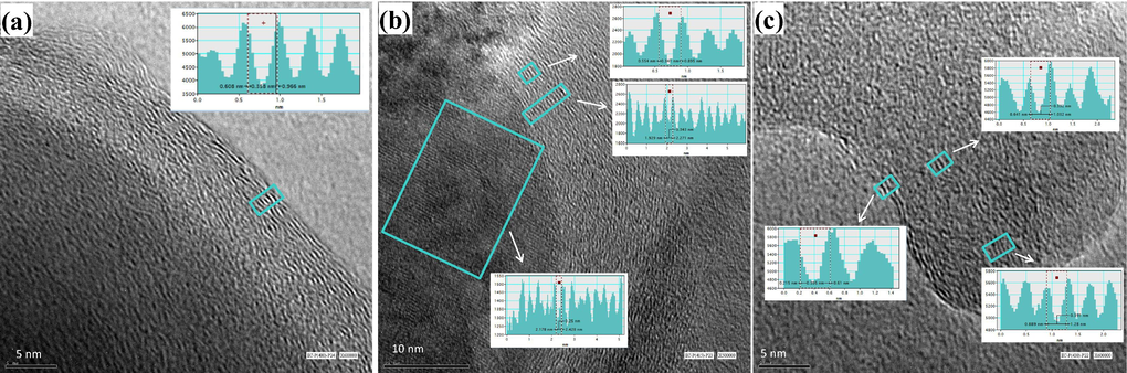
TEM image of asphaltene precipitated from EC pitch after thermal cracking of EC-VR at (a) 400 °C, (b) 415 °C, and (c) 430 °C.
As the thermal reaction severity increases, the stacking of aromatic sheets (i.e., well-ordered structure) started to become more evident even in the sample interior, as given in Fig. 7b. The interlayer distance between the aromatic sheets decreased, with the increase in cracking temperature, from 0.36 nm to approximately 0.34 nm. The average diameter of the aromatic sheet is around 1 nm (10 Å), which is close to the previously reported XRD results (i.e., La = 7.7 Å) (AlHumaidan et al., 2015). The increase in cracking temperature also revealed graphene lattice fringes of 0.250 nm layer distance, as shown in Fig. 7b. At 430 °C, an obvious reduction in the cluster diameter has been observed, which mainly resulted from the reduction in the number of aromatic sheet per stack (Fig. 7c). The decrease in aromatic sheet per stack was associated with an increase in the average inter-aromatic layer distance between the aromatic sheets, which becomes in the range of 0.39 nm. The observed changes in structural parameters for EC asphaltene are compatible with the ones previously reported by XRD (AlHumaidan et al., 2015).
The TEM image of asphaltene precipitated from LF-AR is shown in Fig. 8a. The image shows tangled structures and well-stacked structures, where the layer distance between aromatic sheets is around 0.36 nm. Fig. 8b, on the other hand, illustrates the structure observed in LF-VR, where a tangled structure with edges similar to cauliflower is observed. The tangled structures, caused by the poor stacking of aromatic sheets, are evident near the edges (i.e., cauliflower) and in the interior of the sample. The number of aromatic sheet per stack varies between 3 and 5, while the layer distance between the neighboring aromatic sheets remained unchanged at around 0.36 nm. These results are in agreement with our previous XRD findings (AlHumaidan et al., 2015), where the average number of aromatic sheet per stack was reported to be 3 and the distance between the aromatic sheets was 3.5 Å (0.35 nm).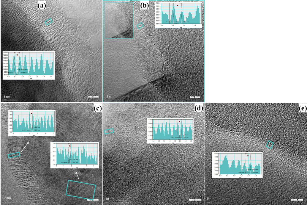
TEM image of asphaltene precipitated from (a) LF-AR, (b) LF-VR, (c) LF-VR treated at 400 °C, (d) LF-VR treated at 415 °C, and (e) LF-VR treated at 430 °C.
The impact of mild thermal cracking on LF asphaltene is shown in Fig. 8c, where the previously observed tangled structure near the edges began to disappear, and the aromatic sheet started to stack and form a well-ordered layer structure due to alkyl side-chains ruptures. The layer distance between the aromatic sheets slightly decreased from 0.36 nm to 0.34 nm, which is in agreement with the observation noted earlier for EC asphaltenes. The sample interior, on the other hand, exhibited graphene fringes of 0.25 nm. The increase in cracking temperature to 415 °C has not significantly affected the asphaltene structure as shown in Fig. 8d. However, a further increase in the temperature to 430 °C resulted in an obvious reduction in the number of aromatic sheet per stacks and an evident increase in the layer distance between the aromatic sheets (0.37 nm) as shown in Fig. 8e. This finding agrees with that of our previous findings (AlHumaidan et al., 2015; 2016; 2017; Lababidi et al., 2014), which indicated that LF asphaltene has the most notable decrease in molecular weight after thermal treatment, despite the fact that it has the highest molecular weight among the three parent asphaltene from the VRs. AlHumaidan et al. (2015), in their XRD study, also showed that the molecular structure of LF asphaltene is more affected by thermal cracking when compared to asphaltenes from RB and EC, where substantial decrease in the cluster diameter was observed due to the loss of aliphatic carbon in the alkyl side chains and the decrease in the number of aromatic sheet per stack. In a more recent study, Alhumaidan et al., (2016) evaluated the impact of thermal cracking on the different functional groups that exist in asphaltene molecules, where they indicated that LF asphaltene is more susceptible to thermal cracking when compared to RB and EC asphaltene. The lower stability and the vulnerability of LF asphaltenes toward thermal cracking were attributed to both the type and the size of the asphaltene molecules. It is believed that the asphaltene has an archipelago-type structure, which is represented by small aromatic cores (less than seven aromatic rings) linked to each other by alkyl bridges. Authors (AlHumaidan et al., 2016) believed that the relatively larger size of LF asphaltene and its higher heteroatoms content contributed to its instability in thermal cracking where the alkyl and the sulfur bonds that link the island of aromatic cores tend to crack under thermal stress easily.
The TEM image of asphaltene from RB-AR is shown in Fig. 9a, where a tangled structure is observed with edges similar to cauliflower with an average radius of 5 nm. The disordered structures and the poor stacking of aromatic sheets are observed all over the sample. Few stacking clusters are observed near the edges with a layer distance between the neighboring aromatic sheets of around 0.36 nm. Asphaltenes from RB-VR also illustrate the tangled structures but with a slightly better stacking of aromatic sheets near the edges (Fig. 9b). The distance between neighboring aromatic sheets decreases to around 0.35 nm, which is in agreement with the XRD measurement (AlHumaidan et al., 2015). The exposure of the sample to mild thermal cracking at 400 °C resulted in a slightly better stacking of aromatic sheets near the edges and in the sample interior (Fig. 9e). The distance between neighboring aromatic sheets slightly increased after mild thermal cracking from 0.35 nm to 0.36 nm, which is identical to the results obtained from XRD analysis (AlHumaidan et al., 2015). With the increase in cracking temperature to 415 °C, the sample interior illustrated better stacking of aromatic sheets while the distance between the aromatic sheets remained unchanged (i.e., 0.36 nm), as illustrated in Fig. 9d. The increase in cracking temperature from 415 to 430 °C resulted in a similar structure, and the distance between the aromatic sheets also remained unchanged at around 0.36 nm, as shown in Fig. 9e. The relatively limited structural changes in RB asphaltene with thermal cracking confirms the refractory nature of this asphaltene, which has been also confirmed in our previous studies (AlHumaidan et al., 2015; 2016).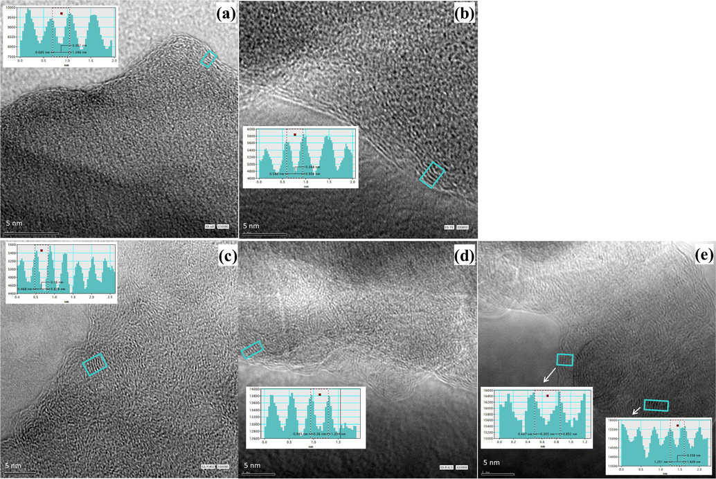
TEM image of asphaltene precipitated from (a) RB-AR, (b) RB-VR (c) RB-VR treated at 400 °C, (d) RB-VR treated at 415 °C, and (e) RB-VR treated at 430 °C.
4 Conclusions
The SEM images of asphaltene aggregates that are extracted from the pitch samples after mild cracking at 400 °C demonstrate cleavage fracture morphology with an obvious reduction in inclusions sizes and intensities. Stress lines and cavities observed at high magnification images are attributed to the loss of volatile components during the thermal cracking, which are released from asphaltene surface during the solvent extraction. The increase in cracking temperature to 415 °C further reduced the inclusion intensity and generated deeper stress lines, grooves, and micro-cracks, which are most likely credited to the elimination of maltene fractions from the interstices and gaps in asphaltene aggregates. Further increase in cracking severity (i.e., 430 °C) resulted in cleavage fracture morphologies with more brittle fractures.
The TEM analysis, on the other hand, indicated that the asphaltenes from residual oils have tangled structures, with edges similar to a cauliflower. This tangled structure is mainly credited to the alkyl side-chains that impede the aromatic sheets from stacking. The layer distance between neighboring aromatic sheets in the asphaltene stack clusters was around 0.36 nm. At mild cracking (400 °C), the asphaltene started to exhibit well-ordered layer structures near the edges due to the rupture of the alkyl side-chains. The define layers identified via TEM indicated that asphaltene is a layered material, which has similar structure to graphene hydrocarbon material. The interlayer distance between the aromatic sheets remain unchanged (around 0.36 nm) but the number of aromatic sheet per stack increased. As the reaction severity increases (415 °C), the stacking of aromatic sheets started to become more evident even in the sample interior. The increase in cracking temperature also revealed graphene lattice fringes of 0.250 nm layer distance. At the most severe cracking (430 °C), an obvious reduction in the cluster diameter was observed, which mainly resulted from the reduction in the number of aromatic sheet per stack. The decrease in aromatic sheet per stack was associated with an increase in the average inter-aromatic layer distance between the aromatic sheets.
Acknowledgments
The authors acknowledge the help taken from Prof. Abdulmajeed Safar, the director of electron microscopy, Kuwait University, and Mr. Mohammad Rajab for their support in conducting the TEM analysis.
Declaration of Competing Interest
The authors declare that they have no known competing financial interests or personal relationships that could have appeared to influence the work reported in this paper.
References
- Thermal cracking kinetics of Kuwaiti vacuum residues in Eureka process. Fuel. 2013;103:923-931.
- [Google Scholar]
- Changes in asphaltene structure during thermal cracking of residual oils: XRD study. Fuel. 2015;150:558-564.
- [Google Scholar]
- Impact of thermal treatment on asphaltene functional groups. Energy Fuels. 2016;30(4):2892-2903.
- [Google Scholar]
- NMR characterization of asphaltene derived from residual oils and their thermal decomposition. Energy Fuels. 2017;31(4):3812-3820.
- [Google Scholar]
- Studies on thermal cracking behavior of vacuum residues in Eureka process. Fuel. 2013;109:635-646.
- [Google Scholar]
- Asphaltene characterization as function of time on-stream during hydroprocessing of Maya crude. Catal. Today. 2005;109:162-166.
- [Google Scholar]
- Effects of catalyst properties on asphaltenes composition during hydrotreating of heavy oils. Pet. Sci. Technol.. 2004;22(1–2):219-225.
- [Google Scholar]
- Changes in asphaltene properties during hydrotreating of heavy crudes. Energy Fuels. 2003;17(5):1233-1238.
- [Google Scholar]
- Extraction and characterization of asphaltenes from different crude oils and solvent. Energy Fuels. 2002;16(5):1121-1127.
- [Google Scholar]
- Asphaltenes Chemical Transformation During Hydroprocessing of Heavy Oils. CRC Press - Taylor & Francis Group; 2009. p. :441.
- Electron microscopy characterization of crystalline nanostructures present in asphaltene. Energy Fuels. 2016;30(5):3752-3757.
- [Google Scholar]
- Characterization of asphaltenes from Brazilian vacuum residue using heptane-toluene mixtures. Energy Fuels. 2004;18:1792-1797.
- [Google Scholar]
- Changes in asphaltene stability during hydrotreating. Energy Fuels. 2000;14(1):52-55.
- [Google Scholar]
- Effect of hydrotreatment on product sludge stability. Energy Fuels. 2001;15(5):1059-1062.
- [Google Scholar]
- Molecular size of asphaltene fractions obtained from residuum hydrotreatment. Fuel. 2003;82(9):1075-1084.
- [Google Scholar]
- Preliminary studies of aspahltene aggregates by low vacuum scanning electron microscopy. Pet. Sci. Technol.. 2001;19(1–2):45-53.
- [Google Scholar]
- Structural study of asphaltenes from iranian heavy crude oil. Oil & Gas Sci. Technol. – Rev. IFP Energies Nouvelles. 2015;70(6):1035-1049.
- [Google Scholar]
- Etude par simulation en laboratoire de l'opération de viscoréduction. Oil & Gas Sci. and Tech. - Rev. IFP. 1985;40(5):609-623.
- [Google Scholar]
- Modifications structurales des residus lors du procede de viscoreduction. Oil & Gas Sci. Technol. - Rev IFP. 1984;39(4):485-496.
- [Google Scholar]
- Studies on the evolution of asphaltene structure during hydroconversion of petroleum residues. Catal. Today. 2008;130:429-438.
- [Google Scholar]
- Effect of asphaltenes on hydroprocessing of heavy oils and residua. Appl. Catal. A. 2005;295:89-94.
- [Google Scholar]
- NMR investigations on products from thermal decomposition of Kuwaiti vacuum residues. Fuel. 2013;113:506-515.
- [Google Scholar]
- Study on thermal cracking of Kuwait heavy oil (vacuum residue) and its SARA fractions by NMR spectroscopy. Energy Fuels. 2014;28:4321-4332.
- [Google Scholar]
- Jun, S.C., 2015. Fundamental of graphene, in: bin Mohd Yusof, A.R. (Ed.), Graphene-Based Energy Devices. Wiley-VCH Verlag GmbH & Co. KGaA, pp. 1–48.
- Variations of interlayer spacing in carbon nanotubes. RSC Adv.. 2014;4(58):30807-30815.
- [Google Scholar]
- Deactivation of a hydrotreating catalyst during hydroprocessing of synthetic crude by metal bearing compounds. Fuel. 2019;243:579-589.
- [Google Scholar]
- Changes in asphaltenes during thermal cracking of residual oils. Fuel. 2014;117:59-67.
- [Google Scholar]
- Characterization of asphaltenes precipitated with three light alkanes under different experimental conditions. Fluid Phase Equilib.. 2010;291(2):103-110.
- [Google Scholar]
- Effect of asphaltene contained in feed on deactivation of maya crude hydrotreating catalyst. Pet. Sci. Technol.. 2007;25(1–2):241-249.
- [Google Scholar]
- Thermal cracking of coal residues: Kinetics of asphaltene decomposition. Fuel. 1997;76(9):871-877.
- [Google Scholar]
- Effects of asphaltene aggregation in model heptane-toluene mixtures on stability of water-in-oil emulsions. J. Colloid Interface Sci.. 1997;196(1):23-34.
- [Google Scholar]
- Evaluation of asphaltene structure during hydroconversion conditions. Energy Fuels. 2006;20(5):2028-2036.
- [Google Scholar]
- Size exclusion chromatography: characterization of heavy petroleum residues,application to resid desulfurization process. Petrol. Sci. Technol.. 2004;22(7–8):1003-1022.
- [Google Scholar]
- Microstructural study of asphaltene precipitated with methylene chloride and n-hexane. Fuel. 2003;82(8):977-982.
- [Google Scholar]
- From coal-heavy oil co-refining residue to asphaltene-based functional carbon materials. ACS Sustainable Chem. Eng.. 2019;7(4):4523-4531.
- [Google Scholar]
- Dependence of molecular kinetics of asphaltene cracking on chemical composition. Pet. Sci. Technol.. 2007;25(1–2):141-152.
- [Google Scholar]
- Liquid-phase behavior during the cracking of asphaltenes. Ind. Eng. Chem. Res.. 2003;42:4101-4108.
- [Google Scholar]
- Rana, M.S., Ancheyta, J., Maity, S.K., Rayo, P., 2007a. Hydrotreating of Maya crude oil: I. Effect of support composition and its pore-diameter on asphaltene conversion. Petrol. Sci. Technol. 25, (1–2), 187–199.
- A review of recent advances on process technologies for upgrading of heavy oils and residua. Fuel. 2007;86(9):1216-1231.
- [Google Scholar]
- Asphaltene aggregation from vacuum residue and its content of inorganic particles. Pet. Sci. Technol.. 2006;24(9):1055-1066.
- [Google Scholar]
- Structural changes of petroleum asphaltenes and resins by hydrodemetallization. Energy Fuels. 2000;14(5):980-985.
- [Google Scholar]
- Probing order in asphaltenes and aromatic ring systems by HRTEM. Energy Fuels. 2002;16(2):490-496.
- [Google Scholar]
- Characterization of the structure of Saudi crude asphaltenes by X-ray diffraction. Energy Fuels. 1997;11:561-565.
- [Google Scholar]
- Renewed attention to the eureka process: Thermal cracking process and related technologies for residual oil upgrading. Stud. Surf. Sci. Catal.. 1996;100:293-301.
- [Google Scholar]
- Characterization of asphaltene aggregates using X-ray diffraction and small-angle X-ray scattering. Energy Fuels. 2004;18(4):1118-1125.
- [Google Scholar]
- Characterization of asphaltenes from hydrotreated products by SEC, LDMS, MALDI, NMR, and XRD. Energy Fuels. 2007;21(4):2121-2128.
- [Google Scholar]
- Kinetics of asphaltenes conversion during hydrotreating of Maya crude. Catal. Today. 2005;109:99-103.
- [Google Scholar]
- Effect of hydrotreating conditions on Maya asphaltenes composition and structural parameters. Catal. Today. 2005;109:178-184.
- [Google Scholar]
- Structural characterization of asphaltenes obtained from hydroprocessed crude oils by SEM and TEM. Energy Fuels. 2009;23(1):429-439.
- [Google Scholar]
- A phase-separation kinetic model for coke formation. Ind. Eng. Chem. Res.. 1993;32:2447-2454.
- [Google Scholar]
- A study of thermal-cracking behavior of asphaltenes. Chem. Eng. Sci.. 2003;58(1):157-162.
- [Google Scholar]
- Investigation of the structure of petroleum asphaltenes by X-ray diffraction. Anal. Chem.. 1961;33:1587.
- [Google Scholar]
- Asphaltenes: Separations, structural analysis and applications. J. Energy Chem.. 2019;34:186-207.
- [Google Scholar]
Appendix A
Supplementary material
Supplementary data to this article can be found online at https://doi.org/10.1016/j.arabjc.2020.03.016.
Appendix A
Supplementary material
The following are the Supplementary data to this article:Supplementary Data 1
Supplementary Data 1


