

Translate this page into:
Copper doped manganese dioxide as counter electrode for dye-sensitized solar cells
⁎Corresponding author. bhaljafari@nu.edu.sa (Belqasem Aljafari),
-
Received: ,
Accepted: ,
This article was originally published by Elsevier and was migrated to Scientific Scholar after the change of Publisher.
Abstract
Abstract
Synthesize α-MnO2 and Cu doped MnO2 nanoparticles by hydrothermal method. Cu doped MnO2 is utilized as counter electrode candidate for dye-sensitized solar cells. 10 wt% Cu doped MnO2 as CE showed the best VOC (941 mV) and ISC (3.8 mA/cm2)
Abstract
Many materials have been tried as the counter electrode (CE) material as a substitute to the noble metal Pt in dye-sensitized solar cells (DSSCs). The CE property is critical to the operation of a DSSC as it catalyzes the reduction of I3- ions and retrieves the electrons from the photoanode. Here we have explored the application of manganese dioxide (MnO2) and copper-doped manganese dioxide (Cu-MnO2) nanoparticles as CE candidates for DSSCs mainly as low-cost alternatives to Pt. A simple hydrothermal method was followed to synthesize α-MnO2 and Cu-MnO2 nanoparticles at a temperature of 140 °C for 14 h. The nanoparticles were characterized to prove its electrocatalytic abilities for DSSCs. DSSC devices fabricated with 10 wt% Cu-MnO2 as CE showed the best VOC of 781 mV, ISC of 3.69 mA/cm2, FF of 0.50, and %PCE of 1.7 whereas Pt as CE showed VOC of 780 mV, ISC of 14.8 mA/cm2, FF of 0.43, and %PCE of 5.83 under 0.85 Sun. The low-cost feature of using Cu-MnO2 is encouraging to further study the factors that can improve the efficiency of DSSCs with alternative CEs to conventional Pt electrodes.
Keywords
Cu doped MnO2
Counter electrode
DSSC
Efficiency
IPCE

1 Introduction
Photovoltaic is truly a sustainable and environmentally friendly method of producing energy [Kiran et al., 2016; Zulkifli et al., 2015]. Dye-sensitized solar cells (DSSCs) are alternatives to silicon solar cells with the advantages of higher efficiency in diffused light, better cost-effectiveness, and easy fabrication [Chiba et al., 2006]. DSSC has four major parts: photoanode, sensitizer, redox electrolyte, and photocathode. The typical choice of photocathode or counter electrode (CE) material is platinum (Pt) due to its high catalytic activity and excellent stability toward the iodide redox species [Kim et al., 2006]. Since it is a costly noble metal and retreating supply, other materials have been under search to substitute Pt [Thomas et al., 2014]. Conducting polymers, carbonaceous materials, and transition metal compounds are some of the alternative materials introduced for the fabrication of DSSCs [Thomas et al., 2014].
It should have an energy level that matches the electrolyte potential and possess enhanced electrocatalytic activity, good reflectivity, and high surface area. Besides transparency, good reflectivity of CE is needed for illumination on the photoanode side. The electrochemically active surface of the CE should also preferentially be porous, have an optimum thickness, have chemical and electrochemical stability, be resistant to corrosion, have good adhesivity with the substrate, be low-cost, and be environmentally friendly. Atli and Yildiz (2022) reported a power conversion efficiency of 5.06% even with opaque Pt film assigned as a CE compared to transparent Pt CE (4.31%). This is because the high coverage (homogeneity) occurs in the case of transparent Pt CE due to the smaller particle size leading to an increase in the possibility of light interactions and reflections. [Atli and Yildiz, 2021; Atilgan and Yildiz, 2022].
Noticed, wide studies have been reported towards conducting polymers (poly(3,4-propylenedioxythiophene), polypyrrole (PPy), porous poly(3,4-propylenedioxythiophene), polythiophene (PTs), etc.,) as cathodes in DSSCs due to their good conductivity, and environmental stability [Jeon et al., 2011; Huang et al., 2012; Kim et al., 2011]. Likewise, carbon families (activated carbon, carbon nanotubes, and graphene) show exceptional catalytic activity towards the redox species upon being used as CEs in DSSCs [Murakami et al., 2008; Nam et al., 2010].
Transition metal carbides (MoC, VC, WC, NbC, TiC, Cr3C2, and Ta4C3) may act as smart CE materials because of superior catalytic activity, high electrical conductivity, and good thermal stability properties [Wu et al., 2012; Yun et al., 2013; Paranthaman et al., 2016]. Cai et al., 2017 fabricated DSSCs using copper-doped iron carbide (0.75%) as CEs resulting in the highest energy conversion efficiency of 5.68%. Such efficiency may be due to the excellent conductive properties of uniformly dispersed copper over iron carbide, which facilitates high electron transfer. Noble metal-like behavior of transition metal nitrides (TiN, MoN, WN, VN, NbN, CrN, NiN, Mo2N, W2N, Fe2N, and Ta4N5) due to the electronic structure similarity renders them as CE materials in DSSCs [Furimsky 2003; Kang et al., 2015; Zhang et al., 2012; Jiang et al., 2009]. Also, metal chalcogenides of various compositions were introduced as CEs show enhanced photovoltaic performance than ubiquitous platinized cathodes [Olsen et al., 2000]. Wu et al. fabricated DSSCs with MoS2 and WS2 as CEs that results in photoconversion efficiency of 7.59 % and 7.73 %, respectively [Wu et al., 2011]. Yildiz et al. reported Iron Phosphide (FeP) as CEs generates an efficiency of 3.96% which is comparate to the Pt CE. Besides, DSSCs are fabricated with transition metal oxides such as WO2 and NbO2 as CE generates photoconversion efficiency of 7.25% and 7.88% found close to DSSC with Pt CE (7.57%) [Zhou et al., 2013; Lin et al., 2011]. Ahmad et al., 2017 have synthesized α-MnO2 nanorods by facile hydrothermal method and utilized them as CE in DSSCs resulting in an open-circuit voltage of 0.75 V and fill factor (0.38). Likewise, MnO2-coated carbon nanofiber was used as CE which resulted in higher open-circuit voltage (0.78 V), fill factor (0.68), and PCE (8.86%). In continuation, various researchers coupled MnO2 with NiO and TiO2 layer-by-layer architecture and utilized them as CEs for DSSCs which shows higher efficiency compared to the pristine MnO2 layer [Kakroo et al. 2020, Datta et al. 2020]. Copper having excellent conductive properties upon doped on MnO2 results in enhanced electrochemical behaviour [Li et al., 2013; Ding 2010; Davis et al., 2014; Gao et al., 2018; Julien et al., 2017; Wei et al., 2011; Kakroo et al., 2020]. Considering the various choices of materials, the search for finding a low-resistance and low-cost alternative to Pt still needs more research [Thomas et al., 2014]. The promising results from doped metal oxides have motivated us to further study MnO2 and Cu doped MnO2 as CEs in DSSCs, particularly focusing on the effect of doping level on the performance of the MnO2 electrode as a CE for DSSCs. This is because the transition metal oxide MnO2 has certain advantages such as low-cost, high natural abundance, high theoretical capacity (1370 Fg−1), high voltage window, etc. Since its capacitance and conductivity are low, cationic doping has been proved to be effective to improve the conductivity and of which copper cations are found to improve electrochemical performance far better compared to other cations [An et al. 2019]. Further, the conductivity is based on electron concentration and mobility of electrons and hence we preferred to choose low dopant ratios (1, 5, 10 %wt). Hence in this study, MnO2 and copper doped MnO2 nanoparticles were prepared by hydrothermal approach and investigated as CEs in DSSCs.
2 Experimental methods
135 ml deionized water (DI) was added to potassium permanganate (KMnO4) (1185.25 mg) slowly as the solution was stirred until it was dissolved completely. Then, different weight percentages (1, 5, 10 %) of copper acetate were added until it was fully dissolved. Afterward, the mixture was acidified by adding 2.5 ml of HCl. The whole mixture was transferred to a Teflon-lined autoclave and kept at 140 °C for 14 h. Finally, the product (Cu doped MnO2) was regenerated by washing with DI water, and ethanol and dried at 80 °C for 24 hrs. A similar procedure was followed in the absence of copper acetate to generate pristine MnO2 [Luo et al., 2008].
Refer to supporting information regarding a list of equipment used to characterize the prepared nanomaterials and for the experimental procedure followed towards the fabrication of solar cell devices.
3 Results and discussions
As shown in Fig. 1(A), the XRD pattern of the synthesized pristine MnO2 and 1, 5, & 10 wt% copper doped MnO2 nanoparticles by the hydrothermal method exhibited a well-defined diffraction pattern which is in good harmony with the testified crystalline α-MnO2 (JCPDS data card no. 44–0141). [Ahmad et al., 2017; Yang et al., 2019] The diffraction peaks of both the samples appear at (12.6°), (18.03°), (28.5°), (37.4°), (41.5°), (49.8°), (55.9°), (59.8°), and (65.3°), are corresponding to the (1 1 0), (2 0 0), (3 1 0), (2 1 1), (3 0 1), (4 1 1), (6 0 0), (5 2 1), and (0 0 2) planes of α-MnO2 respectively [Ahmad et al., 2017]. XRD patterns of Cu doped MnO2 samples were also studied and results without any alterations in peaks belonging to α-MnO2 were observed. Since the copper species are highly homogeneous and well dispersed; hence no characteristic peak of Cu or CuO has been seen even for the 10 wt% Cu doped MnO2 sample [Yang et al., 2019]. The calculated crystallite size (using Scherrer formula) of 10 wt% Cu doped MnO2 is found smaller (23 nm) compared to the pristine MnO2 sample (27 nm).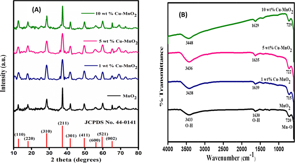
(A) XRD patterns and (B) FTIR spectra of MnO2 and 1, 5, & 10 wt% Cu doped MnO2 nanoparticles.
Similar to XRD, both MnO2 and 1, 5, & 10 wt% Cu doped MnO2 show the same IR stretching peaks upon the analysis in the Fourier Transform-Infrared (FTIR) spectrometer (Fig. 1(B)). The stretching and bending vibrations of the hydroxyl groups and the hydrogen-bonded surface water molecules are found at 3438 cm−1 and 1629 cm−1 [Yang et al., 2019; Mondal et al., 2018; Mondal et al., 2019] The Mn-O vibration band is seen near 700 cm−1 which further supports the formation of MnO2. Such observed results are due to two factors: (i) the amount of doping is a trace (even increased to 10%) and (ii) due to the same crystal size Cu doping can substitute manganese ions (results peak broadening). [Mondal et al., 2018].
To determine the optical energy bandgap of MnO2 and Cu doped MnO2 nanoparticles, the UV–Vis absorption spectrum was recorded. All the samples show a broad absorption band starting from 800 nm onwards which can be recognized due to d-d transitions of manganese ions (Figure not provided). The photoexcited electron from the valence band to the conduction band takes place due to Mn 3d energy level splitting [Mondal et al., 2018; Mondal et al., 2019]. Converting the photoabsorption data to the Tauc plots in Fig. 2, the optical energy bandgap (Eg) was predicted indirectly from the plots by using the following formula:
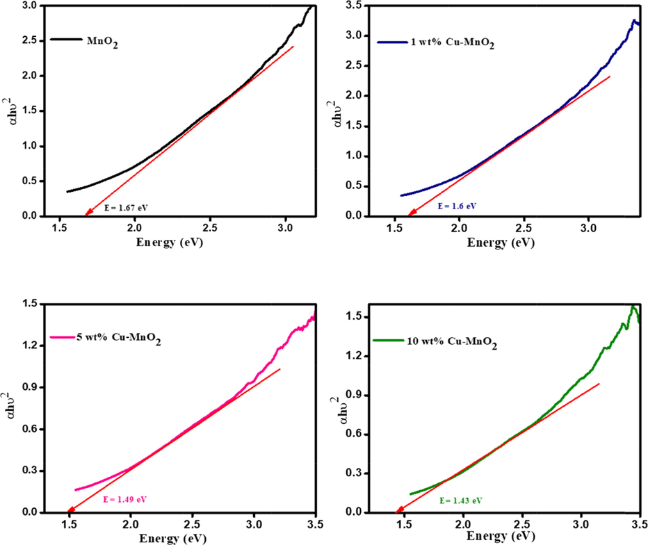
Tauc plot of MnO2 and 1, 5, & 10 wt% Cu doped MnO2 nanoparticles.
Pristine MnO2 shows a bandgap value of about 1.67 eV and upon doping with copper (1, 5, 10 wt%) noticed bandgap get lowers to 1.6, 1.49, and 1.43 eV which clearly illustrates that light absorption got enhanced with Cu dopant (Fig. 2). In addition, such copper dopants may suppress the recombination rates at the electrode/electrolyte/dye interfaces [Atilgan and Yildiz, 2022].
Both pure MnO2 and Cu doped MnO2 looked semispherical with coarse surface morphology under FE-SEM analysis (Fig. 3 a-d). Compared with pristine MnO2, Cu doped MnO2 has a slight difference in morphology and not noticed any lump which proved no agglomeration of particles. Such a larger particle size increases the scattering of light and thus allows the way light travels inside the device [Atli and Yildiz, 2022; Atilgan and Yildiz, 2022]. Besides it favors the penetration of the electrolyte and hence occurs quick electron transfer between the mediators (iodide/triiodide) in the electrolyte and the CE [Yang et al., 2019; Vijayakumar et al., 2015]. The EDX elemental analysis confirms the existence of individual metals only in the prepared pure MnO2 (Mn-67.21; O-32.78) and 10 wt% Cu doped MnO2 (Cu-9.12; Mn-55.22; O-35.66) samples (Fig. 3 e,f). It is found that the observed EDX results are almost matching with the 10 wt% Copper dopant amount taken for the experiment. In TEM analysis (Fig. 3 g,h,j,k), also, samples show similar spherical morphology as seen in the SEM images. The selected area electron diffraction patterns also illustrate the samples were well crystallized in nature. (Fig. 3 i,l).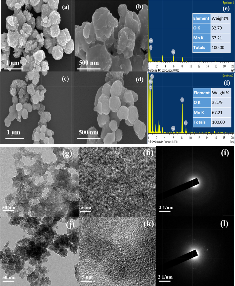
FE-SEM micrographs of (a-b) MnO2, (c-d) 10 wt% Cu- MnO2 and (e,f) EDS images of MnO2 and 10 wt% Cu- MnO2 nanoparticles. TEM micrographs of (g,h) MnO2, (j,k) 10 wt% Cu- MnO2 and (i,l) SAED images of MnO2 and 10 wt% Cu- MnO2 nanoparticles.
The cyclic voltammograms (CVs) of MnO2 and copper doped MnO2 thin layer electrodes (Fig. 4) look sigmoidal and symmetrical in shape due to the slow ion transport that may stimulate the fabricated DSSCs towards the effect of sunlight and as well as avoid back electron transfer. As can be observed from CV loops, the device having the Pt shows the highest IPC and EPP value (4.80 mAcm−2 and 1000 mV) which indirectly indicates the good electrocatalytic activity of Pt CEs toward the liquid electrolyte [Yildiz et. al. 2021]. Again, the higher IPC of Pt suggests a better electrocatalytic activity which may be reflected in the device’s performance. No certain oxidation and reduction peaks for Cu doped MnO2 samples, hence it is not possible to determine IPC and EPP values. Since the prepared Pt-coated electrode showed a symmetric response with the two distinct peaks due to fast electron transfer from the counter electrode to the electrolyte (reduction of iodine/iodide electrolyte: I3- + 2e- → 3I-) [Vijaya et al., 2021].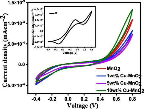
CV curves of MnO2 and 1, 5, & 10 wt% Cu doped MnO2 Nanoparticles. (Inset shows CV for Pt electrode for comparison).
Cu doped MnO2 coated FTO glass plates were sandwiched one above the other for symmetrical dummy cell fabrication towards electrochemical impedance spectroscopy (EIS) measurements. Parafilm was used to avoid contact with each other. The electrolyte (an iodide/triiodide (I-/I3-) solution) consisting of LiI/I2 (0.05 M/0.01 M), and LiClO4 (0.5 M) dissolved in 3-methoxy-propionitrile was injected in between the two glass plates. The electrochemical impedance spectroscopy (EIS) studies for such thin layer symmetrical electrodes were carried out under the following experimental conditions (frequency − 0.1 to 105 Hz; AC voltage − 10 mV). The Nyquist plot (Fig. 5) is projected against real impedance (Z') vs imaginary impedance (-Z“) gives information about the resistance data at TiO2/dye/electrolyte and electrolyte/CE. Also included equivalent circuit model in the inset of Fig. 5. The electron-hole charge transfer, diffusion of ions, and electron recombination at the TiO2/dye/electrolyte interface are related to resistance. The series/bulk resistance (RS) represents the FTO plates resistance along with the resistance of the counter electrodes can be investigated from the origin of the semicircle (the high-frequency region). The diameter of the semicircle of the mid-frequency region represents the charge transfer resistance (RCT) indicates the I-/I3- reduction catalytic activity [Wu et. al. 2017]. The response at low frequency region is attributed to Warburg resistance, Zw of I3-, tri-iodide diffusion [Wang et al. (2015)]. Further, the EIS parameters extracted from the Nyquist plot (Fig. 5) are listed in Table 1. From this table, the RS values of the respective CEs follow the order: 1 wt% Cu- MnO2 CE (38.62 Ω cm2) > 10 wt% Cu- MnO2 CE (35.55 Ω cm2) > Pt CE (31.97 Ω cm2) > MnO2 CE (30.29 Ω cm2) > 5 wt% Cu- MnO2 CE (29.87 Ω cm2). The RS values of the Pt (31.97 Ω cm−2) is less than 10 wt% Cu doped MnO2 (35.55 Ω cm−2) confirming the superior electrical conductivity of the Pt electrode. Further, the 1 wt% Cu doped MnO2 shows the lowest RCT value of 157.95 Ω cm−2 compared to Pt (191.53 Ω cm−2) and 10 wt% Cu doped MnO2 (204.9 Ω cm−2). The better electrocatalytic activity of Cu doped MnO2 toward the liquid iodide/triiodide electrolyte is confirmed by these EIS results.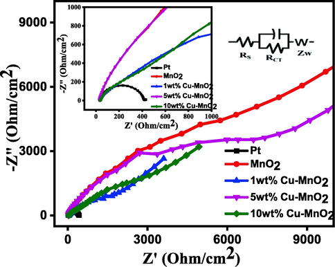
Nyquist plots of symmetrical dummy cells fabricated with Pt, MnO2, 1 wt% Cu-MnO2, 5 wt% Cu-MnO2, and 10 wt% Cu-MnO2 CEs. Inset see equivalent circuit of CEs.
Electrodes
RS (Ω cm2)
RCT (Ω cm2)
J0 (mA cm−2)
Pt
31.97
191.53
1.17
MnO2
30.29
164.70
0.0089
1 wt% Cu- MnO2
38.62
157.95
0.0079
5 wt% Cu- MnO2
29.87
278.46
0.0067
10 wt% Cu- MnO2
35.55
204.90
0.0055
Also, Bode phase plots for thin layer electrodes were measured to calculate the electron lifetimes (Fig. 6) from the equation.
where τ - electron lifetime and f - frequency [Sarker et al., 2014]. The calculated electron lifetime for Pt, MnO2, 1 wt% Cu-MnO2, 5 wt% Cu-MnO2, and 10 wt% Cu-MnO2 CEs dummy cells are found to be 99, 32, 43, 57, and 75 ms. The peak noticed in the high-frequency region is correlated to the charge transfer that occurs at the electrode/electrolyte interfaces [Kim et al., 2012]. Copper-doped MnO2 samples are found to have a phase shift lower than undoped samples indicating lower resistance for pristine MnO2 samples.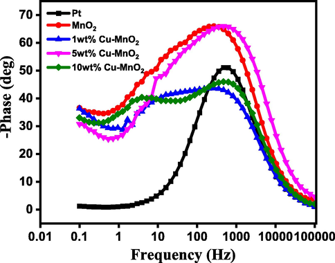
Bode phase plots of dummy cells fabricated with Pt, MnO2, 1 wt% Cu-MnO2, 5 wt% Cu-MnO2, and 10 wt% Cu-MnO2 CEs.
To determine exchange current density (current at zero overpotential), Tafel polarization experiments were conducted for thin layer electrodes. Tafel polarization of the dummy cells has been plotted to further analyze the electrocatalytic behaviour of CEs. For that, dummy cells have been fabricated using two identical electrodes coated with Pt and Cu doped MnO2 samples by plotting logarithmic current density as a function of voltage. The higher exchange current density (J0) has been observed (Fig. 7, Table 1) for the Pt CE (1.17 mAcm−2) which is well supported by the lower RCT value compared to that of the 10 wt% Cu doped MnO2 CE (0.055 mAcm−2) indicating better electrocatalysts for good reaction kinetics.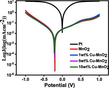
Comparison of Tafel polarization curve of Pt with respect to MnO2, 1 wt% Cu-MnO2, 5 wt% Cu-MnO2, and 10 wt% Cu-MnO2 CEs.
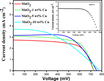
The fabricated solar cells of type FTO/TiO2/N3dye/liquid electrolyte/copper doped MnO2/FTO were analyzed under 0.85 Sun (85 mW cm−2, AM 1.5 G solar simulator; Refer to supporting information for experimental procedure toward the fabrication of solar cells). The open-circuit voltage (Voc), short-circuit current (Isc), fill factor (FF), and PCE (η) was calculated from the measured J-V curves (Fig. 8) using the AUTOLAB12/FRA2 PGSTAT302N model.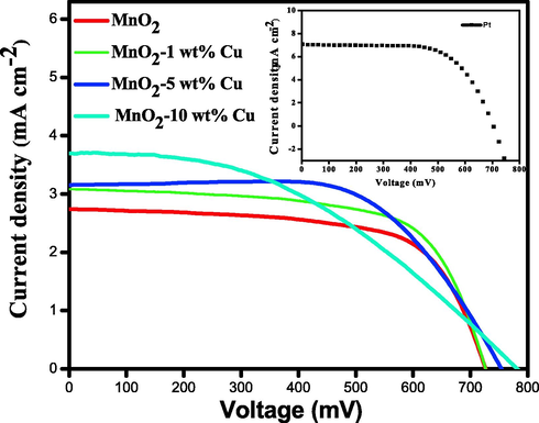
I-V characteristics of DSSCs fabricated with Pt, MnO2, 1 wt% Cu-MnO2, 5 wt% Cu-MnO2, and 10 wt% Cu-MnO2 CEs.
The device fabricated with pristine MnO2 CE showed VOC of 724 mV, ISC of 2.71 mA/cm2, FF of 0.53, and a power conversion efficiency of 1.21%. 1 wt% Cu doped MnO2 showed enhanced % PCE of 1.4 compared with MnO2 CE with VOC of 726 mV, ISC of 3.05 mA/cm2, and improved FF of 0.54. 5 wt% Cu doped MnO2 CE showed VOC of 754 mV, ISC of 3.17 mA/cm2, FF of 0.52, and % PCE of 1.47. 10 wt% Cu doped MnO2 CE showed the best VOC of 781 mV, ISC of 3.69 mA/cm2, FF of 0.50, and % PCE of 1.7. The DSSC fabricated with Pt CE showed VOC of 780 mV, ISC of 6.8 mA/cm2, FF of 0.43, and % PCE of 5.83. These results highlight that Cu doped MnO2 is far better catalytic activity compared to pristine MnO2. (Table 2).
CE
VOC (mV)
ISC (mA/cm2)
FF
PCE%
RS (Ω cm2)
RCT (Ω cm2)
τ1 (ms)
Pt
780
14.8
0.43
5.83
56.13
96.02
0.18
MnO2
724
2.71
0.53
1.21
35.07
184.34
0.79
1 wt% Cu- MnO2
726
3.05
0.54
1.40
21.52
102.26
1.04
5 wt% Cu- MnO2
754
3.17
0.52
1.47
21.14
131.26
0.59
10 wt% Cu- MnO2
781
3.69
0.50
1.70
20.31
108.97
0.79
The Nyquist plots of fabricated DSSCs with Pt, MnO2, 1 wt% Cu-MnO2, 5 wt% Cu-MnO2, and 10 wt% Cu-MnO2 CEs were shown in Fig. 9(A) (Table 2). The doped samples were found to have lower RCT than pure MnO2 samples indicating that the resistance for charge transfer got reduced. A lower RCT value illustrates less overpotential is required for the electron transport between the electrolyte and CE indicating a higher tri-iodide reduction (I-/I3-) and hence high fill factor.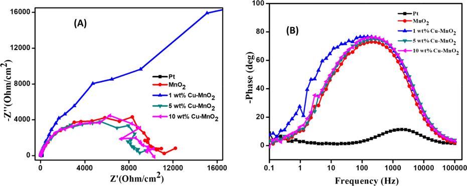
Nyquist (A) and Bode phase (B) plots (under dark) of DSSCs fabricated with Pt, MnO2, 1 wt% Cu-MnO2, 5 wt% Cu-MnO2, and 10 wt% Cu-MnO2 CEs.
In DSSCs, after electron injection from dye molecule into TiO2, there is three possible recombination reactions with the electron acceptors viz. oxidized dye molecule, oxidized electrolyte species, and electron scavenger contaminants in the system. But the recombination reaction of the electron with the oxidized dye molecule is often least considered because this recombination is found to be slower (in the range of 10-4 s) than the regeneration of the dye molecule (10-6 s) by the iodide ion [Bisquert et al. (2004)]. Hence, the primary recombination reaction is between TiO2 and the oxidized ions in the electrolyte solution. Here, the electron lifetime is calculated using the formula τ = 1/2πf, where the frequency is obtained from the Bode plot under illumination conditions at open circuit voltage. The Bode phase plot of the fabricated DSSCs with Pt, MnO2, 1 wt% Cu-MnO2, 5 wt% Cu-MnO2, and 10 wt% Cu-MnO2 CEs was shown in Fig. 9(B). From the Bode phase plot, the electron lifetime can be calculated which illustrates Cu doped MnO2 samples are better than pristine MnO2 (Table 2). The device fabricated with Pt CE showed the lower electron lifetime (0.18 ms) compared to 10 wt% Cu doped MnO2 CE (0.79 ms) suggests decreased electron transfer at TiO2 layer makes Pt CE less efficient for dye regeneration. While, the longer electron lifetime of Cu doped MnO2 CE strongly supports the efficient dye regeneration due to fast electron transfer evidencing the superior electrocatalytic activity. The device fabricated with Pt CE showed the lowest RCT value of 96.02 Ω cm−2 suggesting the fast electron transfer process at CE/electrolyte interface.
Further, a comparable table reflection the improvement with a novel CE are presented in Table 3 illustrate that the initial results of copper doped MnO2 are found satisfactory. This is because in the case of copper doped MnO2, the added copper ion leads to increase the amount of Mn3+ at the surface and in turn improves the catalytic activity. Besides, added copper dopant increased the covalent nature of Mn-O bonds and results in stabilization and faster kinetics rate of electrode. All these factors may responsible for the improvement of efficiency upon compared to pristine MnO2.
CE
VOC (mV)
ISC (mA/cm2)
FF
PCE%
Ref
10 wt% Cu- MnO2
781
3.69
0.50
1.70
This work
α-MnO2 nanorods
750
14.7
0.38
4.1
Ahmad et al. 2017
MnO2 -carbon nanofiber composite
783
16.15
0.70
8.86
Li et al. 2017
MnO2 -NiO composite
830
0.3
0.84
0.21
Kakroo et al. 2020
Fe3C-1 %Cu
700
12.72
0.61
5.46
Cai et al. 2017
Cu:TiO2/TiO2
1073
7.52
0.55
4.87
Ünlü and Özacar 2020
4 Conclusions
MnO2 and copper doped MnO2 nanoparticles have been successfully produced by the hydrothermal method. The formation of the tetragonal crystal structure of α-MnO2 and its copper doped versions was established by XRD analysis. The electrochemical characterization of MnO2 and copper doped MnO2 nanoparticles show the electrocatalytic property of the respective electrodes toward the reduction of I3- ions. Even though the samples do not show the distinct oxidation and reduction peaks in the CV study, the DSSC devices fabricated with MnO2 and copper doped MnO2 CEs behave like diodes under dark (no light is present). Among the fabricated DSSCs 10 wt% Cu doped MnO2 cathodes yield the highest energy conversion efficiency of 1.7% than the pristine MnO2 which had only 1.21% PCE. Further study regarding the choice of a material having electrocatalytic activity as good as Pt may lead to the fabrication of low-cost Pt-free DSSCs.
Acknowledgments
The authors are thankful to the Deanship of Scientific Research at Najran University for funding this work under the National Research Priorities funding program (NU/NRP/SERC/11/9).
Declaration of Competing Interest
The authors declare that they have no known competing financial interests or personal relationships that could have appeared to influence the work reported in this paper.
References
- Hydrothermally grown α-MnO2 nanorods as highly efficient low-cost counter-electrode material for dye-sensitized solar cells and electrochemical sensing applications. Electrochim. Acta. 2017;252:549-557.
- [Google Scholar]
- Synthesis of copper-doped MnO2 electrode materials by one-step hydrothermal method for high performance. Acta Chim. Slov.. 2019;66:584-591.
- [Google Scholar]
- Ni-doped TiO2/TiO2 homojunction photoanodes for efficient dye-sensitized solar cells. Int. J. Energy Res. 2022 In press
- [CrossRef] [Google Scholar]
- Opaque Pt counter electrodes for dye-sensitized solar cells. Int. J. Energy Res.. 2022;46:6543-6552.
- [Google Scholar]
- Bisquert, J., Cahen, D., Hodes, G., Rühle, S., Zaban, A., 2004. Physical Chemical Principles of Photovoltaic Conversion with Nanoparticulate, Mesoporous Dye-Sensitized Solar Cells. J. Phys. Chem. B, 108, 8106-8118.
- Copper-doped Iron carbide as counter electrodes for dye-sensitized solar cells. Int. J Electrochem. Sci.. 2017;12:8421-8431.
- [Google Scholar]
- Dye-sensitized solar cells with a conversion efficiency of 11.1%. Jpn. J. Appl. Phys.. 2006;45:638-640.
- [Google Scholar]
- Enhanced performance of dye-sensitized solar cell with thermally stable natural dye-assisted TiO2/MnO2 bilayer-assembled photoanode. Mat. Renew. Sus. Energy. 2020;9:25-1-25-11.
- [Google Scholar]
- Role of Cu-ion doping in Cu-α-MnO2 nanowire electrocatalysts for the oxygen reduction reaction. J. Phy. Chem. C. 2014;118:17342-17350.
- [Google Scholar]
- Cyclic voltammetrically prepared copper-decorated MnO2 and its electrocatalysis for oxygen reduction reaction (ORR) Int. J. Electrochem. Sci.. 2010;5:72-87.
- [Google Scholar]
- Metal carbides and nitrides as potential catalysts for hydroprocessing. Appl. Catal.. 2003;40:1-28.
- [Google Scholar]
- Review on transition metal compounds-based counter electrode for dye-sensitized solar cells. J. Energy Chem.. 2018;27:703-712.
- [Google Scholar]
- A counter electrode based on hollow spherical particles of polyaniline for a dye-sensitized solar cell. J. Mater. Chem.. 2012;22:14727-14733.
- [Google Scholar]
- Spherical polypyrrole nanoparticles as a highly efficient counter electrode for dye-sensitized solar cells. J. Mater. Chem.. 2011;l21:8146-8151.
- [Google Scholar]
- Highly ordered TiN nanotube arrays as counter electrodes for dye-sensitized solar cells. Chem. Commun.. 2009;44:6720-6722.
- [Google Scholar]
- Nanostructured MnO2 as electrode materials for energy storage. Nanomaterials. 2017;7:396.
- [Google Scholar]
- Electrodeposited MnO2-NiO composites as a Pt free counter electrode for dye-sensitized solar cells. J. Electro. Mater.. 2020;49:2197-2202.
- [Google Scholar]
- Reactively sputtered nickel nitride as electrocatalytic counter electrode for dye- and quantum dot-sensitized solar cells, sensitizers, electrolytes, and counter electrodes. Sci. Rep.. 2015;5(10450)
- [CrossRef] [Google Scholar]
- Fabrication and characterization of carbon-based counter electrodes prepared by electrophoretic deposition for dye-sensitized solar cells. Nanoscale Res. Lett.. 2012;7:53.
- [Google Scholar]
- Enhanced photovoltaic properties of a cobalt bipyridyl redox electrolyte in dye-sensitized solar cells employing vertically aligned TiO2 nanotube electrodes. J. Phys. Chem. C. 2011;115:19979-19985.
- [Google Scholar]
- Electrodeposited Pt for cost-efficient and flexible dye-sensitized solar cells. Electrochim. Acta. 2006;51:3814-3819.
- [Google Scholar]
- Synthesis of highly effective MnO2 coated carbon nanofibers composites as low cost counter electrode for efficient dye-sensitized solar cells. J. Power Sources. 2017;363:9-15.
- [Google Scholar]
- Copper doped hollow structured manganese oxide mesocrystals with controlled phase structure and morphology as anode materials for lithium ion battery with Improved electrochemical performance. ACS Appl. Mater. Interfaces. 2013;5:10975-10984.
- [Google Scholar]
- Novel counter electrode catalysts of niobium oxides supersede Pt for dye-sensitized solar cells. Chem. Commun.. 2011;47:11489-11491.
- [Google Scholar]
- Synthesis of single-crystal tetragonal α-MnO2 nanotubes. J. Phys. Chem. C. 2008;112:12594-12898.
- [Google Scholar]
- Synthesis and property of copper-impregnated α-MnO2 semiconductor quantum dots. Langmuir. 2018;34:12702-12712.
- [Google Scholar]
- Size engineered Cu-doped α-MnO2 nanoparticles for exaggerated photocatalytic activity and energy storage application. Mat. Res. Bull.. 2019;115:159-169.
- [Google Scholar]
- Counter electrodes for DSC: application of functional materials as catalysts. Inorg. Chim. Acta. 2008;361:572-580.
- [Google Scholar]
- Enhancement of the efficiency of dye-sensitized solar cell by utilizing carbon nanotube counter electrode. Scr. Mater.. 2010;62:148-150.
- [Google Scholar]
- Dissolution of platinum in methoxy propionitrile containing LiI/I2. Sol. Energy Mater. Sol. Cells. 2000;63:267-273.
- [Google Scholar]
- Influence of zirconium dioxide and titanium dioxide binders on the photovoltaic performance of dye sensitized solar cell tungsten carbide nanorods based counter electrode. Electrochim. Acta. 2016;211:375-384.
- [Google Scholar]
- Sarker, S., Ahammad, A. J. S., Seo, H. W., Kim D. M., 2014. Electrochemical Impedance Spectra of Dye-Sensitized solar cells: Fundamentals and Spreadsheet Calculation. Int. J. Photoenergy. 2014, 851705 (1-17).
- A review on counter electrode materials in dye-sensitized solar cells. J. Mater. Chem. A. 2014;2:4474-4490.
- [Google Scholar]
- Effect of cu and Mn amounts doped to TiO2 on the performance of DSSCs. Sol Energy. 2020;196:448-456.
- [Google Scholar]
- Platinum-free dye-sensitized solar cells by flower-like mixed-phase CoxSy/NixSy/MoxSy composites. New J. Chem.. 2021;45:1967-1976.
- [Google Scholar]
- Facile synthesis of tungsten carbide nanorods and its application as counter electrode in dye-sensitized solar cells. Mat. Sci. in Semicon. Proc.. 2015;39:292-299.
- [Google Scholar]
- The search for efficient electrocatalysts as counter electrode materials for dye-sensitized solar cells: mechanistic study, material screening and experimental validation. NPG Asia Mater.. 2015;7:e226
- [Google Scholar]
- Manganese oxide-based materials as electrochemical supercapacitor electrodes. Chem. Soc. Rev.. 2011;40:1697-1721.
- [Google Scholar]
- Wu, J., Lan, Z., Lin, J., Huang, M., Huang, Y., Fan, L. Luo, G., Lin, Y.,Xie, Y., Wei, Y., 2017. Counter electrodes in dye-sensitized solar cells. Chem. Soc. Rev., 46, 5975.
- Economical Pt-free catalysts for counter electrodes of dye-sensitized solar cells. J. Am. Chem. Soc.. 2012;134:3419-3428.
- [Google Scholar]
- Economical and effective sulfide catalysts for dye-sensitized solar cells as counter electrodes. Phys. Chem. Chem. Phys.. 2011;13:19298-19301.
- [Google Scholar]
- Improving the rate performance of manganese dioxide by doping with Cu2+. Co2+ and Ni2+ ions. Int. J. Electrochem. Sci.. 2019;14:3673-3683.
- [Google Scholar]
- Efficient iron phosphide catalyst as a counter electrode in dye-sensitized solar cells. ACS Appl. Energy Mater.. 2021;4:10618-10626.
- [Google Scholar]
- A new type of low-cost counter electrode catalyst based on platinum nanoparticles loaded onto silicon carbide (Pt/SiC) for dye-sensitized solar cells. Phys. Chem. Chem. Phys.. 2013;15:4286-4290.
- [Google Scholar]
- Hierarchical micro/nano-structured titanium nitride spheres as a high-performance counter electrode for a dye-sensitized solar cell Hierarchical micro/nano-structured titanium nitride spheres as a high-performance counter electrode for a dye-sensitized solar cell. J. Mater. Chem. A. 2012;22:6067-6071.
- [Google Scholar]
- Notable catalytic activity of oxygen-vacancy-rich WO2.72 nanorod bundles as counter electrodes for dye-sensitized solar cells. Chem. Commun.. 2013;49:7626-7628.
- [Google Scholar]
- The basic research on the dye-sensitized solar cells. J. Clean Energy Technol.. 2015;3:382-387.
- [Google Scholar]
Appendix A
Supplementary material
Supplementary data to this article can be found online at https://doi.org/10.1016/j.arabjc.2022.104068.
Appendix A
Supplementary material
The following are the Supplementary data to this article:Supplementary Data 1
Supplementary Data 1


