

Translate this page into:
Design and characteristic analysis of flame cutting nozzles for ultralarge-thickness steel ingots
⁎Corresponding authors. 45309249@qq.com (Haonan Yu), wangzc@nepu.edu.cn (Zunce Wang)
-
Received: ,
Accepted: ,
This article was originally published by Elsevier and was migrated to Scientific Scholar after the change of Publisher.
Abstract
The cutting thickness of the flame cutting nozzle mainly depends on the characteristics of the cutting oxygen jet, and in the process of designing and manufacturing a flame cutting nozzle with an ultralarge thickness, it is impossible to carry out multiple experiments to optimize the design due to the difficulty in testing, safety, manufacturing cost, environmental pollution, and other problems. In this paper, the Laval-type cutting oxygen orifice channel was first designed by theoretical calculation, the pressure, velocity, Mach number, and density distribution characteristics of the cutting oxygen jet were investigated by numerical simulation, and the reliability and adaptability of the numerical simulation results were verified by experiments. Then, the numerical simulation comparison and estimation method of jet characteristics with the general-purpose G301-7# nozzle was used to study the cutting oxygen orifice channel of the ultralarge thickness flame cutting nozzle. The results show that under the condition of a 19 mm throat diameter and 10 atm inlet pressure, it was estimated that the length of cutting oxygen flow from the design nozzle can reach 1800 mm and the cutting thickness can reach 2500 mm based on the density value; the length of cutting oxygen flow can reach 2000 mm and the cutting thickness can reach 3800 mm based on the velocity value; the length of cutting oxygen flow can reach 1600 mm according to the value of the oxygen quality fraction; and the cutting thickness can reach 2800 mm based on the oxygen mass fraction content. Finally, trial production of the nozzle design, verification of the cutting test, the nozzle with a cutting thickness of 2500 mm at an oxygen pressure of 7 atm, and the cutting quality were all good.
Keywords
Laval nozzle
Cutting oxygen jet
Ultrathickness flame cutting
Cutting oxygen orifice channel design
Numerical simulation

Nomenclature
- m
-
mass
- M
-
molar mass
- P
-
Pressure
- V
-
volume
- T
-
thermodynamic temperature
- R
-
universal constant
- At
-
throat cross-sectional area
- ṁ
-
mass flow
- p0
-
total pressure of the gas supply
- pe
-
outlet pressure
- pa
-
ambient pressure
- T0
-
total gas temperature
-
volumetric flow rate
- dt
-
throat diameter
- r0
-
stabilizing section radius
- l
-
contraction section length
- re
-
radius of the exit of the contraction section
- r
-
cross-sectional radius
- rt
-
throat radius
- La
-
diffusion segment length
-
velocity vectorand
- u,v,w
-
component of the velocity vector in x, y, z direction
- Sx, Sy, Sz
-
generalized source term of the momentum conservation equation
- k
-
thermal conductivity of the fluid; turbulent kinetic energy
- Sh
-
internal heat source of the fluid
- Φ
-
fraction of mechanical energy converted to thermal energy
- Gk
-
generation term of turbulent kinetic energy k due to mean velocity
- Gb
-
generation term of the turbulent kinetic energy k due to buoyancy
- Ym
-
contribution of pulsation expansion in pressurisable turbulence
- C1ε, C2ε, C3ε
-
empirical constants
- ρ0
-
oxygen density
- µ
-
dynamical viscosity
- ε
-
dissipation rate
- γ
-
specific heat ratio
Greek letter
1 Introduction
In the manufacturing process of casting and forging, the processes of casting sprue and riser removal, as well as cutting in casting forming, are important processes. Commonly used methods for cutting casting risers include mechanical cutting, oxygen-flame cutting, plasma cutting, laser cutting, and waterjet cutting (Bao-Jun et al., 2022; C et al., 2022; Andjela and Dragoljub, 2022; S et al., 2019; Izzet et al., 2011). As industries such as shipping, electric power, petrochemicals, and aerospace continue to develop, the manufacturing of castings and forgings is moving towards larger scales and automation. Oxygen-flame cutting has become the preferred cutting method for removing sprues and risers from large castings.
Oxygen − flame cutting as a traditional thermal cutting process, the history can be traced back to the 1870 s. The principle involves preheating the workpiece to the ignition point of the metal through oxygen-gas combustion. Subsequently, high-speed, high-purity cutting oxygen is used to induce a violent oxidation reaction in the metal workpiece. This reaction releases a significant amount of heat, melting the metal. Simultaneously, the high-velocity, high-energy cutting oxygen jet blown away the molten metal, creating the cutting kerf (Miller, 1916; Liu et al., 2019). As the oxygen chemically combines with the iron exothermically (exothermic reaction), the result is generally referred to as the cutting jet. The cutting jet is always in the center of the tip and instantly starts a rapid oxidation of the steel through the depth of the cut. A tremendous amount of heat is liberated when the high purity oxygen unites with the steel during this reaction. If carried through to completion, you have three balanced chemical equations as a result of this reaction (Ch et al., 2018):
Fe + ½O2 → FeO + Heat (267 kJ) First Reaction
3Fe + 2O2 → Fe3O4 + Heat (1120.5 kJ) Second Reaction
2Fe + 2½O2 → Fe2O3 + Heat (823.4 kJ) Third Reaction
At present, oxygen flame cutting plays an irreplaceable role in cutting mild steel and low alloy steel plates, especially in cutting large thickness ingots, its cutting thickness can exceed 1200 mm, surpassing other thermal cutting methods (Górka & Poloczek, 2018).The cutting nozzle is an essential component in oxy-flame cutting technology, comprising channels for the cutting oxygen orifice, preheated oxygen orifice, and preheated natural gas orifice (Jo et al., 2024). A high-quality cutting nozzle enhances cutting quality, conserves material, reduces deformation, and minimizes residual amounts for subsequent machining (Bae et al., 2018). Particularly in medium-thick plate cutting, Insufficient heat inputs can make cutting difficult, higher heat inputs can result in larger heat-affected zones and residual stresses, which increases the risk of cracking during the process (Jokiaho et al., 2019). Thus, the design and manufacturing level of the cutting nozzle are crucial for cutting quality and torch utility. Among the factors affecting flame cutting, the cutting oxygen has to not only participate in the ferro-oxygen reaction while maintaining sufficient momentum to blow the molten metal away from the cutting kerf. Therefore, the faster the flow rate and the better the form of the cutting oxygen jet from the cutting nozzle, the longer its length and the higher the purity of the oxygen at the position of the rated cutting thickness. (Bae et al.,2018). Therefore, optimizing the structure of the cutting oxygen orifice channel to improve the flow characteristics of the jet is key to achieving large-thickness flame cutting (YANG et al., 2024). As CNC machining technology advances, researchers increasingly are using Laval channels for cutting oxygen orifices channels. Studies show that the Laval nozzle produces a highly uniform and stable cutting oxygen jet with high dynamic pressure at the outlet. Compared to a typical nozzle, the Laval nozzle generates a longer supersonic flow length with less variation in gas behavior within the flow (Zhang et al., 2016). Jets from the Laval channel have a longer potential core and higher centerline axial velocity for the same outlet momentum (He et al. 2021; Li et al. 2008).
Additionally, the Laval-type cutting oxygen orifice better maintains and controls the flow field morphology of the cutting flame. Through structural regulation of the Laval-type orifice, the size of the heat-affected zone in flame cutting can be effectively controlled (Bae et al., 2016; Jokiaho et al., 2017).
In summary, numerous scholars have contributed extensive research on enhancing the structure of cutting oxygen orifices, jet characteristics, and experimental detection technologies. This body of work establishes the theoretical foundation and directs the research methods and ideas presented in this paper. However, these studies primarily concentrate on the technology of medium-thin plate cutting, with no reports on flame cutting for plates exceeding 2000 mm in thickness. The objective of this paper is to explore the structural design and flow characteristics of the orifice within flame cutting nozzles for steel ingots ranging from 2000 mm to 3500 mm in thickness. Achieving this will facilitate the automation of ultra-large ingot cutting within the 2000 to 3500 mm range, overcome the bottleneck of cutting for risers in the production of large castings and forgings, and provide a theoretical basis for further research on large ingot flame cutting process control technology.
2 Experimental setup and methods
2.1 Materials
The ingot sample YB-70 (50Cr5NiMoV), produced by China First Heavy Industries Group Limited (Qiqihar, China), has a diameter of φ2500 mm. This particular alloy steel is characterized by high strength and toughness, as well as excellent mechanical properties and wear resistance. It maintains its strength and toughness even under conditions of elevated temperature and pressure. Primarily, it is used for manufacturing components for aerospace and petrochemical equipment. Its chemical composition is detailed in Table 1.
Element
C
Si
Mn
P
S
Cr
Ni
Mo
V
Composition(wt%) (wt%)
0.50 ∼ 0.60
0.40 ∼ 0.80
0.50 ∼ 0.80
≤0.01
≤0.01
4.50 ∼ 5.50
0.40 ∼ 0.60
0.40 ∼ 0.80
≤0.03
2.2 Semi-automatic flame cutting machine
The semi-automatic flame cutting machine, model CG1-30, and the cutting nozzle type G301-7#, are both supplied by Shanghai Huawei Welding & Cutting Machinery Co. These devices served as the benchmark for cutting 300 mm thick steel plates and the associated measurements, as depicted in Fig. 1. The design parameters for the cutting nozzle type G301-7# cutting nozzle are given in Table 2.
Semi-automatic flame cutting machine and G01-300 cutting nozzl.
Nozzle Model
Throat Diameter
d/mmInlet Pressure
P0/MPaTheoretical Flow
Qt/(L·h−1)Critical Velocity
v/(m·s−1)Cutting Thickness
Δ/mm
G301-7#
3
0.6
8647
340
300
2.3 The flame cutting Machine for the ultralarge-thickness steel ingots
The laboratory has independently developed the GH-2500-LM6.5 and GH-3500-LM6.5 flame cutting equipment for ultralarge-thickness steel ingots. The system, designed for ultralarge-thickness cutting, comprises a liquid oxygen station, a propane gas station, a pressure reduction system, and an energy regulation system. According to Fig. 2, the oxygen supply maintains a purity of at least 99 %, with a maximum pressure of up to 1.0 MPa and a flow rate of up to 1000 m3/h under working conditions. The propane gas supply exceeds a purity of 95 %, with a maximum pressure of up to 0.6 MPa and a peak flow rate of 140 m3/h.
The Flame Cutting Machine for the ultralarge-thickness steel ingots.
2.4 Schlieren method
The Schlieren method was employed to visualize the shape and extent of the cutting oxygen flow field. As depicted in Fig. 3, a Schlieren apparatus, featuring two concave mirrors, was arranged for this experiment. The oxygen and propane gas supplies were connected to the gas pressure and flow test stand, and subsequently to the isobaric torch. A nozzle inlet pressure of 5 atm was maintained throughout the experiment, based on the design pressure of the G301-7# nozzle. For the Schlieren setup, a high-power white LED lamp with an output of 120 W served as the light source. This light was focused through a condenser lens and passed through a 2 mm diameter slit. The concave mirrors used in this configuration were axially parabolic, with a diameter of 200 mm and a focal length of 2030 mm, and they exhibited a reflectivity exceeding 90 %. The light source and focusing nut were adjusted until the rectangular slit was precisely at the focus of the main lens. By manipulating the position of the knife edge and the light knife adjustment knob, the image on the screen could be uniformly brightened or darkened, indicating that the knife edge was also at the focus of the main lens. A video or photograph was then captured and the cutting oxygen flow rate was recorded.
Schematic diagram of Schlieren method and Visible oxygen flow Length Test.
Ignite the preheating flame at the designated pressure and adjust it to a neutral flame. Subsequently, activate the cutting oxygen valve and capture the steady-state visible cutting oxygen flow's shape using a high-speed video camera. Measure the length of the visible oxygen flow against a standard length scale.
3 Numerical simulation
As shown in Fig. 4 that the cutting flame mainly includes cutting oxygen, premixed flame and cutting oxygen curtain. Cutting flames mainly include cutting oxygen, premixed flame and cutting oxygen curtain. The shape of the oxygen ejection at the nozzle outlet improves with higher speed, resulting in longer cutting oxygen flow and higher oxygen purity at the desired cutting thickness position. Therefore, the design of the cutting oxygen orifice channel has a significant effect on the cutting oxygen jet. In addition, the combination of premixed flame and cutting oxygen curtain improves the length of the cutting oxygen jet, maintains the purity of the cutting oxygen and increases the stability of the preheating flame.
Oxygen-flame cutting morphology.
3.1 Flow state of the cutting oxygen orifice channel
The Laval nozzle is a tube that contracts and then diffuses to achieve and generate supersonic airflow, consisting of three parts: a contraction section, a throat section and an expansion section (Li et al., 2008), as shown in Fig. 5. The Laval nozzle causes the gas to compress and then rapidly expand, reaching supersonic speeds as it exits the nozzle for cutting purposes.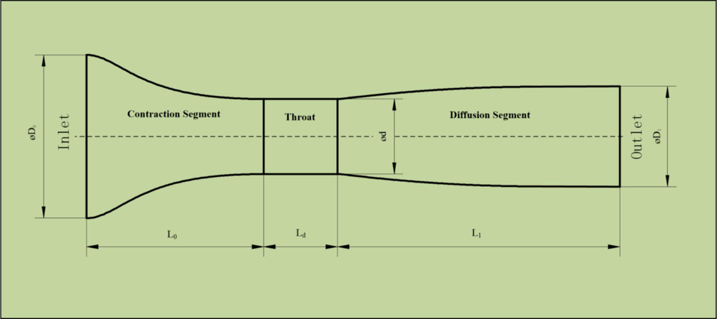
Schematic diagram of Laval nozzle.
3.1.1 Numerical setup
For supersonic isentropic flow in a quasi-one-dimensional nozzle, the Mach number and velocity increase with the nozzle size. In contrast, other variables, such as pressure and temperature, decrease (Bian et al., 2018). There is a subsonic region in front of the throat and a supersonic region behind the throat.The relationship between the Mach number and the area ratio of the airflow at any cross-section A in a Laval nozzle in an adiabatic isentropic flow is as follows:
When the flow velocity at the throat reaches the speed of sound, the mass flow ṁ through the oxygen channel can be expressed by Eq. (2)(Qijia et al., 2024).
When the outlet pressure pe of the oxygen duct is equal to the ambient pressure pa, its operating condition is the best operating condition. At this point, the relationship between the pressure ratio and Mach number Ma is shown in Eq. (3).
In Eq. (1)-(3), the gas constant R, the gas specific heat ratio γ, and the total gas temperature T0 are known. The design outlet pressure pe, which is generally equal to the ambient pressure, is also known.
3.2 Diffusion-type high-speed nozzle cutting oxygen orifice channel design
3.2.1 Nozzle throat
The throat of the Laval nozzle is the core part of the gas accelerating from subsonic to supersonic speeds. It has been found that for a given inlet pressure and outlet diameter, the maximum Mach number at the outlet decreases as the throat width increases(Urionabarrenetxea et al., 2022). In other words, the throat width should be reduced if a higher exit velocity of the flow is required, and the numerical results were verified experimentally using the Particle Image Velocimeter (PIV) technique. The relationship between the flow rate
at standard oxygen conditions and the throat diameter dt and the design pressure p0 of the cutting oxygen can be approximated at room temperature.
Substituting Eq. (4) into Eq. (5) gives:
The symbolic units in the above formulae are all in the International System of Units (SI), the flow unit is m3/s, the pressure unit is Pa (absolute pressure), the unit of dt is m, and the temperature unit is K.
If the unit of dt is mm, the unit of
is m3/h, the unit of pressure is kgf/cm2, and the temperature T0 is 273 K, then:
t is important to note that 1 atm is 101325 Pa, and 1 kgf/cm2 is 98000 Pa. Simplifications have been made between the different formulae, and there will be some error, approximately 3 %, which is generally acceptable.
3.2.2 Inlet designs
The geometry at the inlet can improve the aerodynamic and thermodynamic parameters (Lakzian et al., 2022). Before entering the inlet of the contraction section, the cutting oxygen must flow through the orifice channel of the stabilizing section with the same cross section, and the diameter of the stabilizing section (the diameter of the inlet of the contraction section) Φd0 depends on the diameter of the throat Φdt, generally d0 ≥ dt. In fact, the smallest diameter cannot be smaller than dt. The length of the stabilizing segment is usually approximately 10 times the diameter of the stabilizing segment, i.e., 10d0.
The inlet constriction section can be designed as a taper consisting of straight lines and arcs, or it can be calculated using the Witocinski curve formula, and this profile can be used to obtain a uniform one-dimensional flow field in the throat.
3.2.3 Outlet design
The diffusion section of the Laval nozzle is the key to achieving supersonics.The outlet of the cutting oxygen orifices channel are generally conical or double-arc profiles, where the double-arc profiles are proposed based on the radial flow conditions, which are very close to the ideal flow field profiles and can be used to obtain relatively good flow field morphology in a simple way.
A double arc means that the inner surface of the diffusion section of the nozzle consists of two arcs, as shown in Fig. 6. The first arc makes up the surface of the throat area, the center of which is located in the critical section of the throat, and its radius Rr is the initial diffusion arc radius of the diffusion section, which is generally assumed to be Rr = 2rt (rt is the radius of the throat of the cutting oxygen channel). The second arc is the supersonic zone profile with radius R0, and the two arcs are tangent to point A. R0 is the radius of the larger arc of the double arc profiles, point (X0, Y0) is the coordinates of the center of the larger arc of the circle (with the point on the axis of the starting position of the diffusion section of the throat as the origin), Re is the radius of the exit section of the oxygen channel, Ae is the diffusion half-angle of the exit of the oxygen channel, Af is the initial maximum diffusion half-angle, and La is the total length of the diffusion section of the cutting oxygen channel.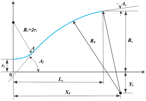
Cutting oxygen orifices for double arc profile.
Knowing rt and Re and given Rr, Ae and Af, all the parameters shown in Fig. 6 can be determined. The calculation process is as follows.
-
The coordinates of point A(x1,y1) of the tangent of the two arcs are calculated from the angles Rr and Af.
-
All points on the first arc satisfy Eq. (10).
The y-coordinate of the corresponding point on the arc can be calculated by taking x-values at regular intervals from the origin.
-
The second arc radius is calculated.
-
The coordinates of the center of the second arc are calculated.
-
The total length La of the diffusion segment is calculated.
-
The points on the second arc of the circle satisfy Eq. (14).
Taking values at regular intervals from point A(x1,y1) up to length La gives the y coordinate of the corresponding point on the arc. If the outlet has a straight line segment, the corresponding x and y coordinates from the straight line segment should be calculated.
Finally, the coordinates of each point are recorded and traced to obtain the profile curve of the diffusion section of the oxygen channel designed by the double arc method.
3.3 Governing equations
The flow of cutting oxygen through the nozzle channel is subject to the laws of conservation of mass, conservation of momentum and conservation of energy. In this paper, the Reynolds Averaged Navier-Stokes (RANS) method is chosen to solve the flow control equations for the Laval nozzle flow, and the Reynolds transport term is closed using the realistic model based on the vortex viscosity assumption. The turbulence in the method is divided into two parts, the mean motion and the pulsation motion, and the variables within the flow field are calculated by the time-averaged and pulsed values together. The time-averaged Navier-Stokes control differential equation for a compressible flow expressed in tensor form on the Reynolds time-averaged method is as follows (Zhang et al., 2022a; Zhang et al., 2022b; Dong et al., 2019).
3.3.1 Continuity equation
The law of conservation of mass for cutting oxygen jets can be stated as follows: the increase in mass of a fluid microelement per unit time is equal to the net mass flowing into that microelement during the same time interval. Following this law leads to Eq.(16)(Launder and Spalding, 1972; M and M, 2010).
3.3.2 Conservation of momentum equation
The conservation of momentum equation can be expressed as the rate of change of the momentum of the fluid in a microelement with time being equal to the sum of the various external forces acting on the microelement. This law is actually Newton's second law. This law can be used to derive the conservation of momentum equation in three directions.
3.3.3 Energy conservation equation
The law of conservation of energy can be expressed as the rate of increase of energy in a microelement body equaling the net heat flux into the microelement body plus the work done on the microelement body by volumetric and surface forces. This law is actually the first law of thermodynamics, and the introduction of Fourier's law of thermal conductivity leads to an energy equation expressed in terms of fluid enthalpy and temperature (Kai et al., 2018; M and M, 2009)
In Eq.(15–17),
and
are the mean velocity components in the ith and jth directions, respectively.
and
are the fluctuating velocity components in the ith and jth directions, respectively.
means the heat of chemical reaction and volumetric heat source. E is the total energy and
is the viscous stress.
represents the Reynold stress to evaluate the turbulent effect, and could be expressed as Eq. (18) referring to the Boussinesq approximation:
3.3.4 Turbulence model
The realisable turbulence model was chosen to determine the flow field within the model, where the turbulent kinetic energy k and the turbulent dissipation rate ε(m2·s−3) are calculated as follows(Zhang et al., 2022a; Zhang et al., 2022b).
3.4 Model validation
The flow characteristics such as velocity, pressure and density of the cutting oxygen jet are the focus of this study. To verify the accuracy of the numerical model, numerical simulations were carried out for the nozzle type G301-7# nozzles and verified by the experiments shown in Fig. 3. Details related to the boundary and initial conditions can be found in Table 3.
Properties
Values
Viscous model
Realizable k-e, SWF
Material
O2(ideal-gas)
gauge Total Pressure
500,000 Pa
Operating Pressure
0 Pa
Outlet pressure
101,325 Pa
Fig. 7 shows the results of numerical simulations of the distribution of the axial velocity of the jet in the cutting nozzle along the centreline of the nozzle at different inlet pressures. The axial jet velocity at the outlet is 336 m/s, which is essentially the same as the design critical velocity. The gas pressure and flow test bench show an actual flow value of 9033 L/h.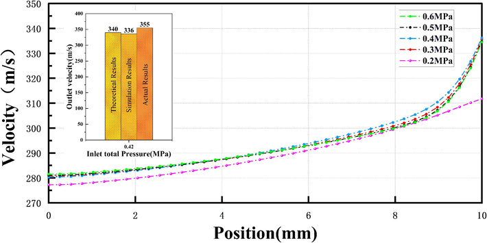
G301-71 Cutting oxygen orifice channel speed curve.
From the flow expression for a straight pipe:
The actual flow velocity at the nozzle outlet is 355 m/s according to Eq. (21). The error between the simulation velocity value and the theoretical results is 1.17 %, and between the simulation and the experimental results is 5.35 %. Demonstration of the credibility of the present model in nozzle cutting oxygen jet characteristics.
By comparing the actual flow field pattern of the type G301-7# cutting nozzle with the simulation results, the simulated value of cutting oxygen cold flow length is 145 mm, and the actual cold flow length is 140 mm; the simulated value of cutting oxygen hot flow length is 190 mm, and the actual hot flow length is about 182 mm. The reliability of this model is demonstrated by the length and morphology of the cutting oxygen flow. As shown in Fig. 8.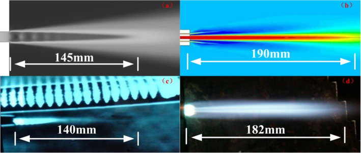
Comparative Verification of Cutting Oxygen Flow Length and Morphology.
3.5 Simulation details
To investigate the characterization of the cutting oxygen nozzle channel, Laval-type cutting oxygen nozzles are designed, and numerical simulation is performed to analyze the cold flow field of the oversized thickness cutting nozzle orifice channel, the structure of which is shown in Fig. 9. To improve the accuracy of the simulation results, the computational domains are all structured meshes, the wall of the cutting oxygen orifice channel and the throat of the nozzle and outlet in the region were finely meshed to capture gas flow dynamics with higher accuracy. The initial conditions for the calculation are set as follows: density-based axisymmetric steady-state flow field calculations are used, and the turbulence model is the standard k-ω model. The working gas is selected as air, the inlet condition is selected as the pressure inlet, the inlet pressure is 5 atmospheres and the initial temperature is 300 K. The outlet condition is selected as a pressure far-field outlet. The flow field is 1000 mm long and 400 mm wide and is divided into several regions for meshing, as shown in Fig. 10.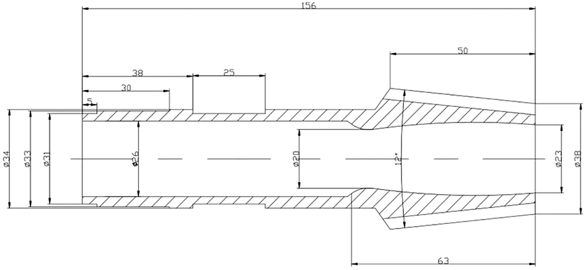
Schematic diagram of cutting-oxygen orifice structure for ultra-thick cutting torch.
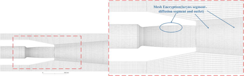
Flow field meshing results.
3.6 Mesh independency test
A numerical simulation was carried out using commercial Computational Fluid Dynamics (CFD) software ANSYS Fluent 2022. The numerical simulation model is based on a pressure-based approach combined with a steady-state model to solve the Reynolds time-averaged equations. The Realizable k-epsilon turbulence model is used to obtain a steady flow field,. The wall condition is a no-slip boundary condition. The solution convergence is determined that the numerical residuals are < 10−6 for the energy and < 10−3 for all the other variables.
To analyze the sensitivity and feasibility of the mesh model, simulations for the cutting oxygen jet are carried out with the following three kinds of mesh levels: coarse mesh (56,206 cells), medium mesh (92,547 cells), and fine mesh (136,169 cells). Fig. 11 shows the axial velocity distribution data of the cutting oxygen jet along the axial center line. Fig. 11 shows that the variation increases as the nozzle distance improves, the average percentage variation of the axial velocity profile calculated with the coarse and medium meshes is above 6.0 pct, and the difference between medium and fine mesh is less than 1.0 pct, which can be considered negligible. Therefore, the medium and fine mesh simulations have little impact on the results. Considering the computational time and resources needed for the numerical simulation process, the simulation results obtained by the medium mesh are used for research and discussion in this paper.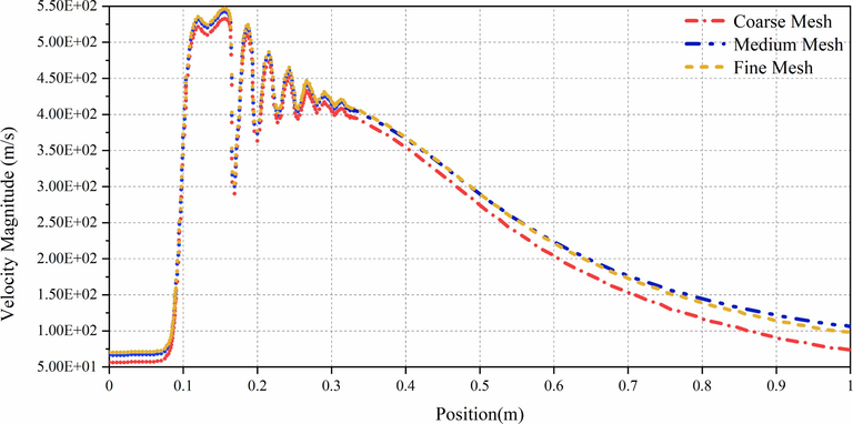
Axial velocity of the cutting oxygen jet with three mesh models.
4 Results and discussion
4.1 Pressure distribution
Fig. 12 shows the cutting oxygen orifice and outlet pressure distribution for the Laval type designed in this paper. To better study the transonic behavior, the inlet pressure was set at 5 atm (the design pressure is 7 atm). When the cutting oxygen reaches the nozzle outlet, its pressure has already expanded below ambient pressure and is in a state of overexpansion, creating a conical shock wave at the nozzle outlet, with the airflow boundary line concave inwards, followed by an expansion wave, and so on, repeatedly and progressively weaker, until the airflow pressure matches the ambient pressure. This characteristic also exists in other parameter distributions.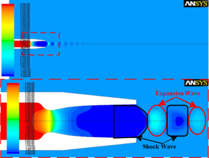
Flow field pressure distribution cloud.
Fig. 13 shows the pressure distribution curve of cutting oxygen along the axis. After passing through the outlet, the shock and expansion waves alternate, and the gas pressure oscillation is weakened. Taking the nozzle inlet as the starting point, the throat is approximately 96 mm, and the nozzle outlet is approximately 156 mm (as shown in Fig. 6). As seen from the graph, the pressure of the cutting oxygen stream at the diffusion segment of the nozzle is already lower than the ambient pressure. When the cutting oxygen jet reaches 400 mm, the airflow pressure is matched to the ambient pressure, and its fluctuation essentially stops.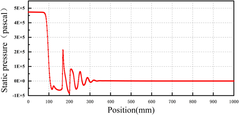
Pressure distribution curve line on axis.
4.2 Velocity distribution
Fig. 14 shows the cutting oxygen orifice and outlet velocity distribution for the Laval type designed in this paper, and the velocity distribution is clearly conical, typical of jets. The fastest velocity of the jet occurs at the exit of the nozzle and reaches 550 m/s. Fig. 15 shows the velocity distribution curve of the cutting oxygen along the axis. At the furthest end of the flow field, 850 mm from the nozzle outlet, the jet velocity is still above 100 m/s. Therefore, the results show that this type of nozzle is favorable for maintaining the flow field velocity as well as the airflow purity.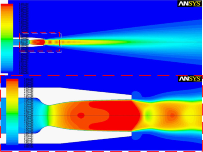
Velocity distribution cloud.
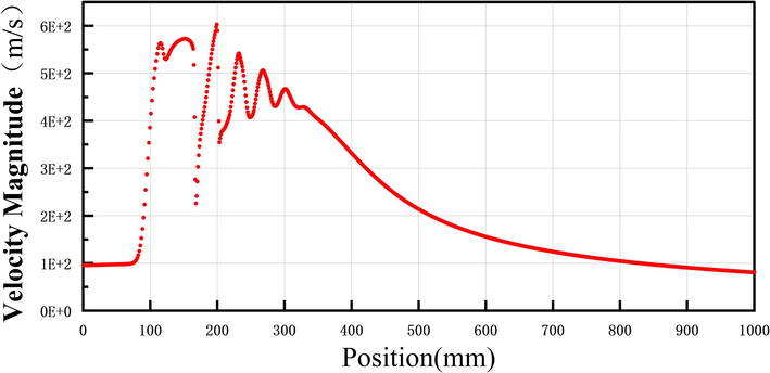
Velocity distribution curve line on axis.
4.3 Mach number distribution
Fig. 16 shows the Mach number distribution of the jet at the nozzle outlet, and the diamond-shaped Mach point is clearly visible in the figure. Fig. 17 shows the magnitude of the Mach number values and the decay on the axis, and the results show that the Mach number distribution is similar to the velocity distribution.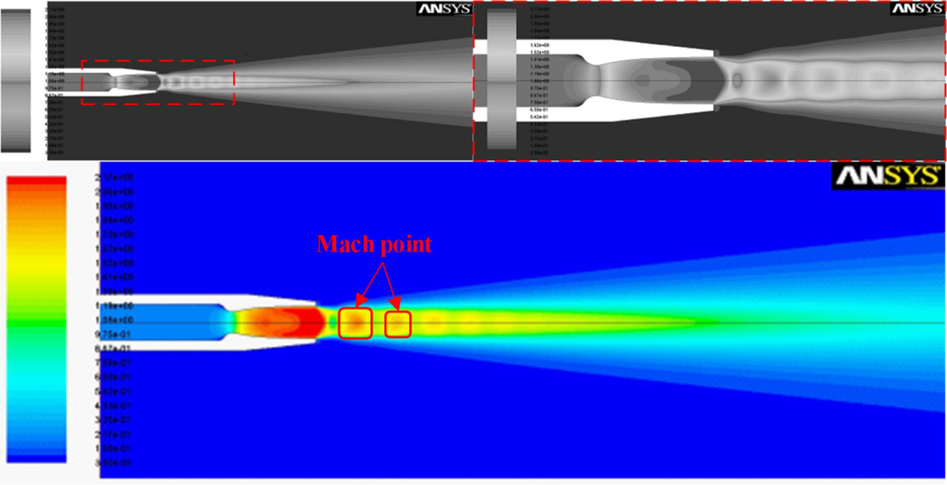
Mach number distribution cloud.
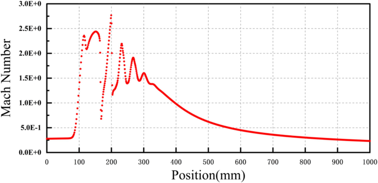
Mach number distribution curve line on axis.
4.4 Density distribution
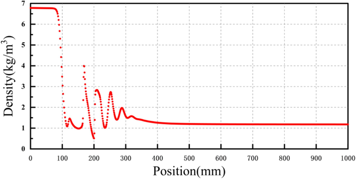
Fig. 18 shows the density distribution of the jet from the nozzle. The cutting oxygen has the highest gas density in the contraction section of the Laval nozzle from the figure. The jet reaches the throat, and the density gradually decreases, reaching a minimum at the outlet. This is because the gas is pressurized in the contraction section of the cutting oxygen orifice, the density increases, and after passing through the throat, the gas begins to expand and increase in velocity, and the density gradually decreases, confirming the results shown in the velocity distribution cloud. Fig. 19 shows that after the jet passes through the outlet, the density of the gas increases and decreases due to alternating excitation and expansion waves until it is equal to the density of the ambient air (1.29 kg/m3).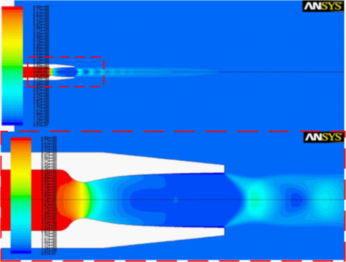
Density distribution cloud.
Density distribution curve line on axis.
5 The comparison of the results between simulations and experiments
The characterisation of the cutting oxygen jet and the activities of oxyfuel gases are important factors in improving the thickness and quality of the cut at the nozzle (Adedayo, 2011). Due to the difficulty of detection, safety, manufacturing cost, gas consumption, pollution and other reasons, the design and trial production of large thickness cutting nozzles cannot be carried out in the process of multiple experiments. Therefore, to minimize the cost and number of experiments, numerical simulation result comparison and prediction study are used to the design and manufacture in advance.
Further analytical study of the numerical simulation of the type G301-7# cutting nozzle shows that at a distance of 182 mm from the nozzle outlet (the length of the cutting oxygen stream) the gas density is about 1.2 kg/m3, the oxygen mass fraction is 0.15–0.16, the velocity is 75–80 m/s. At a distance of 300 mm from the nozzle outlet(the maximum cutting thickness), the gas density is about 1.189 kg/m3, the oxygen mass fraction is about 0.08, and the velocity is about 40 m/s.
5.1 Prediction of cutting thickness for ultrathick cutting nozzle
Using the Laval duct design formulae of this study, a throat diameter of 19 mm and an inlet design pressure of 10 atm were selected for the design of the oversized nozzle cutting oxygen orifice. The computational domain for numerical simulation shown in Fig. 10 was expanded to 400 mm × 4000 mm with a grid of approximately 330,000 cells, a flow rate of 694 m3/h and an initial temperature of 300 K. The inlet gas is selected as oxygen, a mixture of oxygen and nitrogen is used in the computational domain for the calculation, and the result of the calculation of the listed components is the total content of the oxygen component in the gas. These conditions are used for numerical simulation studies and discussions of preliminary research cutting oxygen jets. The numerical simulation study of the jet flow in the designed orifice is carried out based on the above conditions. The cutting thickness and performance of the designed nozzle were predicted by comparison with the gas density, velocity and oxygen mass fraction at the maximum cutting thickness of the type G301-7# cutting nozzle.
5.1.1 Estimated by density value
It is known that the gas density of the type G301-7# cutting nozzle at the length of the cutting oxygen flow is 1.2 kg/m3 (182 mm from the nozzle outlet) and that at the cutting thickness of 300 mm is 1.189 kg/m3. Fig. 20(a-b) shows a contour plot of the gas density along the axis of the design nozzle. It is estimated that the length of cutting oxygen flow from the design nozzle can reach 1800 mm based on the density value of 1.2 kg/m3 at the axis in Fig. 20(a). It is estimated that the cutting thickness with the design nozzle can reach 2500 mm based on the density value of 1.189 kg/m3 at the axis in Fig. 20(b).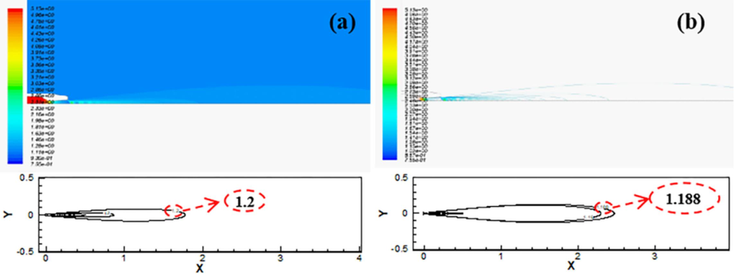
Gas density contour plots.
5.1.2 Estimated by velocity value
It is known from numerical simulation that the gas velocity of the type G301-7# cutting nozzle is 75–80 m/s at the length of the cutting oxygen jet (182 mm from the nozzle outlet) and 40 m/s at the cutting thickness of 300 mm. Fig. 21(a-b) shows a contour plot of the gas velocity on the axis of the design nozzle. It is estimated that the length of the cutting oxygen flow from the design nozzle can reach 2000 mm based on the velocity value of 80 m/s at the axis in Fig. 21(a). It is estimated that the cutting thickness with the design nozzle can reach 3800 mm based on the velocity value of 40 m/s at the axis in Fig. 21(b).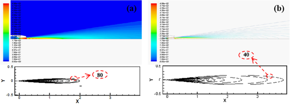
Gas velocity contour plots.
5.1.3 Estimated by the oxygen mass fraction value
It is known from numerical simulation that the oxygen mass fraction of the type G301-7# cutting nozzle at the length of the cutting oxygen jet (182 mm from the nozzle outlet) is 0.3455, and that at the cutting thickness of 300 mm is 0.292. Fig. 22(a-b) shows a contour plot of the oxygen mass fraction value on the axis of the design nozzle. It is estimated that the length of the cutting oxygen flow from the design nozzle can reach 1600 mm based on the oxygen mass fraction of 0.3455 at the axis in Fig. 22(a) and that the cutting thickness with the design nozzle can reach 2800 mm based on the oxygen mass fraction value of 0.292 at the axis in Fig. 22(b).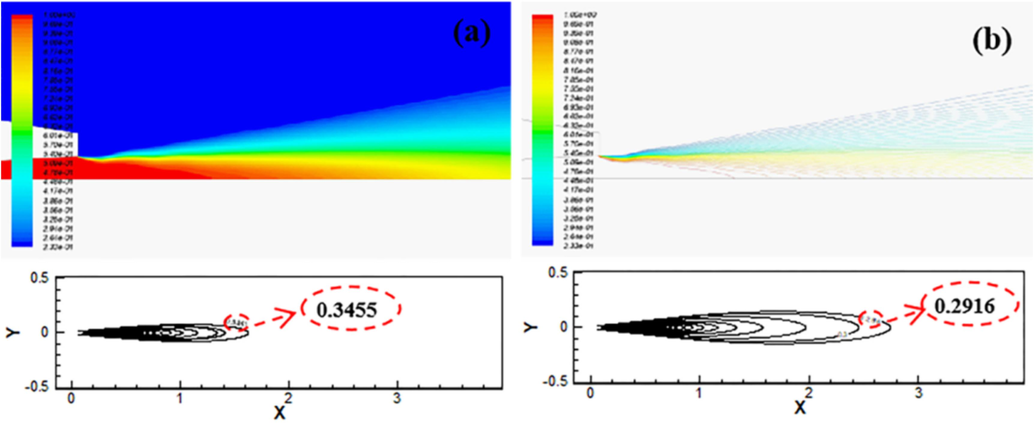
Oxygen mass fraction contour plots.
5.1.4 Estimated result analysis and test verification
By analyzing the flow field characteristics of the above designed ultrathick flame cutting nozzle and comparing the corresponding parameter values for straight orifice channel nozzles cutting a thickness of 300 mm. At a distance of 2500 mm from the outlet of the design nozzle, the values of density, velocity and oxygen mass fraction of the jet are all higher than the corresponding values at the nominal cutting thickness (300 mm) of the type G301-7# cutting nozzle. Therefore, the preliminary estimate of the cutting thickness of the design nozzle is more than 2500 mm.
Based on the predicted results, the premixed orifice channel of type G301-7# cutting nozzle is proportionally enlarged, and the channel is corrected to the flow and pressure values of oxygen and propane needed for cutting 2500 mm mild steel. The cutting oxygen orifice channel is changed to the design Laval nozzle type (throat diameter is 19 mm) of this paper. The finished cutting nozzle was manufactured as shown in Fig. 23.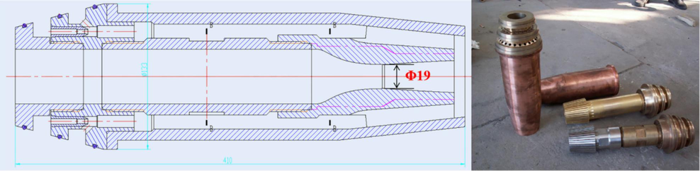
Internal mixed-flame cutting nozzle for ultra-large section steel ingot.
Fig. 24(a-b) shows a flame cutting tests on ultrathick steel ingots were carried out with this nozzle to verify its performance. Table 3 shows the cutting process parameters and cutting quality for the designed nozzle. Table 4 and Fig. 24(c-e) show that at 7 atm pressure, the large-thickness flame cutting nozzle designed in this paper can cut thicknesses up to 2500 mm, and the results agree with the cutting thickness predicted by the numerical simulation. The measurements show that the width of the upper kerf is approximately 60 mm, the width of the lower kerf is approximately 180 mm, the maximum perpendicularity is approximately 19.35 mm/m, the maximum depth of the cutting striation is 6 mm, and the flatness of the cutting surface is approximately 94.4 mm. From the test results, the quality of the cutting surface is good, but the deviation of the upper and lower width of the kerf is large. The bottom of the cutting seam exhibits serious slag hanging, which indicates that the slag removal capacity of the cutting oxygen jet at this thickness is reduced and can be optimized by increasing the inlet oxygen pressure, further improving the shape of the cutting oxygen nozzle channel and machining accuracy. With an average cutting speed of 28.5 mm/min, the working time for cutting the steel ingots of φ2500 mm diameter is approximately 88 min, which is approximately 82 % higher than the machining efficiency of machining.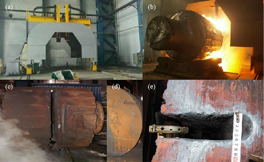
Flame cutting test of ultra-large section steel ingot.
Diameter of Ingots
/mm
Set Pressure
/MPa
Flow Rate
/m3/h
Cutting Speed
/mm/min
Preheated Oxygen
Cutting Oxygen
Propane Gas
Preheated Oxygen
Cutting Oxygen
Propane Gas
2500
0.1
0.7
0.2–0.35
270–330
700–800
90–110
17–40
Width of Kerf
/mm
Perpendicul-arity
/mm/m
Maximum Depth of the Cutting Striation(h)
/mm
Cutting Surface Flatness(u)
/mm
Upper Kerf
Middle Kerf
Lower Kerf
60
80
180
19.35
6
94.4
6 Conclusion
To enhance the performance of the cutting oxygen jet, specifically its flow rate and jet length, a mathematical model was developed for the cutting oxygen orifice of a double-arc profile Laval-type nozzle. The reliability and precision of this numerical model were validated through numerical simulation analysis and experimental research on the G301-7# cutting nozzle. This validation serves as a theoretical foundation for the design and research of supersonic flame cutting nozzles.
Based on the flow characteristics of the supersonic nozzle jet, we propose a method for estimating the structural dimensions of cutting oxygen holes in ultra-large thickness nozzles. Numerical simulations and predictive analyses were conducted on a nozzle designed having a throat diameter of 19 mm. The results indicated that the cutting oxygen jet achieves supersonic speed at the outlet and alternates between shock and expansion waves in the air until the jet velocity and pressure become adapted for the environment. Using the density value, velocity value, and mass fraction of oxygen along the axis, the maximum cutting thickness of the designed nozzle is predicted to be approximately 2,500 mm.
A cutting experiment was conducted on a supersonic nozzle designed using the prediction method to cut a support roll and ingot of YB-70 material, each 2500 mm in diameter. The results indicate that the width of the upper kerf is approximately 60 mm, while the lower kerf measures approximately 180 mm. The maximum straightness is approximately 19.35 mm/m, the maximum depth of the cutting veins is 6 mm, and the flatness of the cutting surface is approximately 94.4 mm. The reliability and applicability of the design and prediction method proposed in this paper have been validated, and the present research provides useful information on the design method of large-thickness flame cutting nozzles. Further research will consider the interaction between the preheated flame's oxygen and propane, as well as the coupling of the flame with the cutting oxygen jet, to study the process modulation effect on the surface quality of large thickness flame cutting.
Acknowledgments
This work was funded by the National Natural Science Foundation of China (Grant No. 52374383) and National Science and Technology Major Project (Grant No. 2009ZX04003-041).
CRediT authorship contribution statement
Haonan Yu: Supervision, Writing – original draft, Writing – review & editing, Funding acquisition. Xin Liu: Data curation. Zunce Wang: Conceptualization, Supervision. Haiying Zu: Validation. Bin Xiong: Software. Jian Gao: Visualization. Chenglong Guo: Data curation. Kaixuan Wang: Formal analysis.
Declaration of Competing Interest
The authors declare that they have no known competing financial interests or personal relationships that could have appeared to influence the work reported in this paper.
References
- Kinetics of oxyfuel gas cutting of steels. J. Braz. Soc. Mech. Sci. Engin.. 2011;33:183-188.
- [Google Scholar]
- Effects of plasma arc cutting process parameters on the cutting speed optimization based on the required cut quality. CIRP J. Manuf. Sci. Technol.. 2022;38:836-843.
- [CrossRef] [Google Scholar]
- A study on prediction of the size of heat affected zone in oxy-ethylene flame cutting of steel plates. Int. J. Precision. Eng.. 2016;17:733-740.
- [Google Scholar]
- Numerical analysis of heat flow in oxy-ethylene flame cutting of steel plate. Proceed. i. Mech. Eng. Bj. Eng.. 2018;232:742-751.
- [CrossRef] [Google Scholar]
- Wear characteristics of brazed diamond saw blade in cutting 304 stainless steel. Diam. Relat. Mater.. 2022;123:108869
- [CrossRef] [Google Scholar]
- Supersonic liquefaction properties of natural gas in the Laval nozzle. Energy. 2018;159:706-715.
- [Google Scholar]
- Process modelling and simulation analysis of CNC oxy-fuel cutting process on SA516 grade 70 carbon. Steel. 2018;5(2):7818-7827.
- [CrossRef] [Google Scholar]
- Behaviours of supersonic oxygen jet with various Laval nozzle structures in steelmaking process. Canadian Metallur. Quar.. 2019;58:285-298.
- [Google Scholar]
- The influence of thermal cutting on the properties and quality of the cut surfaces toughened steel S 960ql. IOP Conference Series: Materials Science and Engineering.. 2018;400(2):022032
- [Google Scholar]
- Dynamic characteristics of supersonic turbulent free jets from four types of circular nozzles. Int. J. Nonlinear Sci. Numer. Sim.. 2021;23:1.
- [Google Scholar]
- Izzet, KARAKURT., Gokhan, AYDIN., Kerim, AYDINER., 2011. A Machinability Study of Granite Using Abrasive Waterjet Cutting Technology. Gazi University Journal of Science. 24(1), 142-151.
- Characterization of Flame Cut Heavy Steel: Modeling of Temperature History and Residual Stress Formation. Metallur. Mater. Trans. B.. 2017;48:2891-2901.
- [Google Scholar]
- Role of Steel Plate Thickness on the Residual Stress Formation and Cracking Behavior During Flame Cutting. Met. Mat. Trans.. 2019;50:4178-4192.
- [Google Scholar]
- Laser and oxygen hybrid coaxial cutting method for thick clad plates made of heterogeneous metals. Opt. Lasers Eng.. 2024;175
- [Google Scholar]
- Behaviours of supersonic oxygen jet with various Laval nozzle structures in steelmaking process. Can. Metall. Q.. 2018;58(3):285-298.
- [CrossRef] [Google Scholar]
- , E., Yazdani, S., Mobini, R., Abadi, M.H.M.E., , A., Yahyazadeh, M., Tabar, M.R., 2022. Investigation of the effect of water droplet injection on condensation flow of different nozzles geometry. Euro. Phys. J. Plus. 173.
- Lectures in Mathematical Model of Turbulence. London: Academic Press; 1972.
- Simulation of Gas Flow Field in Laval Nozzle and Straight Nozzle for Powder Metallurgy and Spray Forming. J. Iron. Steel Res. Inter.. 2008;15:44-47.
- [Google Scholar]
- Characteristics of flow field for supersonic oxygen multijets with various Laval nozzle structures. Metall. Mater. Trans. B. 2019;50(5):2362.
- [Google Scholar]
- Laser cutting of aluminium-alumina metal matrix composite. Opt. Laser Technol.. 2019;117:251-259.
- [CrossRef] [Google Scholar]
- Spatially resolved ion density measurements in an oxyfuel cutting flame. Combust. Sci. Technol.. 2022;194(5):930-945.
- [CrossRef] [Google Scholar]
- Miller SW. 1916. Oxy-acetylene welding: a comprehensive treatise on the practice of welding cast iron, malleable iron, steel, copper, brass, bronze, and aluminum by the oxy-acetylene methods, together with concise information on the equipment required for both welding and cutting by this process. Industrial Press.
- Impact of Laval nozzle structure on the flow characteristics of supersonic gas-solid two-phase flow. Powder Technol.. 2024;439:119657
- [CrossRef] [Google Scholar]
- Evaluation of microstructure and mechanical properties of 50Cr5NiMoV steel for forged backup roll. Mater. Sci. Engineer. A.. 2016;667:465-473.
- [Google Scholar]
- Simulation and validation of the gas flow in close-coupled gas atomisation process: Influence of the inlet gas pressure and the throat width of the supersonic gas nozzle. Powder Tech.. 2022;407:117688
- [Google Scholar]
- Impact of Laval nozzle structure on the flow characteristics of supersonic gas-solid two-phase flow. Powder Technol.. 2024;439
- [Google Scholar]
- Evaluation and optimal design of supersonic nozzle for laser-assisted oxygen cutting of thick steel sections. Inter. J. Advan. Manuf. Tech.. 2016;86:1243-1251.
- [Google Scholar]
- Coupled modeling and numerical simulation of gas flows laden with solid particles in de Laval nozzles. Shock Waves. 2022;32:213-230.
- [Google Scholar]
- Numerical study on the shock vector control performance in a de Laval nozzle with single or dual injection ports. J. Mech. Sci. Tech.. 2022;36:3001-3016.
- [Google Scholar]
Appendix A
Supplementary data
Supplementary data to this article can be found online at https://doi.org/10.1016/j.arabjc.2024.105894.
Appendix A
Supplementary data
The following are the Supplementary data to this article:Supplementary video 1
Supplementary video 1
Supplementary video 2
Supplementary video 2
Supplementary video 3
Supplementary video 3
Supplementary video 4
Supplementary video 4
Supplementary video 5
Supplementary video 5


