Translate this page into:
Design highly effective B or N doped mesoporous carbon fibers catalysts for I3-/I- redox couple regeneration in carbon-based dye-sensitized solar cells
⁎Corresponding author. mingxing.wu@hebtu.edu.cn (Mingxing Wu)
-
Received: ,
Accepted: ,
This article was originally published by Elsevier and was migrated to Scientific Scholar after the change of Publisher.
Abstract
Construction of mesoporous structure and improving the conductivity of carbon counter electrode are feasible paths to enhance the catalytic activity in dye-sensitized solar cells (DSCs) toward the I3-/I- redox couple regenerating (IRR). Herein, mesoporous carbon fiber (PCf) has been first synthesized and the DSCs using PCf counter electrode results in a power conversion efficiency (PCE) of 7.12%, significantly surpassing the PCE of 6.01% generated by the DSCs with carbon fiber (Cf) counter electrode without mesoporous structure. Additionally, doping with heteroatoms B or N can further enhance the catalytic performance of PCf. Consequently, B or N doped Cf (BPCf or NPCf) counter electrode-based DSCs achieve high PCE values of 8.43% and 7.96%, respectively, demonstrating PCE improvements of 40.3% and 32.4%. This enhancement in catalytic activity for IRR in DSCs can be first attributed to the increased specific surface area of Cf which can provide more catalytic activated sites. Meanwhile, the enhanced conductivity of PCf by heteroatoms B or N doping is also an important factor for the improved catalytic activity. This work is expected to provide potential path to enhanced the catalytic activity of carbon counter electrode in DSCs toward IRR.
Keywords
Counter electrode
IRR
Dye-sensitized solar cells
Porous
Doping
1 Introduction
Developing low-cost and highly effective counter electrode catalysts for the I3-/I- redox couple regenerating (IRR) remains a significant research focus within the dye-sensitized solar cells (DSCs) domain, due to the inherent disadvantages of Pt counter electrodes, such as high cost and susceptibility to corrosion by the iodide redox couple (Wu et al., 2017; Yun et al., 2018). Through persistent scientific exploration, a variety of economical counter electrode catalysts have been proposed, including carbon materials, organic polymers, transition metal compounds, alloys, perovskite oxides, spinel materials, and composites (Ding et al., 2023; Chai et al., 2023; Lu et al., 2019; Gao et al., 2018; Duan et al., 2014; Cui et al., 2021; Bezabin, 2023). Among these, carbon materials exhibit considerable potential for practical application, attributed to their widespread availability, high catalytic activity, and exceptional stability (Wu et al., 2020). Notably, carbon black was proposed as a counter electrode catalyst for IRR of DSCs as early as 1996, achieving a PCE of 6.67 % (Kay and Grätzel, 1996). Subsequently, a diverse array of carbon materials has been explored for use in DSCs, such as activated carbon, graphite, carbon nanotubes, graphene, carbon molecular sieve, porous carbon, carbon spheres, carbon nano cubes, and carbon nano horns (Imoto et al., 2003; Li et al., 2015; Chen et al., 2016; Kavan et al., 2011; Li et al., 2016; Chen et al., 2013; Wu et al., 2015; Jian et al., 2018; Lodermeyer et al., 2016). Comprehensive insights into carbon counter electrode materials are provided in a review paper (Wu et al., 2020). Carbon fiber (Cf), a classic one-dimensional material with diameters ranging from several nanometers to several micrometers, which stands out among various carbon materials by high temperature resistance, friction resistance, thermal and electrical conductivity, and corrosion resistance, owing to its graphite microcrystalline structure with preferred orientation along the fiber axis. Therefore, Cf has been extensively utilized in electrochemistry (Inagaki et al., 2012; Mamun et al., 2023).
In 2010, Cf was introduced as a low-cost candidate to Pt counter electrodes for IRR of DSCs, achieving a PCE of 5.5 % (Joshi et al., 2010). Despite this innovation, the PCE of DSCs with Cf counter electrodes remained lower than those using Pt-based counterparts. Baglio et. al synthesized Cf through decomposition of methane at varying temperatures, controlling the average diameter of Cf between 24 nm and 63 nm (Sebastián et al., 2014). After optimization, the DSCs equipped with Cf counter electrodes demonstrated a PCE of 2.17 %. It was discovered that the catalytic activity of Cf is predominantly influenced by its surface area and the degree of surface graphitization, which vary with sintering temperatures. A significant improvement was achieved by the development of helical carbon nanofibers (HCNF), prepared via the pyrolysis of acetylene, which enabled corresponding DSCs to reach a PCE of 6.74 %, nearly matching that of DSCs using Pt counter electrode (Wang et al., 2016). Although the interconnected fabric structure of HCNF facilitates mass transport and charge transfer in IRR progress, further enhancement in catalytic activity is necessary. To address this, the incorporation of super catalysts into Cf to create composite counter electrodes has emerged as a viable strategy for enhancing catalytic activity. Our team prepared Pt/Cf composite counter electrodes for three different redox couples (Co3+/2+, T2/T-, and I3-/I-) in DSCs (Guo et al., 2015). With 1.0 wt% Pt loading, the Pt/Cf composite counter electrode exhibited high catalytic activity, resulting in DSCs with PCEs of 7.88 % (I3-/I-), 5.85 % (T2/T-), and 9.41 % (Co3+/2+). Additionally, the Qiao group developed carbon nanofibers with surface-attached Pt nanoparticles (ECNFs-PtNPs) as counter electrodes, achieving a PCE of 7.6 % (Aboagye et al., 2015). Furthermore, composites such as MoS₂/Cf, VO₂/Cf, Ni/Cf, MoO₂/Cf, Pt3Ni/Cf, Co3S₄/Cf, NiCo₂S₄/Cf, PANI/CNTF, Ni–Co–Se/Cf, and CoP@Ni₂P/Cf have also been utilized as Cf composite counter electrodes in DSCs (Chi et al., 2017; Choudhury et al., 2021; Du et al., 2022; Gnanasekar et al., 2019; Hendi et al., 2024; Li et al., 2016, 2017, 2018; Zhou et al., 2016). Recognizing the strategy of construction of porous structures to enhance catalytic activity is scarcely reported, we herein synthesized mesoporous carbon fiber (PCf) via electrospinning method, demonstrating superior catalytic activity for IRR as compared to the pristine Cf. Moreover, nitrogen or boron-doped PCf (NPCf, BPCf) were synthesized to further enhance catalytic activity. Consequently, the DSCs employing PCf, NPCf, and BPCf counter electrodes achieved PCE values of 7.12 %, 7.96 %, and 8.43 %, significantly outperforming that with pristine Cf counter electrode (6.01 %). The enhanced catalytic activities for IRR were validated through electrochemical analysis methods, including electrochemical impedance spectroscopy (EIS), cyclic voltammetry (CV), and Tafel polarization curves.
2 Experimental section
Key materials: Polyacrylonitrile (PAN, Mw = 80,000) was purchased from Energy Chemical (Shanghai, China), N719 dye (Greatcell solar), TiO2 paste (18NR-T), LiI, guanidinium thiocyanate, I2, 4-tert-butylpyridine (TBP), N, N-dimethylformamide (DMF, ≥ 99.9 %) and potassium hydroxide (KOH, 95 %) were purchased from Aladdin Biochemical Technology Co. Ltd (Shanghai China).
The materials synthesis, device fabrication details and Characterization methods are summarized in the Supporting Information
3 Results and discussion
Scanning electron microscopy (SEM) was initially utilized to examine the surface morphologies of Cf, which was synthesized through the electrospinning process. The SEM image (Fig. S1) reveals that the PAN precursor exhibits smooth and monofilament profile with diameters ranging from 150 nm to 200 nm. Following preoxidation and carbonization, the resultant Cf maintained its fibrous structure, albeit with some degree of bending (Fig. 1a). Subsequent incorporation of a pore-forming agent, SiO2 aerogel, cannot alter the slender shape of the PAN precursors, which has diameters between 100 nm and 250 nm, as shown in Figs. S2-S4.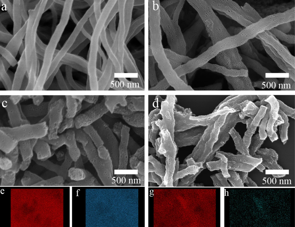
SEM images of the prepared Cf (a), PCf (b), BPCf (c) and NPCf (d); Elemental mapping images of C (e) and B (f) in BPCf, C (g) and N (h) in NPCf.
Unlike the pristine Cf, the synthesized mesoporous carbon fibers (PCf, BPCf, and NPCf) feature intensive, uniformly distributed mesopores within each fiber (Fig. 1b-1d). The distorted fibers in PCf, BPCf, and NPCf are intertwined, adhering to one another to create a crisscrossed network structure. This configuration is conducive to providing an extensive surface area and efficient mass transport channels for the redox couple. It is also observed that the fibers in PCf, BPCf, and NPCf appear fragmented and shorter, likely due to the addition and subsequent removal of the pore-forming agent or heteroatom sources. The elemental mapping images (Fig. 1e-1 h) confirm the uniform dispersion of heteroatoms B and N within the synthesized BPCf and NPCf.
Transmission electron microscopy (TEM) images in Fig. 2 corroborate that the four types of carbon fibers maintain a distinct fibrous shape. While the pristine Cf displayed a solid structure devoid of mesopores, clear mesopores can be identifiable in PCf, BPCf, and NPCf. In the X-ray diffraction (XRD) patterns (Fig. S5), a pronounced diffraction peak at 24.50°, referring to the crystalline plane of (0 0 2), is observed evidently, indicating the presence of a hexagonal graphite phase in the four Cf samples. The peaks with low intensity at 31.62° and 36.70° may be attributed to residual pore-forming agents that are not completely removed. In summary, the carbon fiber samples (Cf, PCf, BPCf, and NPCf) have been successfully synthesized, and the crosslinked mesoporous structure is contributed to enhanced conductivity in line with the theory of conductive circuit formation (Miyasaka et al., 1982). This structural configuration also aids in improving the catalytic activity for IRR in DSCs.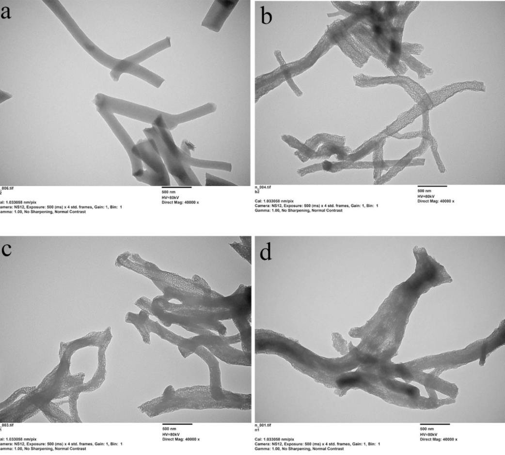
TEM images of the prepared Cf (a), PCf (b), BPCf (c) and NPCf (d).
To validate the synthesis of BPCf and NPCf, XPS analyses were performed to elucidate the interactions between carbon atoms and either boron or nitrogen atoms. Figs. S6 and S7 display the panoramic XPS spectra for BPCf and NPCf, respectively. The distinct signals for C, B, and N are clearly evident and the B and N contents are 2.30 wt% and 9.94 wt%. Typically, the B 1 s characteristic peak for pristine boron is located at 187.0 eV, whereas in BPCf, this peak shifts to a higher binding energy region (Fig. 3a) (Jacques et al., 1996; Panchakarla et al., 2007). Specifically, the B 1 s peaks exhibit an asymmetric profile, indicative of three distinct chemical environments. The peaks at 193.16 eV, 192.20 eV, and 190.86 eV correspond to the BCO₂, BC₂O, and BC3 phases, respectively (Sheng et al., 2012). The BC3 configuration arises from the substitution of carbon atoms with boron atoms in the graphite lattice, while the BC₂O and BCO₂ peaks suggest an interaction between boron atoms and the oxygen and carbon atoms, resulting in partial oxidation of boron in BPCf. These findings are confirmed by the characteristic peak shifts towards higher energy, signifying the substitution of carbon atoms with boron (Sheng et al., 2012; Lyu et al., 2011). In NPCf, the N 1 s spectrum (Fig. 3b) deconvolutes into three peaks at 398.02 eV, 400.46 eV, and 402.38 eV, attributed to pyridinic-N, pyrrolic-N, and graphitic-N, respectively, which aligns with previous research (Cheng et al., 2015). The incorporation of doped boron and nitrogen atoms not only introduces defects but also enhances the conductivity of the carbon fibers, thereby improving the electrochemical performance (Cheng et al., 2015; Jeong et al., 2011; Kim et al., 2023). As depicted in the Raman spectra of the four samples (Fig. 3c), the D-band peaks corelated to defect lattice vibration modes are found around 1342 cm-1, while the G-band peaks, representative of graphitic lattice vibration modes, are located around 1552 cm-1. The intensities of the D-band peaks for PCf, BPCf, and NPCf are marginally higher than that of the pristine Cf, which could be attributed to the variation in the disordering degree within the graphite hexagonal lattice, induced by heteroatom doping and the introduction of a mesoporous structure. Furthermore, the enhanced D-band peak intensities for PCf, BPCf, and NPCf suggest a higher degree of graphitization. The intensity ratio of the D-band to G-band peaks (ID/IG) for PCf, BPCf, and NPCf is slightly lower than that of Cf, implying that the conductivities of PCf, BPCf, and NPCf surpass that of pristine Cf. The conductivities of the four carbon fiber samples were further assessed using four-probe resistivity tests. Specifically, the square resistances of Cf, PCf, BPCf, and NPCf are 92 Ω/sq, 75 Ω/sq, 62 Ω/sq, and 65 Ω/sq, respectively.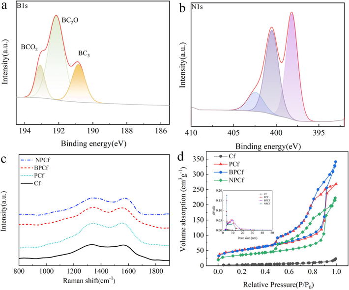
XPS spectra of (a) B 1 s in BPCf and (b) N 1 s in NPCf; (c) Raman spectra and (d) N2 adsorption–desorption isotherms of Cf, PCf, BPCf and NPCf. The inset in (d) is the pore size distribution curves.
N₂ adsorption–desorption isotherms were utilized to assess the internal structure of the four synthesized Cf samples. As illustrated in Fig. 3d, the pristine Cf exhibits a type III adsorption isotherm characterized by a concave profile without a significant B inflection point. This profile suggests a weaker interaction between N₂ and Cf compared to the interaction between N₂ molecules themselves. Moreover, the heat of liquefaction of N₂ surpasses the isosteric heat of adsorption, indicating that N₂ molecules face challenges in being adsorbed at the initial stage, which results in a reduced adsorption volume at the saturation pressure point. Consequently, the surface area of the pristine Cf, as determined by BET analysis, is limited to 12.7 m2g−1. In contrast, PCf, BPCf, and NPCf samples exhibit noticeable capillary condensation of N₂, indicative of classic type IV sorption isotherms with characteristic hysteresis loops. This confirms the successful construction of mesoporous structure in PCf, BPCf, and NPCf, evidenced perfectly by the SEM and TEM findings. The surface areas of PCf, BPCf, and NPCf are significantly enhanced to 176.8 m2g−1, 176.2 m2g−1, and 119.4 m2g−1, respectively, compared to pristine Cf. Moreover, the total pore volumes for PCf, BPCf, and NPCf are substantially higher, recorded at 0.44 cm3g−1, 0.56 cm3g−1, and 0.38 cm3g−1, respectively, in stark contrast to pristine Cf (0.032 cm3g−1). The inset in Fig. 3d is the BJH pore size distributions which reveals the pore sizes for PCf, BPCf, and NPCf are approximately 9.36 nm, 9.04 nm, and 10.25 nm, respectively, surpassing the pore size of pristine Cf, which is below 2.0 nm. In a word, the combined results of SEM, TEM, and N₂ adsorption–desorption isotherms confirm the formation of mesoporous structures in PCf, BPCf, and NPCf. The enhanced surface area and interconnected structure are crucial for the elevated catalytic activity of counter electrodes for IRR.
Fig. 4a presents the photocurrent density–voltage (J-V) curves for I3-/I- electrolyte-based DSCs equipped with counter electrodes made of pristine Cf, PCf, BPCf, and NPCf. The baseline DSCs utilizing pristine Cf counter electrodes yields PCE in the range of 5.90 % to 6.01 %, and the highest PCE of 6.01 % combined with open circuit voltage (VOC) of 0.741 V, short-circuit current density (JSC) of 14.23 mA cm-2, and fill factor (FF) of 0.57. Substituting the counter electrode catalyst with mesoporous PCf resulted in enhanced PCE of 6.99 % to 7.12 %, accompanied by the highest JSC of 14.33 mA cm-2, VOC of 0.771 V, and FF of 0.64. This improvement in PCE is primarily attributed to the increases in FF and VOC. Although PCf demonstrated enhanced catalytic activity in DSCs for the I3-/I- redox couple regeneration, further augmentation of the catalytic activity was sought. Consequently, heteroatom of B or N-doped BPCf and NPCf were introduced as counter electrode catalysts, yielding PCEs of 8.29 % to 8.43 % with the optimal JSC = 15.45 mA cm-2, VOC = 0.791 V, FF = 0.69 and 7.80 % to 7.96 % (JSC = 14.86 mA cm-2, VOC = 0.788 V, FF = 0.68), respectively. The PCE values with error bars are summarized in Fig. S8 Notably, when compared with PCf the key photovoltaic parameters of JSC, VOC, and FF for BPCf and NPCf indicate significant enhancements due to heteroatom doping. A longitudinal comparison with previous studies on DSCs utilizing Cf-based counter electrodes is provided in Table 1, summarizing PCE values ranging from 2.17 % to 9.41 %, with the highest PCE observed for the composite counter electrode of Pt/Cf in a Co3+/2+ redox system. The PCEs achieved in this study surpass most previously reported data, affirming that the design of a mesoporous structure and heteroatom doping are effective strategies to enhance the catalytic activity toward IRR.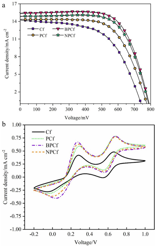
(a) Photocurrent density–voltage (J − V) curves of the DSCs using Cf, PCf, BPCf, and NPCf counter electrode; (b) Cyclic voltammograms of the four Cf electrodes in I3-/I- electrolyte.
Counter electrode
Redox couple
PCE
Ref
Cf
I3−/I−
5.5 %
23
Cf
I3−/I−
2.17 %
24
HCNF
I3−/I−
6.74 %
25
Pt/Cf
I3−/I−
7.88 %
26
Pt/Cf
T2/T−
5.85
26
Pt/Cf
Co3+/2+
9.41 %
26
ECNFs-PtNPs
I3−/I−
7.6 %
27
Ni/Cf
I3−/I−
7.14
28
VO2/Cf
I3−/I−
6.53 %
29
Pt3Ni/Cf
I3−/I−
9.17 %
30
MoS2/Cf
I3−/I−
8.46 %
31
MnO2/Cf
I3−/I−
8.86 %
32
NiCo2S4/Cf
I3−/I−
6.31 %
33
PANI/CNTF
I3−/I−
3.69 %
34
Ni–Co–Se/Cf
I3−/I−
2.03 %
35
CoP@Ni2P/Cf
I3−/I−
8.33 %
36
Cf
I3−/I−
6.06 %
This work
PCf
I3−/I−
7.17 %
This work
BPCf
I3−/I−
8.38 %
This work
NPCf
I3−/I−
7.99 %
This work
To elucidate the effect of mesoporous structure and heteroatom doping on enhancing catalytic activity, cyclic voltammetry (CV) measurements were performed using the prepared carbon fibers (Cf, PCf, BPCf, and NPCf) as working electrodes in I3-/I- electrolyte to assess their electrochemical properties. In Fig. 4b, the cyclic voltammograms of the four Cf counter electrodes exhibit two pairs of redox peaks. One pair, located at a negative potential, is associated with the redox reaction of I3-/I-, and the other, at a positive potential, corresponds to the redox reaction of I₂/I3- (Zhu et al., 2017). The redox reaction of I3-/I-, being crucial in the IRR process, allows the evaluation of catalytic performance through analyzing the electrochemical parameters such as current density, reduction peak potential, and peak separation (ΔEp) for the redox peaks at negative potential (Guo et al., 2016). For the pristine Cf counter electrode, the reduction peak potential is at −0.053 V, with a ΔEp of 0.332 V. With the introduction of mesopores, the reduction peak potential shifts to more positive potential of −0.040 V, indicating a lower overpotential for IRR, thereby facilitating easier redox couple regeneration on PCf compared to Cf. Furthermore, the reduction peak potentials for BPCf and NPCf are at −0.003 V and 0.049 V, respectively, suggesting further reduced overpotentials. The ΔEp values for BPCf and NPCf are 0.218 V and 0.276 V, respectively, implying more reversible redox reaction of I3-/I- on the two modified counter electrodes compared to Cf. Additionally, a narrow ΔEp signifies a higher charge transfer rate (ks), positioning BPCf as the most effective counter electrode catalyst, followed by NPCf, PCf, and Cf. The increased reduction peak current densities for BPCf, NPCf, and PCf, in comparison to pristine Cf, further demonstrate the accelerated redox reaction on the three optimized Cf counter electrodes. In a word, CV results verify that the catalytic activity of Cf counter electrodes has been significantly enhanced by incorporating a mesoporous structure and heteroatom doping.
EIS serves as a crucial tool for evaluating the catalytic performance of counter electrode through examining key kinetic parameters. Fig. 5a displays the Nyquist plots of symmetrical dummy cells, where the intersection on the real axis can be considered as the series resistance (Rs). The left semicircle denotes the charge transfer resistance (Rct) along with the double-layer capacitance (Cμ), and the right semicircle indicates the diffusion impedance (Z). The key EIS parameters can be derived based on the equivalent circuit model (Fig. S9), with Rct connected in series to Z, and both in parallel to the Cμ (Aftabuzzaman et al., 2020). The Rs for the pristine Cf is 21.2 Ω, which decreases to 19.3 Ω for PCf due to the introduction of mesopores, and further decreases to 16.6 Ω and 17.1 Ω for BPCf and NPCf, respectively, caused by boron and nitrogen doping. This reduction in Rs is partially due to the enhanced conductivity of the Cf electrode as four-probe resistivity tests proved. Moreover, the Rct values decline from 22.4 Ω for Cf to 17.4 Ω for PCf, 14.2 Ω for BPCf, and 15.9 Ω for NPCf, indicating an accelerated reaction rate and lower resistance for the I3-/I- redox couple on the BPCf, NPCf, and PCf counter electrodes. The decrease in Rct is attributed to the augmented intrinsic catalytic activity and the expansion of catalytic active sites provided by the mesoporous structure and heteroatom doping. Additionally, the mesoporous structure provides more efficient diffusion pathways for the I3-/I- redox couple, resulting in significantly lower Z values for BPCf (20.4 Ω), NPCf (23.2 Ω), and PCf (27.5 Ω) compared to Cf (39.5 Ω). Besides, Tafel polarization curves were utilized to determine two crucial electrochemical parameters: the exchange current density (J0) and the limiting diffusion current density (Jlim). The Tafel polarization curves depicted in Fig. 5b exhibit three distinct regions: the Tafel region characterized by a steep slope at moderate potential, the polarization region below 120 mV, and the horizontal diffusion region at high potential. Within the Tafel region, an increase in J0 values is noted in the sequence of Cf, PCf, NPCf, and BPCf. This variation in J0 suggests a decrease in Rct values, attributed to the introduction of a mesoporous structure and doping of N and B. According to Eq. (1), this trend in Rct values aligns well with the results obtained from EIS, indicating a consistent enhancement in catalytic activity due to the mesoporous structure and heteroatom doping.
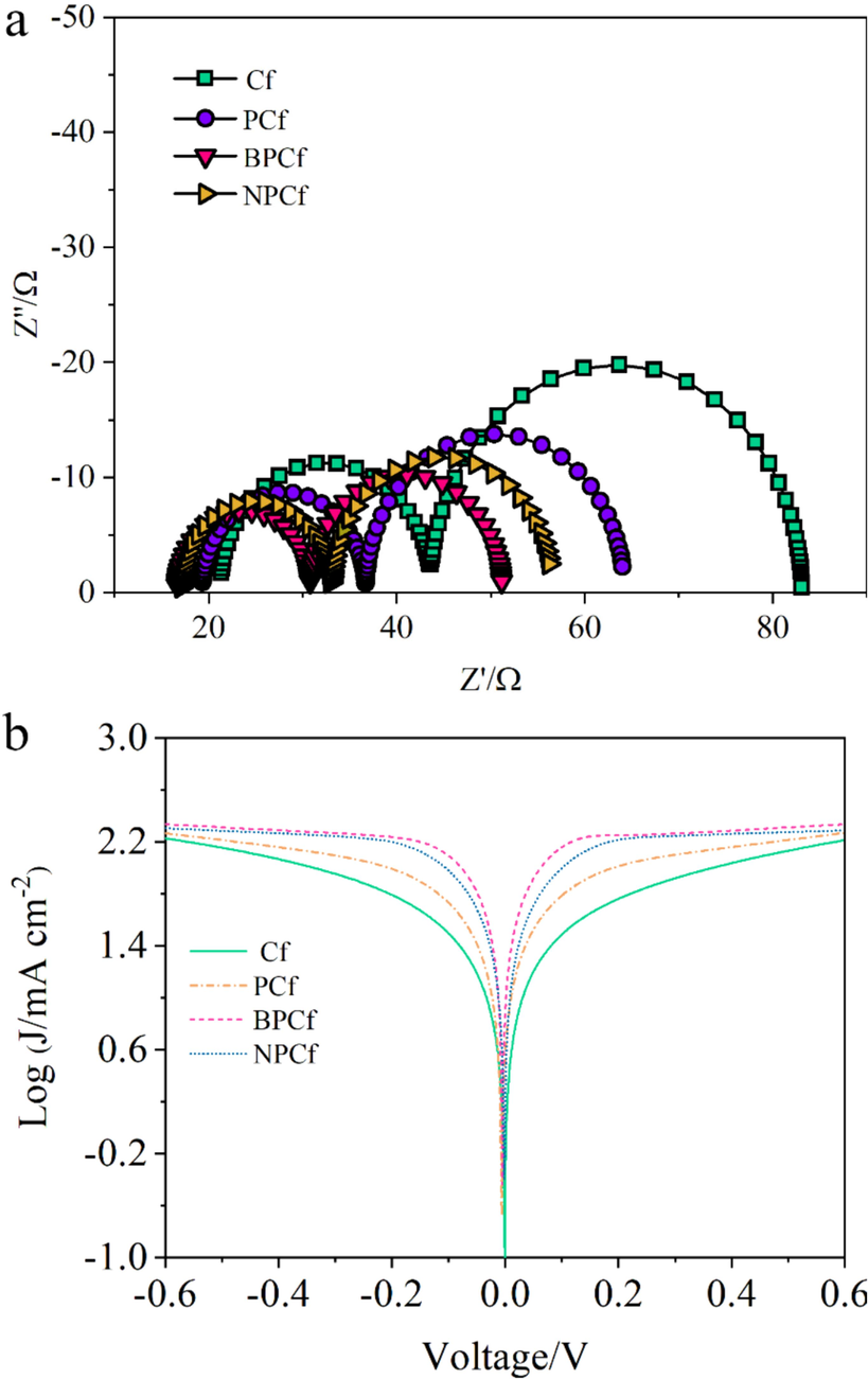
(a) Nyquist plots and (b) Tafel polarization curves of the symmetrical cells fabricated with two identical Cf electrodes.
In the diffusion region, the synthesized BPCf, NPCf, and PCf presented large Jlim than the pristine Cf, indicating better mass transport properties of BPCf, NPCf, and PCf caused by the introduced mesopores. Moreover, The Z values can be also achieved using the ionic diffusion coefficient (D) according to Eq. (2), in which D can be deduced based on Eq. (3). Taking overall consideration of both Eq. (2) and Eq. (3), Z is inversely proportional to . We can deduce that Z values following the order of BPCf < NPCf < PCf < Cf, which is in conformity with the EIS results.
The CV, EIS, and Tafel polarization results proved that Cf is a potential counter electrode toward iodide redox couple in DSCs. Although the synthesized BPCf and NPCf showed high catalytic activity which is still lower than Pt, and the DSCs using Pt counter electrode showed a PCE of 8.57 % (Fig. S10). The authors consider that develop metal atom doped carbon fiber composite counter electrode is a potential path to further enhance the IRR catalytic activity and the application field of Cf can be extended to other redox couple or other types of photovoltaic, such as Co3+/2+, quantum dot and hybrid photovoltaics (Lin et al., 2021; Liu et al., 2022; Li et al., 2023).
Finally, the long-term stability of the device is a feasible path to examine the preliminary stability of the counter electrode catalysts. However, our laboratory lacks packaging equipment, the stability test is replaced by successive CV scanning measurements which can eliminate the influence of photoanode according to previous reports (Lin et al., 2024; Xin et al., 2024; Wang et al., 2023) Fig. 6 is the successive cyclic voltammograms of four Cf electrodes in iodide electrolyte. After 25 cycles, the location of the reduction peak cannot be observed to shift. Moreover, no significant attenuation of current density can be found. The successive CV measurements prove that the for Cf counter electrodes own good electrochemical reversibility and stability in iodide electrolyte.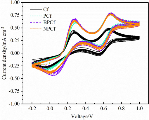
Successive Cyclic voltammograms of the four Cf electrodes in I3-/I- electrolyte.
4 Conclusion
In summary, Cf was proved to be a potential counter electrode catalyst for the I3-/I- redox couple regeneration in DSCs which generated a PCE of 6.01 %. Moreover, the constructed mesopore structure of PCf can facilitate diffusion process as well as provide more catalytic active sites for IRR and the DSCs incorporating PCf counter electrode achieved a PCE of 7.12 % with increased Jsc, Voc and FF. It’ s found that the catalytic activity of PCf can be further enhanced by doping with heteroatoms B or N and the DSCs exhibited higher PCEs of 8.43 % (BPCf) and 7.96 % (NPCf), respectively, implying PCE enhancements of 40.3 % and 32.4 % as compared with the counterpart using the pristine Cf counter electrode. The CV, EIS, and Tafel polarization measurements also proved that mesopore structure and heteroatoms can promote the mass transport and charge transfer processes effectively. Moreover, the four Cf electrode showed high stability in iodide electrolyte. This study provides a viable strategy for developing efficient and cost-effective carbon counter electrode catalysts for IRR in DSCs.
CRediT authorship contribution statement
Jie Lian: Formal analysis, Methodology, Writing – original draft. Wenyu Gong: Methodology. Jianing Guo: Funding acquisition. Mingxing Wu: Conceptualization, Supervision, Validation, Writing – review & editing.
Acknowledgements
This work was financially supported by Natural Science Foundation of Hebei Province (B2021205029), National Natural Science Foundation of China (22109039), the Central Guidance on Local Science and Technology Development Fund of Hebei Province (226Z4301G), Top-Level Talent Support Plan of Hebei Province (IV), and the Innovation Capability Improvement Plan Project of Hebei Province (22567604H).
References
- Electrospun carbon nanofibers with surface-attached platinum nanoparticles as cost-effective and efficient counter electrode for dye-sensitized solar cells. Nano Energy. 2015;11:550-556.
- [CrossRef] [Google Scholar]
- Recent progress on nanostructured carbon based counter/back electrodes for high–performance dye–sensitized and perovskite solar cells. Nanoscale. 2020;12:17590-17648.
- [CrossRef] [Google Scholar]
- Nanocomposite Counter-Electrode Materials for Dye-Sensitized Solar Cells: A Review. Energy Technol. 2023;12:2300709
- [CrossRef] [Google Scholar]
- Biomass-derived carbon for dye-sensitized solar cells: a review. J. Mater. Sci.. 2023;58:6057-6075.
- [CrossRef] [Google Scholar]
- Ultrafast synthesis of carbon-nanotube counter electrodes for dye-sensitized solar cells using an atmospheric-pressure plasma jet. Carbon. 2016;98:34-40.
- [CrossRef] [Google Scholar]
- Three-dimensional ordered macroporous carbon as counter electrodes in dye-sensitized solar cells. Thin Solid Films. 2013;539:122-126.
- [CrossRef] [Google Scholar]
- Flexible and cross-linked N-doped carbon nanofiber network for high performance freestanding supercapacitor electrode. Nano Energy. 2015;15:66-74.
- [CrossRef] [Google Scholar]
- NiCo2S4 nanosheets in situ grown on carbon fibers as an efficient counter electrode for fiber-shaped dye-sensitized solar cells. J. Mater. Sci. Mater. Electron.. 2017;28:10640-10644.
- [CrossRef] [Google Scholar]
- Carbon Fibers Coated with Ternary Ni–Co–Se Alloy Particles as a Low-Cost counter electrode for flexible dye sensitized solar cells. ACS Appl. Energy Mater.. 2021;4:870-878.
- [CrossRef] [Google Scholar]
- Surface active-site engineering in hierarchical PtNi nanocatalysts for efficient triiodide reduction reaction. NanoResearch. 2021;14:4714-4718.
- [Google Scholar]
- An overview of the preparation and application of counter electrodes for DSSCs. RSC Adv.. 2023;13:12309-12319.
- [CrossRef] [Google Scholar]
- CoP@Ni2P microcrystals in situ grown on carbon fiber as counter electrode catalysts for high-efficiency dye-sensitized solar cells. Materials Today Sustainability.. 2022;20:100262
- [CrossRef] [Google Scholar]
- Transparent Metal Selenide Alloy Counter Electrodes for High-Efficiency Bifacial Dye-Sensitized Solar Cells. Angew. Chem. Int. Ed.. 2014;53:14569-14574.
- [CrossRef] [Google Scholar]
- Review on transition metal compounds based counter electrode for dye-sensitized solar cells. J. Energy Chem.. 2018;27:703-712.
- [CrossRef] [Google Scholar]
- Pt-free, low-cost and efficient counter electrode with carbon wrapped VO2(M) nanofiber for dye-sensitized solar cells. Sci. Rep.. 2019;9:5177.
- [CrossRef] [Google Scholar]
- Synthesis of highly effective Pt/Carbon fiber composite counter electrode catalyst for Dye-Sensitized solar cells. Electrochim. Acta. 2015;176:997-1000.
- [CrossRef] [Google Scholar]
- A general approach towards carbon supported metal carbide composites for cobalt redox couple based dye-sensitized solar cells as counter electrodes. J. Power Sources. 2016;332:399-405.
- [CrossRef] [Google Scholar]
- Electrodeposited polyaniline based carbon nanotubes fiber as efficient counter electrode in wire-shaped dye sensitized solar cells. Nanotechnology. 2024;35:085704
- [CrossRef] [Google Scholar]
- High-performance carbon counter electrode for dye-sensitized solar cells. Sol. Energy Mater. Sol. Cells. 2003;79:459-469.
- [CrossRef] [Google Scholar]
- Carbon nanofibers prepared via electrospinning. Adv. Mater.. 2012;24:2547-2566.
- [CrossRef] [Google Scholar]
- LPCVD and characterization of boron-containing pyrocarbon materials. Carbon. 1996;34:1135-1143.
- [CrossRef] [Google Scholar]
- Nitrogen-Doped Graphene for High-Performance Ultracapacitors and the Importance of Nitrogen-Doped Sites at Basal Planes. Nano Lett.. 2011;11:2472-2477.
- [CrossRef] [Google Scholar]
- A zeolitic imidazolate framework-derived ZnSe/N-doped carbon cube hybrid electrocatalyst as the counter electrode for dye-sensitized solar cells. J. Mater. Chem. A. 2018;6:5107-5118.
- [CrossRef] [Google Scholar]
- Electrospun Carbon Nanofibers as Low-Cost Counter electrode for Dye-Sensitized solar cells. ACS Appl. Mater. Interfaces. 2010;2:3572-3577.
- [CrossRef] [Google Scholar]
- Optically transparent cathode for dye-sensitized solar cells based on graphene nanoplatelets. ACS Nano. 2011;5:165-172.
- [CrossRef] [Google Scholar]
- Low cost photovoltaic modules based on dye sensitized nanocrystalline titanium dioxide and carbon powder. Sol. Energy Mater Sol. Cells. 1996;44:99-117.
- [CrossRef] [Google Scholar]
- Enhancing thermoelectric performance in carbon fiber-reinforced cement composites through boron doping. Constr Build Mater.. 2023;392:131983
- [CrossRef] [Google Scholar]
- A comparative evaluation of catalytic activities of carbon molecular sieve counter electrode toward different redox couples in dye-sensitized solar cells. Electrochim. Acta. 2016;200:168-173.
- [CrossRef] [Google Scholar]
- Graphite with Different Structures as Catalysts for Counter Electrodes in Dye-sensitized Solar Cells. Electrochim. Acta. 2015;179:211-219.
- [CrossRef] [Google Scholar]
- Molybdenum-doped Pt3Ni on carbon nanofibers as counter electrode for high-performance dye-sensitized solar cell. Electrochim. Acta.. 2016;219:350-355.
- [CrossRef] [Google Scholar]
- Synthesis of highly effective MnO2 coated carbon nanofibers composites as low cost counter electrode for efficient dye-sensitized solar cells. J. Power Sources. 2017;363:9-15.
- [CrossRef] [Google Scholar]
- Electrospinning synthesis of high performance carbon nanofiber coated flower-like MoS2 nanosheets for dye-sensitized solar cells counter electrode. Electrochim. Acta. 2018;280:94.
- [CrossRef] [Google Scholar]
- Fe Single Atom Catalysts Promoting Polysulfide Redox Reduction in Quantum Dot Photovoltaics. Nano Lett.. 2023;23:5123-5130.
- [CrossRef] [Google Scholar]
- Graphene-Supported Small-Sized FeSe2 Nanoparticles As Efficient Counter Electrode Catalysts for Dye-Sensitized Solar Cells. Energy Fuels. 2024;38:5475-5484.
- [CrossRef] [Google Scholar]
- Nickel-Based Single-Atom Catalyst toward Triiodide Reduction Reaction in Hybrid Photovoltaics. ACS Sustainable Chem. Eng.. 2021;9:4256-4261.
- [CrossRef] [Google Scholar]
- Molybdenum-Single Atom Catalyst for High-Efficiency Cobalt(III)/(II)-Mediated Hybrid Photovoltaics. ACS Appl. Energy Mater.. 2022;5:12991-12998.
- [CrossRef] [Google Scholar]
- Facile and quick preparation of carbon nanohorn-based counter electrodes for efficient dye-sensitized solar cells. Nanoscale. 2016;8:7556-7561.
- [CrossRef] [Google Scholar]
- Porous N-doped-carbon coated CoSe2 anchored on carbon cloth as 3D photocathode for dye-sensitized solar cell with efficiency and stability outperforming Pt. Nano Res.. 2019;12:159-163.
- [Google Scholar]
- Synthesis of boron-doped double-walled carbon nanotubes by the catalytic decomposition of tetrahydrofuran and triisopropyl borate. Carbon. 2011;49:1532-1541.
- [CrossRef] [Google Scholar]
- A recent review of electrospun porous carbon Nanofiber Mats for energy storage and generation applications. Membranes. 2023;13:830.
- [CrossRef] [Google Scholar]
- Electrical conductivity of carbon-polymer composites as a function of carbon content. J. Mater. Sci.. 1982;17:1610-1616.
- [CrossRef] [Google Scholar]
- Nitrogen-and boron doped double walled carbon nanotubes. ACS Nano. 2007;1:494-500.
- [CrossRef] [Google Scholar]
- Carbon nanofiber-based counter electrodes for low cost dye-sensitized solar cells. J. Power Sources. 2014;250:242-249.
- [CrossRef] [Google Scholar]
- Synthesis of boron doped graphene for oxygen reduction reaction in fuel cells. J. Mater. Chem.. 2012;22:390-395.
- [CrossRef] [Google Scholar]
- Helical carbon nanofiber as a low-cost counter electrode for dye-sensitized solar cells. Mater. Lett.. 2016;174:14-16.
- [CrossRef] [Google Scholar]
- Colloid synthesis of Ni12P5/N, S-doped graphene as efficient bifunctional catalyst for alkaline hydrogen evolution and triiodide reduction reaction. J. Coll. Interf. Sci.. 2023;652:12-22.
- [CrossRef] [Google Scholar]
- Counter electrodes in dye-sensitized solar cells. Chem. Soc. Rev.. 2017;46(2017):5975-6023.
- [CrossRef] [Google Scholar]
- Design A Novel Kind of Open-Ended carbon sphere for a highly effective counter electrode catalyst in Dye-Sensitized solar cells. Nano Energy. 2015;11:540-549.
- [CrossRef] [Google Scholar]
- Carbon Counter Electrodes in Dye-Sensitized and Perovskite Solar Cells. Adv. Funct. Mater.. 2020;30:1906451.
- [CrossRef] [Google Scholar]
- Size-dependent activity of FeSe2 nanosheets for efficient tri-iodide reduction reaction in photovoltaics. J. Alloys Compd.. 2024;982:173828
- [CrossRef] [Google Scholar]
- New-generation integrated devices based on dye-sensitized and perovskite solar cells. Energy Environ. Sci.. 2018;11:476-526.
- [CrossRef] [Google Scholar]
- Graphene-beaded carbon nanofibers with incorporated Ni nanoparticles as efficient counter-electrode for dye-sensitized solar cells. Nano Energy. 2016;22:558-563.
- [CrossRef] [Google Scholar]
- Photoelectric engineering of all–weather bifacial solar cells in the dark. Electrochim. Acta.. 2017;254:299-307.
- [CrossRef] [Google Scholar]
Appendix A
Supplementary data
Supplementary data to this article can be found online at https://doi.org/10.1016/j.arabjc.2024.105817.
Appendix A
Supplementary data
The following are the Supplementary data to this article:Supplementary Data 1
Supplementary Data 1


