Translate this page into:
Effect of sintering temperature and time on the microstructure, density, phase, selected mechanical and tribological properties of composite fabricated by the spark plasma sintering
⁎Corresponding author. mrlestarki@mut-es.ac.ir (Mohammad Reza Loghman Estarki)
-
Received: ,
Accepted: ,
This article was originally published by Elsevier and was migrated to Scientific Scholar after the change of Publisher.
Peer review under responsibility of King Saud University.
Abstract
The purpose of this study is to examine the effect of different temperatures and sintering times on the microstructure, density, hardness, bending strength, coefficient of friction (COF), fracture toughness, and abrasion rate of Cf/Si3N4 fabricated via the spark plasma sintering (SPS) technique. For this target, the α phase of Si3N4 powder was prepared alongside sintering aids and carbon fiber. Next, five samples were sintered via SPS method at temperatures 1750 °C, 1800 °C, and 1850 °C, under the pressure of 70 MPa, and times of 10, 15, and 20 min. The obtained data illustrated that with an elevation of the sintering temperature from 1750 °C to 1850 °C, the density of the sintered body increased from 91.11 % to 93.03 %, and the hardness rose from 536 to 916 Vickers. Furthermore, upon prolonging the holding time from 10 min to 20 min, the density was enhanced from 93.03 % to 96.53 %, and hardness improved from 916 to 1433 Vickers. The results showed that with an elevation of temperature and time of sintering, the abrasion rate dropped from 14.4 × to 4.4 × g/N.m due to reducing the porosity of the sample. Finally, with a temperature rise from 1750 °C to 1850 °C, the bending strength of the samples decreased.
Keywords
Carbon fiber
Ceramic matrix composite
Coefficient of friction
Spark plasma sintering
Hardness
Flexural strength
1 Introduction
Si3N4 is a novel kind of high-temperature structural ceramic material with privileged chemical attributes, a decent heat shock resistor, high resistance against high-temperature creep, high hardness (8.5 Mohs close to 1900 Vickers), and auto-lubricating properties. It is widely used in cutting materials, metallurgy, aeronautics, the chemical industry, and the rail industry. Meanwhile, thanks to high thermal conductivity, low density, and excellent special mechanical properties, carbon fiber is also used in the composites utilized in brake discs of race cars, an aeroplane brake disc (Cf/C), and new generate of the high-speed train brake disc (Cf/SiC and Cf/Si3N4) (Desplanques et al., 2007; Abbasi et al., 2012; Maros and Németh, 2017). Composite materials are divided into MMC (metallic matrix composite), PMC (polymeric matrix composite), and CMC (ceramic matrix composite) categories. Among them, CMC reinforced with carbon fiber was used in many industrial applications (Zhao et al., 2021; Yang et al., 2019; Zakiyyah et al., 2022; Singh et al., 2022; Bat-Ulzii et al., 2023; Jia et al., 2023; Chen et al., 2023; Sun et al., 2023; Zhao et al., 2023).
Grey iron is one of the most attractive materials, which has changed into a popular material for manufacturing train brake discs because of its good resistance to corrosion, easy machining and low melting point, as well as low cost and high capacity. Grey iron is mostly used in train sets and rail buses as well as TGV (high-speed trains). High conductivity coefficient and low vibration are their main advantages. In comparison to typical cast-iron brake discs, the pieces fabricated from carbon/silicon nitride composite offer about 50 % weight reduction. This means they are 20 kg lighter compared to other disc brakes. Other considerable advantages include improving the brake system, high thermal stability, no need for welding, excellent sensation in the brake pedal, great abrasion or wear resistance, and hence longer lifespan (up to 300,000 km, which is four times larger than the lifespan of steel discs utilized in high-speed trains with speed greater than 240 km/h). Cast iron discs have low friction are efficient and unstable, and are not suitable for high-speed trains (Zhang et al., 2023a; Zeuner et al., 1998; Gadow, 2001; Holme, 2002; Nasr and Mohammadi, 2010). Accordingly, the approach of this research is manufacturing a novel descendant of high-speed train brake discs made of Cf/Si3N4.
The mechanical properties of silica nitride are heavily dependent on its type of phase. α phase has a spherical structure, while β-phase has a rod-shaped structure, causing better mechanical properties of the α phase over the β-phase. Also, considering the properties of these two phrases, it is known that α-phase has better sintering potential compared to β-phase. The β phase, with its needle-shaped and stretched microstructure, can also improve the mechanical properties including the strength and toughness scattering the crack and bridging over the crack (Wang et al., 2013). As such, in this research, the alpha phase of silicon nitride was used.
Complete densification of silicon nitride without using sintering aid additives is very difficult. Thus, the necessary condition for obtaining dense silica nitride ceramics is the use of sintering aid additives. The type and amount of sintering aid additives determine the liquid phase formation temperature, initiation of the densification process, and its rate along the sintering. Furthermore, sintering aid additives influence the morphology of the beta-phase grains as well as the grain boundary phase properties (Matovic, 2003).
Magnant et al. (2014) investigated ceramic-substrate composites using the spark plasma sintering method. They mixed 66.5 wt% Si3N4, 20 wt% TiB2, 4.5 wt% alumina powder, and 9 wt% yttria powder. Next, using a spark plasma sintering device at 1750 °C, pressure of 75 MPa, time of 20 min, and heating rate of 200 °C/min, they sintered the sample. Nitrogen or argon gas would be blown into the device chamber. They showed that the sample that had been sintered under nitrogen gas had greater density compared to the other sample, and was closer to the theoretical density.
In research by Borodianska et al. (2009), the properties of the hot press method (HP) and SPS were examined for Si3N4/TiN nanostructure composite with additives of Y2O3 and Al2O3. Alumina powders were prepared at 2 wt%, yttria 6 %, TiN 40 %, and the rest Si3N4. The density obtained from the HP and SPS methods was 98.4 and 98.9 % respectively. Vickers hardness was also obtained at 31.2 and 13.7 GPa, respectively. The grain size of the composite for the HP method was obtained at 2 µm and for SPS, 0.1 µm. The results showed that the SPS method would offer a more homogeneous sample with greater density and hardness as well as a smaller grain size compared to the HP method (Borodianska et al., 2009).
Rak (2000) fabricated a train brake disc made of Cf/Si3N4 with different percentages of carbon fiber (10, 20, and 30 %) via the chemical vapour infiltration (CVI) method. This group indicated that 20 wt% carbon fiber offered the best tribological properties for the brake disc of high-speed trains. The Cf/Si3N4 composites fabricated via CVI would change into Cf/Si3N4 using melted silicon in a nitrogen atmosphere followed by a sintering process. To enhance the product density in this method, a large number of infiltration stages and heat-induced degradation are required for fabricating a relatively dense material. All these would cause the final product’s fabrication to be expensive and time-consuming.
In this research, for the first time, a high-speed train disc made of Cf/Si3N4 is fabricated via the SPS method. It is expected that due to the shorter time and lower temperature as well as the fine-grained nature of the final product resulting from the SPS method, the train brake disc would have superior mechanical properties over train discs manufactured via molten phase inoculation or gas phase methods. In this research, the effect of various temperatures and times of sintering have been studied on the density, hardness, bending strength, coefficient of friction, fracture toughness, and microstructure of the specimens.
The COF for the train brake disc would be 0.3–0.4, and the bending strength, hardness, and fracture toughness of the train brake disc would be above 200 MPa, 4–6 MPa.m0.5, and 800–950 Vickers, respectively (Rak, 2000; Pak, 2001; Agarwal et al., 2016).
2 Experimental section
2.1 Raw materials
α phase Si3N4, aluminum oxide (purity: 99.9 %) and yttrium oxide (purity: 99.5 %) nanoparticles with a particle size of 35 nm, 150 nm and 50 nm respectively were prepared from USnano company (Fig. 1). Further, Carbon continuous fiber was procured from Toray Advanced Materials (Seoul, Korea). The length of the carbon fibers used in this research was 5 mm and employed in silicon nitride/carbon fiber composite. Ethyl methyl ketone (EMK) was used as a Si3N4/Al2O3/Y2O3 solvent and isopropyl (IPA) was used as a dispersant agent of carbon fiber in this research. Both solvents were purchased from Merck company.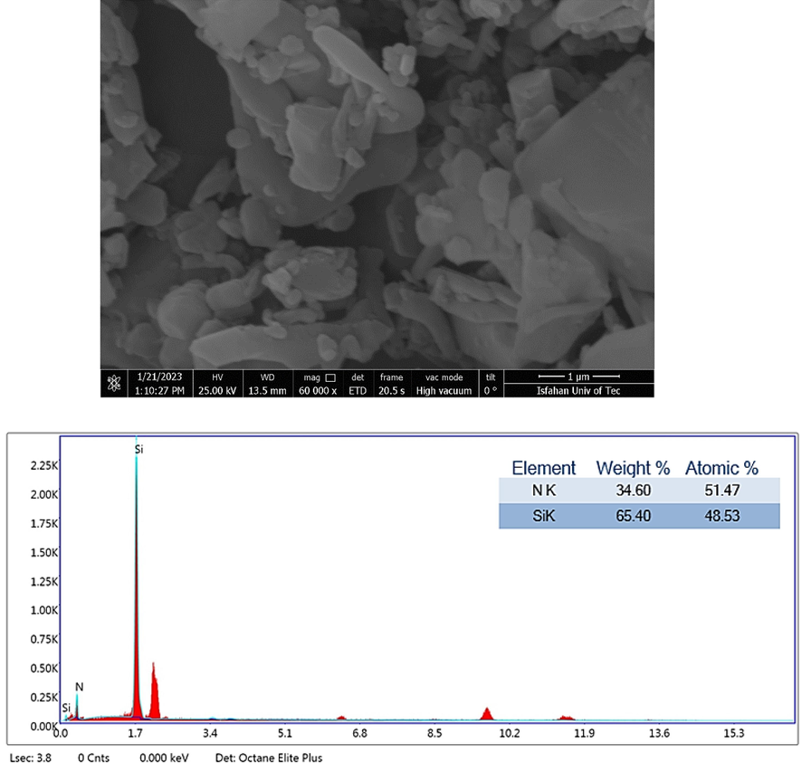
(a) scanning electron microscopic images of α- Si3N4 powder (b) EDS analysis of α- Si3N4 powder powder.
2.2 Preparation of the nanocomposite powder
First, α- Si3N4 nanopowder with 4 % alumina and 8% yttria nanoparticles as a sintering aid were dispersed in EMK solvent. Thereafter, the carbon fibers were dispersed in IPA solvent for 72 h on a magnetic stirrer. Subsequently, α- Si3N4 nanopowder and alumina/yttria nanopowders were added to a carbon fiber solution. Finally, the solution were dried at 70 °C. Fig. 2 displays the chart of the
nanocomposite powder preparation.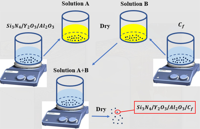
Schematic of the
nanocomposite powder preparation.
2.3 Sintering of the nanocomposite powders
The
powders were consolidated by the 10 ton-1000A SPS machine. In this method, 1.3227 g of α- Si3N4 /carbon fiber powder alongside the sintering aids (Table 1) in the SPS apparatus was exposed to a vacuum atmosphere (around 0.1 Tor) at 1750, 1800, and 1850 °C with 200 °C/min heating rate, as well as times of 10, 15, and 20 min at 70 MPa. Then, the polished sample was investigated for structural, density, hardness, COF, abrasion test, plus XRD and FE-SEM characterizations.
Sample code
Sintering time (min)
Sintering temperature (°C)
Sintering pressure (MPa)
1
10
1750
70
2
10
1800
70
3
10
1850
70
4
15
1850
70
5
20
1850
70
2.4 Characterization
2.4.1 X-ray diffraction (XRD) patterns
X-ray diffraction test (ASENWARE, AW-DX300) was used with a CuKα (1.5406 Å) aanode at the 2θ range of 10-80° To detect the phases. The phase detection of the XRD patterns was done by X Pert HighScore software.
The crystallite size was determined by Relation (1)(Nath et al., 2020; Wang et al., 2020; Kuang et al., 2018).
where, β is FWHM, Ɛ is the strain value, A is a constant number equal to 1, λ equalls to λ = 0.15406 nm, d is the crystallite size, and θ is the reflection angle.
The lattice constant (a) can be measeared by Eq. 2:
2.4.2 Scanning electron microscopy
FE-SEM micrographs was taken on MIRA3 LMU model made in TESCAN comany (Czech Republic). To detect the elemental analysis energy dispersive spectroscopy (EDS) was used.
2.4.3 Determining the density through the Archimedes principle
For measuring the density of the samples, the Archimedes principle was used according to the ASTM C373 standard. First, the dry weight of the samples (D) was measured using a balance with four decimal digits. Next, the samples were placed inside 100 °C water for 2 h, and once cooled and kept in water for 12 h, the suspended weight of the samples (S) in water was measured. Eventually, the extra water from the samples was removed using a moist cloth, and immediately their saturated weight (M) was measured. The bulk density (B) was calculated by Relation (3) (A.J. Standard, 2002).
The apparent porosity also known as open porosity (A.P) and the true porosity with closed and open porosity (T.P) were calculated by Relations (4) and (5).
2.4.4 Vickers microhardness measurement
EMCO Vickers test (M4U-250 model) was performed on surface of samples. The surface of each sample was tested eight times (ASTM C1327-15, 2019; Cao et al., 2023; Xie et al., 2021).
2.4.5 Fracture toughness
Fracture toughness was calculated by measuring the (mean) length of the radial cracks resulting from the Vickers indentation edges by using Eqs. (2)–(6) (Anstis et al., 1981; Zhu et al., 2017).
2.4.6 Determining coefficient of friction
In determining the coefficient of friction, an alumina pin applies an accurate force on the sample. The abrasion coefficient of the material and the pin is obtained by evaluating the extent of loss of the material along the experiment (ASTM, 2017; Shi et al., 2023).
The abrasion investigation was done without any lubricator within the temperature range of 20–25 °C, humidity of 25–35 %, and stable linear speed at a 500 m interval. The applied load (P) was 5 N (500 g). The abrasion rate (Wr) was computed via formula (7).
2.4.7 Determining the bending strength of the three-point bending test
There are many methods for evaluating the mechanical properties of materials and composites (Gao et al., 2023; Zhang et al., 2022; Chen et al., 2020; Xie et al., 2021; Samadi et al., 2021; Ndiwe et al., 2023). To reduce the costs and executive problems of the tensile test for the ceramics, their strength is often measured using a bending test. This investigation was done based on the ASTM D790 standard. The major advantage of the bending test, in addition to lower cost, is the simple geometry of the sample. The samples have a rectangular or cylindrical geometry, and the maximum tensile stress across the rod or beam occurs when the sample is broken, which is called the rupture modulus. For the ceramics, this test can be executed when the distance between the inner rollers is far larger than the height of the sample. Other terms are also used in addition to rupture modulus such as bending strength, fracture strength, and bend strength. The weakness of the bending test is stress distribution, which is very complex and nonuniform especially when the major defect of the sample has occurred inside the sample. A three-point bending test was used to calculate flexural strenth of samples. (Hassfield model, England). The bending strength (σr) for each sintered body was measeared by Eq. (8) (MPa) (ASTM D790, 1997).
3 Results and discussion
3.1 Representation of precursors
Fig. 3 displays the XRD results of the
powder; Fig. S1 (see supporting information file) indicates the carbon fiber, Fig. S2 shows the Al2O3, and Fig. S3 reveals the Y2O3. According to the XRD test, α- Si3N4 nanopowder has a hexagonal crystalline structure. In the silicon nitride alpha powder, 10 % beta phase was observed (the beta phase percentage was confirmed by MAUD software). Base on the XRD results, the Al2O3 nanoparticle is a blend of alumina α phases with a rhombohedral and monoclinic crystalline system. Based on the halo observed in Fig. S1 as well as the lack of diffraction of the graphite crystalline phase, The carbon fiber phase is amorphous.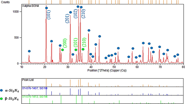
XRD results of
powder.
Fig. 4 indicates the XRD results of powder sample 2 (2o%Cf/Si3N4) before the sintering. The main detected phases included silicon nitride alpha and beta, plus alumina, yttria, and carbon sintering aids as boosters. Fig. 5 indicates the results of the XRD of samples 1, 2, and 3 after the sintering. By comparing Figs. 4 and 5, it was seen that after the sintering step, the SiO2 phase has created. Fig. 6 also shows the results of the XRD of samples 4 and 5 after the sintering. In these samples, again after the sintering, the SiO2 phase has been formed.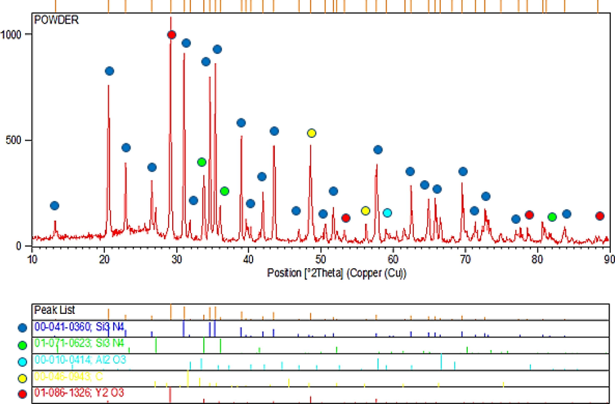
XRD results of Cf/α-Si3N4 powder before sintering step.
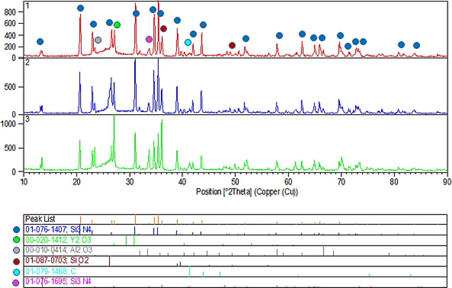
XRD results of sintered samples 1, 2, and 3.
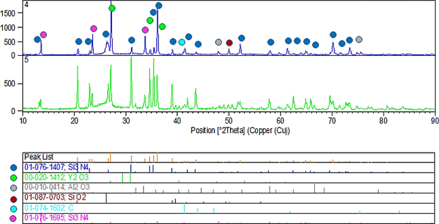
XRD results of sintered samples 4 and 5.
According to Fig. 6, sample 5 has the dominant alpha and beta silicon nitride hexagonal phase. The diffraction at 2θ of 23, 27 and 36° corresponds to the (1 1 0), (2 0 0) and (2 1 0) planes of the α-Si3N4 phase, respectively. The reflections located at 7.3, 7.6 and 66.1 ° is belonged to the facets of (0 0 3), (2 1 5) and (8 3 1) in the β-Si3N4 phase.
3.2 SEM images
The obtained data of SEM Imaging images corresponding to sintered samples are displayed in Fig. 7. According to SEM images, Carbon fiber with a length of 144–24 µm is well distributed in the silicon nitride powder. In sample 2, some agglomeration of nanoparticles and carbon fiber is detected. The better the carbon fiber is dispersed across the Si3N4 substrate and the less agglomeration, the more suitable heat transfer and conductivity will be during the sintering process (Ghasemi et al., 2023).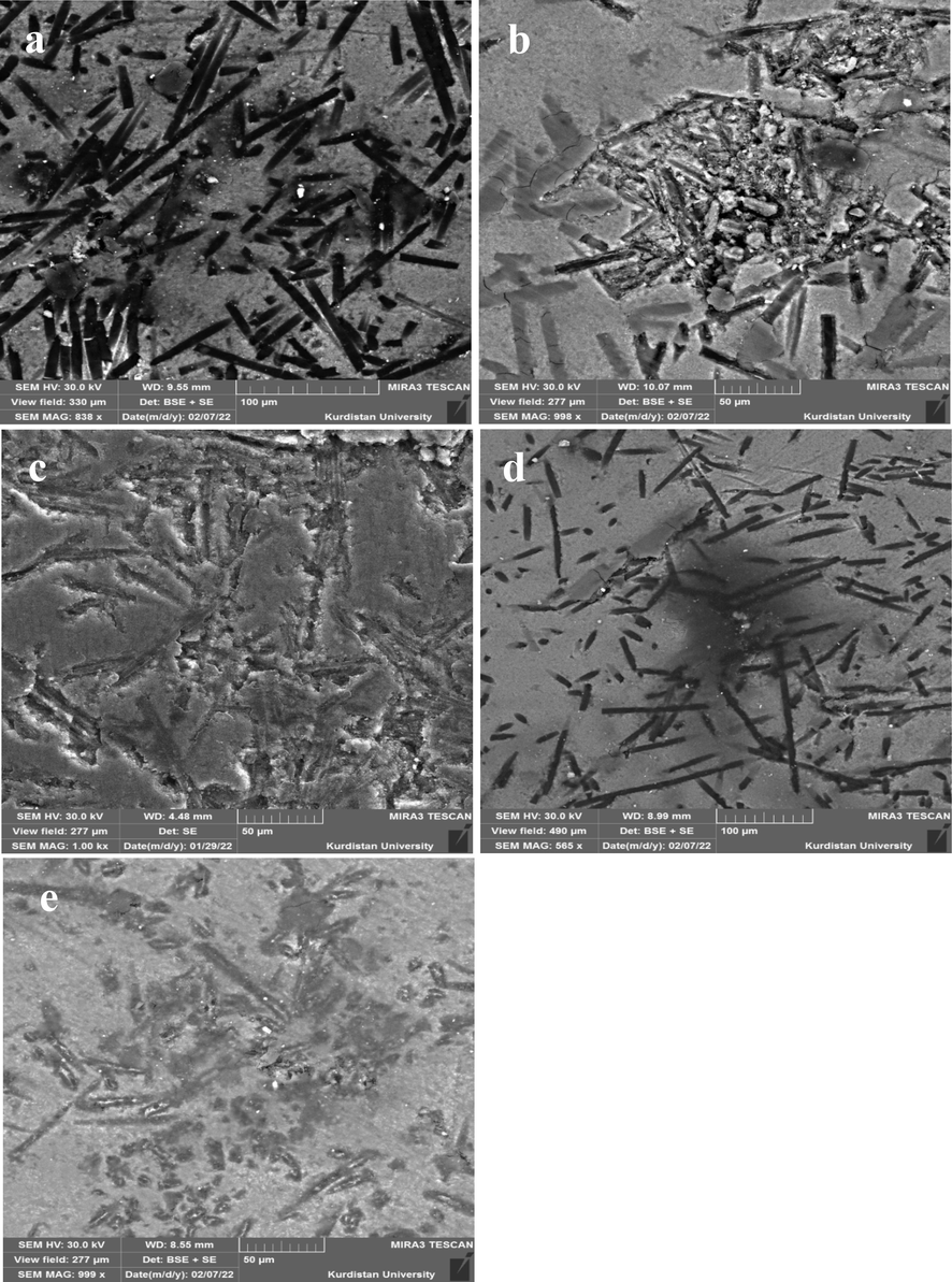
FESEM images of sintered samples, a) sample 1, b) sample 2, c) sample 3, d) sample 4, e) sample 5.
Fig. 8 demonstrates the results of the EDS test of the sintered specimen 5. The results show that the elements related to each of the phases of carbon and silicon nitride as well as sintering aids have been distributed inside the sample. Fig. S6 (see supporting information file) illustrate the SEM pictures and EDS mapping of the elements distributed in the silicon nitride-carbon fiber composite with different sintering aids.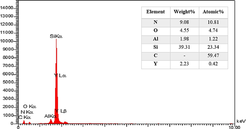
EDS analysis results of sample 5.
3.3 Results of density
The density of the specimens at various times and temperatures was computed via the Archimedes principle. The density of the alpha silicon nitride sintered samples at a time of 10 min, pressure of 70 MPa, as well as temperatures of 1750, 1800, and 1850 °C was obtained at 91.11 %, 92.73 %, and 93.03 % respectively. The obtained data from Archimedes' principle exhibited that the density would grow with an elevation of the sintering temperature due to major diffusion and elimination of the pores of the sample. The relict porosity for the sample sintered at 1750, 1800, and 1850 °C was obtained at 8.89 %, 7.27 %, and 6.97 % respectively.
The density of the alpha silicon nitride specimens under the pressure of 70 MPa, temperature of 1850 °C, as well as times of 15 and 20 min were 95.31 and 96.53 % respectively. The obtained result displayed that the density rises with the prolongation of the sintering time due to the diffusion of particles and removal of porosity. The relict porosity for the sintered samples at times of 15 and 20 min was 4.69 and 3.47 % respectively.
3.4 Hardness of the sintered samples
The hardness of sintered samples was calculated by the Vickers hardness test. The hardness measurement results indicated that the alpha silicon nitride samples sintered at 1750, 1800, and 1850 °C had hardness values of 536, 607, and 916 Vickers respectively. The results show that the composite hardness increases with an elevation of the sintering temperature. The results are in line with the density of the fabricated composite, whereby the specimen sintered at 1850 °C and time of 10 min had the maximum density and hardness. The presence of numerous pores in the structure can be the reason for the low hardness of the sample sintered at 1750 °C. The hardness of the alpha silicon nitride samples sintered at 1850 °C, as well as times of 15 and 20 min, was obtained at 1234 and 1433 Vickers respectively. The obtained result also concurs with the density of the fabricated composite, whereby the specimen within 20 min and at 1850 °C found the greatest density and hardness. The high hardness of Cf/Si3N4 sintered at 1850 °C for 20 min is due to the high density and low porosity of this sample.
3.5 Surface roughness
To check the surface roughness of the sintered samples, a roughness test was performed. The average surface roughness of the specimen (Ra) before the abrasion investigation was obtained as 0.58, 0.62, 0.69, 0.59 and 0.76, respectively (Fig. S7). According to the obtained results, all samples with grade N6 had a very smooth surface.
3.6 COF of the sintered samples
The wear rate (according to Formula (7)) of the sintered specimen was obtained at 14.4 ×
g/N.m, respectively. The results showed that the specimen with the maximum density had the lowest abrasion rate. The COF of the consolidated disc was 0.72, 0.6, 0.5, 0.49, and 0.46 respectively (Fig. 9). Among consolidated disc, sample 5 exhibited a stable COF along 500 m. Also, sample 5 has shown the closest coefficient of friction to the one required for the train brake disc (COF = 0.3–0.4) (Ghasemi et al., 2023; Naslain et al., 1999).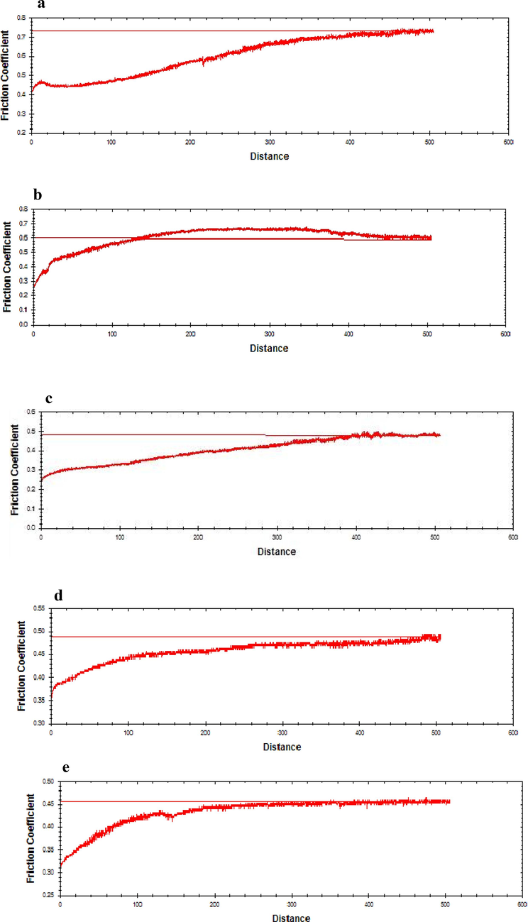
Friction coefficient curves in terms of the sliding distance of the sintered samples: a) sample 1, b) sample 2, c) sample 3, d) sample 4, and e) sample 5.
3.7 Bending strength of the sintered specimen
To check the bending strength of the specimen, a three-point bending test was performed. Based on the curves in Fig. S8, the bending strength of samples 1, 2, and 3 was obtained at 252, 205, and 247 MPa respectively. The results show that with temperature elevation, the bending strength diminishes.
The bending strength of specimens 4 and 5 were obtained at 248 and 256 MPa respectively. The greater bending strength of sample 5 is due to the fact that it has numerous stretched grains (Wang et al., 2013) of beta–Si3N4 plus a few numbers alpha phase grains (20 % α- Si3N4, 79 % beta Si3N4 obtained using Rietveld method) (Fig. S4, see the appendix file).
Fig. 10 indicates the SEM pictures of the fracture surface of the specimen. The images show that carbon fibers have contributed to improving the strength of samples through fiber pull-out mechanism.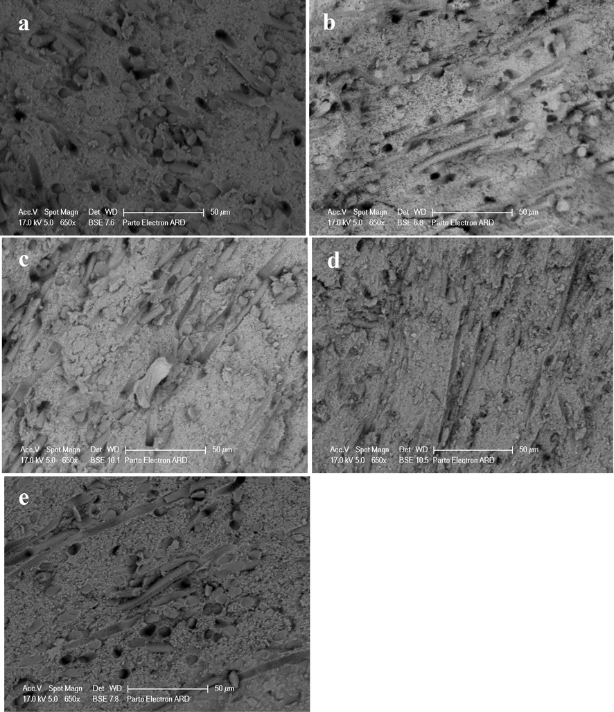
FESEM images of the fracture surface of the sintered samples: a) sample 1, b) sample 2, c) sample 3, d) sample 4, and e) sample 5.
3.8 Inspecting the fracture toughness of sintered specimen
The fracture toughness of the sintered specimen was obtained at 1.33, 2.68, 3.25, 3.97, and 5.87 MPa.m0.5 respectively (Fig. S9). The results showed that as density increased, so did the fracture toughness of the specimen.
The comparison of flexural strength, COF, and density of Cf/Si3N4 with other brake discs (Fan et al., 2007; Krenkel et al., 2004; Zahabi et al., 2023; Agarwal et al., 2016; Lange, 1975; Zhang et al., 2005; Krenkel, 2004; Zhao, 2023) made from carbon fiber reinforced ceramic matrix is shown in Table 2. As can be seen in Table 2, the toupghness of Cf/Si3N4 is close to the Cf/SiC disc and the flextural strength of Cf/Si3N4 is higher than Cf/SiC produced by CVI and LSI methods (Krenkel et al., 2004; Krenkel, 2004). The flexural strength of Cf/Si3N4 is lower than Cf/SiC produced by Zahabi and coworkers (Zahabi et al., 2023) due to different sintering aids and the density of their work. Other works was also investigate their properties of each component with experimental analysis and simulation method (Zhao, 2023; Zhang et al., 2023d; Zhang et al., 2023b; Zhang et al., 2023c; Gao et al., 2022; Zhang et al., 2022; Luo et al., 2023; Wang et al., 2022; Zhu et al., 2021; Yang et al., 2022; Tangal et al., 2022; Ogunjiofor and Ayodele, 2023; Wang et al., 2022, Ghasemi, M. et al., 2023, Mich et al., 2023).
Composite
Method
Bending Strength (MPa)
Hv
Toupghness (MPa.m0.5)
COF
Wear rate (g/N.m)
Density (%)
Ref.
Cf/SiC
SPS
–
1500–2400
5.72
0.42
–
89.5–92
(Agarwal et al., 2016)
Cf/SiC
SPS
1650–2850
3.66–4.50
0.25–0.50
–
85–96
(Lange, 1975)
Cf/SiC
SPS
200–479
1450–3211
–
0.41–0.53
5.2 × 10⁻⁶
85–96
(Zahabi et al., 2023)
Cf/SiC
CVI & LSI
–
0.41
95
(Zhang et al., 2005)
Cf/SiC
LSI
165
0.41
96.5
(Fan et al., 2007)
Cf/SiC (Krenkel company)
CVI
160
0.34
95.5
(Krenkel et al., 2004)
DLR Cf/SiC
LSI
300
–
95
(Krenkel, 2004)
(Cf/α-Si3N4)
SPS
256
1433
5.87
0.46
4.4×
96.53 %
- Current work
4 Conclusion
-
The results showed that with the increase of temperature and sintering time, the density of the samples increased from 91.11 % to 96.53 % and the hardness of the specimen improved from 536 Hv to 1433 Hv due to lower porosity (higher density of a sample with increasing sintering temperature) in the samples.
-
Since the COF for air brake disc would be around 0.3–0.4, and the porosity of the specimen would be within 5–8 %, the specimen sintered within 20 min and at 1850 °C (sample 5) had the closest value to train brake disc features.
-
Since the fracture toughness values of the train brake disc would be about 4–6 MPa. , thus the sintered sample 5 with a fracture toughness of 5.87 MPa. fell within the train brake disc range.
-
The results revealed that the specimen with the maximum density (sample 5) had a minor abrasion rate (4.4 × g/N.m).
Availability of data and materials
The obtained data are available upon reasonable request.
CRediT authorship contribution statement
Saeed Hoseinzadeh: Conceptualization, Data curation, Investigation, Methodology, Project administration, Writing - original draft. Gholamreza Gordani: Conceptualization, Data curation, Funding acquisition, Investigation, Methodology, Project administration, Supervision, Validation. Majid Tavoosi: Data curation, Funding acquisition, Methodology, Software, Validation. Mohammed Ridha H. Alhakeem: Conceptualization, Funding acquisition, Methodology, Resources, Validation. Mohammed Al-Bahrani: Conceptualization, Funding acquisition, Visualization. Mohammad Reza Loghman-Estarki: Conceptualization, Data curation, Funding acquisition, Investigation, Methodology, Project administration, Resources, Supervision, Validation, Writing - review & editing.
Declaration of Competing Interest
The authors declare that they have no known competing financial interests or personal relationships that could have appeared to influence the work reported in this paper.
References
- A.J. Standard, bulk density, apparent density, and A.I. apparent specific gravity of fired whitewares products, West Conshohocken, PA, ASTM C373–88. 2002.
- A pin-on-disc study of the rate of airborne wear particle emissions from railway braking materials. Wear. 2012;284:18-29.
- [Google Scholar]
- Tribo-mechanical characterization of spark plasma sintered chopped carbon fibre reinforced silicon carbide composites. Ceram. Int.. 2016;42(16):18283-18288.
- [Google Scholar]
- A critical evaluation of indentation techniques for measuring fracture toughness: I, direct crack measurements. J. Am. Ceram. Soc.. 1981;64(9):533-538.
- [Google Scholar]
- American Society for Testing and Materials. standard test method for wear testing with a pin-on-disk apparatus. Conshohocken: ASTM West; 2017.
- standard test method for Vickers indentation hardness of advanced ceramics. Conshohocken: ASTM West; 2019.
- ASTM D790, 1997. Standard test methods for flexural properties of unreinforced and reinforced plastics and electrical insulating materials.
- In situ production of B4C and FeV enriched composite surface on low carbon steel by cast sintering technique. Metall. Mater. Eng.. 2023;29(1):70-79.
- [Google Scholar]
- Si3N4–TiN nanocomposite by nitration of TiSi2 and consolidation by hot pressing and spark plasma sintering. J. Nanosci. Nanotechnol.. 2009;9(11):6381-6389.
- [Google Scholar]
- Preparation and characterization for the thermal stability and mechanical property of PLA and PLA/CF samples built by FFF approach. Materials. 2023;16(14):5023.
- [Google Scholar]
- Effects of post-weld heat treatment on the microstructure and mechanical properties of laser-welded NiTi/304SS joint with Ni filler. Mater. Sci. Eng.: A. 2020;771:138545.
- [Google Scholar]
- Microstructural evolution in graphene nanoplatelets reinforced magnesium matrix composites fabricated through thixomolding process. J. Alloy. Compd.. 2023;940:168824
- [Google Scholar]
- Analysis of tribological behaviour of pad–disc contact in railway braking: Part 1. Laboratory test development, compromises between actual and simulated tribological triplets. Wear. 2007;262(5–6):582-591.
- [Google Scholar]
- Microstructure and properties of 3D needle-punched carbon/silicon carbide brake materials. Compos. Sci. Technol.. 2007;67(11–12):2390-2398.
- [Google Scholar]
- Ceramic matrix composites for disk brakes and their manufacturing technologies. Ceram. Mater. Compon. Engines 2001:13-19.
- [CrossRef] [Google Scholar]
- Grinding and lapping induced surface integrity of silicon wafers and its effect on chemical mechanical polishing. Appl. Surf. Sci.. 2022;599:153982
- [CrossRef] [Google Scholar]
- Molecular simulation of the plastic deformation and crack formation in single grit grinding of 4H-SiC single crystal. Int. J. Mech. Sci.. 2023;247:108147
- [Google Scholar]
- Holme, J.D., 2002. Disc brake rotor with a grey cast iron composition. European Patent EP1034317.
- The effect of carbon fiber length on the microstructure, selected mechanical, wear, and thermal conductivity of C f/SiC composite fabricated via spark plasma sintering (SPS) method. Journal of the Korean Ceramic Society. 2023;19:1-4.
- [Google Scholar]
- A comparative study of black-box and white-box data-driven methods to predict landfill leachate permeability. Environ. Monit. Assess.. 2023;195(7):862.
- [Google Scholar]
- Self-standing boron nitride bulks enabled by liquid metal for thermal management. Mater. Horiz. 2023
- [CrossRef] [Google Scholar]
- Carbon fiber reinforced CMC for high-performance structures. Int. J. Appl. Ceram. Technol.. 2004;1(2):188-200.
- [Google Scholar]
- Design, manufacture and quality assurance of C/C-SiC COMPOSITES FOR SPACE TRANSPORTATION SYSTems. In: 28th International Conference on Advanced Ceramics and Composites b: Ceramic Engineering and Science Proceedings. Vol vol. 25. Hoboken, NJ, USA: John Wiley & Sons, Inc.; 2004. p. :49-58.
- [Google Scholar]
- Application of the thermodynamic extremal principle to diffusion-controlled phase transformations in Fe-CX alloys: Modeling and applications. Acta Mater.. 2018;159:16-30.
- [Google Scholar]
- Hot-pressing behaviour of silicon carbide powders with additions of aluminium oxide. J. Mater. Sci.. 1975;10(2):314-320.
- [Google Scholar]
- Enhanced circular dichroism by F-type chiral metal nanostructures. Photonics. 2023;10(9):1028.
- [CrossRef] [Google Scholar]
- Spark plasma sintering of ceramic matrix composites with self healing matrix. Ceramic Engineering and Science Proceedings. 2014;35:177-186.
- [Google Scholar]
- Wear maps of HIP sintered Si3N4/MLG nanocomposites for unlike paired tribosystems under ball-on-disc dry sliding conditions. J. Eur. Ceram. Soc.. 2017;37(14):4357-4369.
- [Google Scholar]
- Matovic, B., 2003. Low temperature sintering additives for silicon nitride.
- Optimization of solvent extraction conditions of Cambodian soybean oil using response surface methodology. J. Food Technol. Res.. 2023;10(1):1-10.
- [Google Scholar]
- Micro/minicomposites: a useful approach to the design and development of non-oxide CMCs. Compos. A Appl. Sci. Manuf.. 1999;30(4):537-547.
- [Google Scholar]
- The effects of train brake delay time on in-train forces. Proc. Inst. Mech. Eng., Part f: J. Rail Rapid Transit. 2010;224(6):523-534.
- [Google Scholar]
- X-ray diffraction analysis by Williamson-Hall, Halder-Wagner and size-strain plot methods of CdSe nanoparticles-a comparative study. Mater. Chem. Phys.. 2020;239:122021
- [Google Scholar]
- Numerical and Experimental Investigations of Mechanical Properties of AW 6005–T6 Aluminium Alloy Butt Weld Joint Using GMAW Process. Metall. Mater. Eng.. 2023;29(1):16-36.
- [Google Scholar]
- Utilization of response surface methodology in optimization of locally sourced aggregates. J. Asian Sci. Res.. 2023;13(1):54-67.
- [CrossRef] [Google Scholar]
- Pak, Z.S., 2001. Cf/SiC/C composites for frictional application. KRENKEL W, NASLAIN R, and SCHNEIDER H. High Temperature Ceramic Matrix Composites. Weinheim: Federal Republic of Germany, 825.
- A novel CMC material for train brake systems. Ceramics-Process., Reliab., Tribol. Wear. 2000;12:108-113.
- [Google Scholar]
- Prediction of the dynamic pressure distribution in hydraulic structures using soft computing methods. Soft. Comput.. 2021;25:3873-3888.
- [Google Scholar]
- Tribology and dynamic characteristics of textured journal-thrust coupled bearing considering thermal and pressure coupled effects. Tribol. Int.. 2023;180:108292
- [Google Scholar]
- Effect of nano yttria-stabilized zirconia on properties of Ni-20Cr composite coatings. J. Electrochem. Sci. Eng.. 2022;12(5):901-909.
- [Google Scholar]
- The rheological performance of shear-thickening fluids based on carbon fiber and silica nanocomposite. Phys. Fluids. 2023;35(3)
- [CrossRef] [Google Scholar]
- A WSe2@ poly (3, 4-ethylenedioxythiophene) nanocomposite-based electrochemical sensor for simultaneous detection of dopamine and uric acid. J. Electrochem. Sci. Eng.. 2022;12(6):1251-1259.
- [Google Scholar]
- Evolution of crystallographic orientation, precipitation, phase transformation and mechanical properties realized by enhancing deposition current for dual-wire arc additive manufactured Ni-rich NiTi alloy. Addit. Manuf.. 2020;34:101240
- [Google Scholar]
- Analysis of position, pose and force decoupling characteristics of a 4-UPS/1-RPS parallel grinding robot. Symmetry.. 2022;14(4):825.
- [CrossRef] [Google Scholar]
- Transparent ceramics: Processing, materials and applications. Prog. Solid State Chem.. 2013;41(1–2):20-54.
- [Google Scholar]
- Air plasma-sprayed high-entropy (Y0.2Yb0.2Lu0.2Eu0.2Er0.2)3Al5O12 coating with high thermal protection performance. J. Adv. Ceram.. 2022;11(10):1571-1582.
- [CrossRef] [Google Scholar]
- Microstructure and mechanical properties of ultrasonic spot welding TiNi/Ti6Al4V dissimilar materials using pure Al coating. J. Manuf. Process.. 2021;64:473-480.
- [Google Scholar]
- Microstructure and mechanical properties of ultrasonic spot welding TiNi/Ti6Al4V dissimilar materials using pure Al coating. J. Manuf. Process.. 2021;64:473-480.
- [Google Scholar]
- Integrating tough Antheraea pernyi silk and strong carbon fibres for impact-critical structural composites. Nat. Commun.. 2019;10(1):3786.
- [Google Scholar]
- Correlating multi-scale structure characteristics to mechanical behavior of Caprinae horn sheaths. J. Mater. Res. Technol.. 2022;21:2191-2202.
- [CrossRef] [Google Scholar]
- The effect of alumina-based sintering aid on the microstructure, selected mechanical properties, and coefficient of friction of Cf/SiC composite prepared via spark plasma sintering (SPS) method. Ceram. Int.. 2023;49(10):15253-15265.
- [Google Scholar]
- Screen-printed carbon electrode/natural silica-ceria nanocomposite for electrochemical aptasensor application. J. Electrochem. Sci. Eng.. 2022;12(6):1225-1242.
- [Google Scholar]
- Developing trends in disc bralke technology for rail application. Mater. Sci. Technol.. 1998;14(9–10):857-863.
- [Google Scholar]
- A novel parametric model for nonlinear hysteretic behaviours with strain-stiffening of magnetorheological gel composite. Compos. Struct.. 2023;318:117082
- [Google Scholar]
- Ab initio molecular dynamics calculations on electron ionization induced fragmentations of C4F7N and C5F10O for understanding their decompositions under discharge conditions. PCCP. 2023;25(10):7540-7549.
- [CrossRef] [Google Scholar]
- Influence of oxygen on solid carbon formation during arcing of eco-friendly SF6-alternative gases. J. Phys. D Appl. Phys.. 2023;56(36):365502
- [CrossRef] [Google Scholar]
- Determination and assessment of a complete and self-consistent electron-neutral collision cross-section set for the C4F7N molecule. J. Phys. D Appl. Phys.. 2023;56(13):134001
- [CrossRef] [Google Scholar]
- A Ferrotoroidic Candidate with Well-Separated Spin Chains. Adv. Mater. (weinheim). 2022;34(12):e2106728.
- [Google Scholar]
- Molecular dynamics simulation and experimental study of tin growth in SAC lead-free microsolder joints under thermo-mechanical-electrical coupling. Mater. Today Commun.. 2022;33:104301
- [Google Scholar]
- Braking behavior of C/SiC composites prepared by chemical vapor infiltration. Int. J. Appl. Ceram. Technol.. 2005;2(2):114-121.
- [Google Scholar]
- Understanding and design of metallic alloys guided by phase-field simulations. npj Comput. Mater.. 2023;9(1):94.
- [CrossRef] [Google Scholar]
- Current research status of interface of ceramic-metal laminated composite material for armor protection. Acta Metall. Sin.. 2021;57(9):1107-1125.
- [Google Scholar]
- Outstanding wear resistance of plasma sprayed high-entropy monoboride composite coating by inducing phase structural cooperative mechanism. Appl. Surf. Sci.. 2023;616:156516
- [Google Scholar]
- Ameliorated longitudinal critically refracted—Attenuation velocity method for welding residual stress measurement. J. Mater. Process. Technol.. 2017;246:267-275.
- [Google Scholar]
- Effect of heat input on interfacial characterization of the butter joint of hot-rolling CP-Ti/Q235 bimetallic sheets by Laser + CMT. Sci. Rep.. 2021;11(1):10020.
- [CrossRef] [Google Scholar]
Appendix A
Supplementary material
Supplementary data to this article can be found online at https://doi.org/10.1016/j.arabjc.2023.105378.
Appendix A
Supplementary material
The following are the Supplementary data to this article:Supplementary data 1
Supplementary data 1


