

Translate this page into:
Fibrin Clot Degradation by Polyaniline-Coated AuNP Using Laser Photolysis
⁎Corresponding authors. ralshammari@ksu.edu.sa (Riyadh H. Alshammari), tahanis@ksu.edu.sa (Tahani S. Algarni)
-
Received: ,
Accepted: ,
This article was originally published by Elsevier and was migrated to Scientific Scholar after the change of Publisher.
Abstract
Abstract
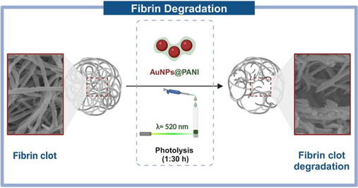
Fibrin clots are crucial for hemostasis and the healing of wounds; nevertheless, excessive blood clotting plays an important role in many chronic diseases, including cardiovascular disease. In this study, we demonstrated the effect of the prepared AuNPs@PANI core/shell on the formed fibrin network. The synthesis of nanoparticles combining electrically conducting polymers polyaniline (PANI) and gold nanoparticles (AuNPs) is an appealing field of research currently because of their physical features and prospective applications in biochemistry. AuNPs showed surface plasmonic resonance (SPR) properties in the visible region at 520 nm then, after coating with PANI, there was a dramatic red shift to 610 nm. The morphological conformation was confirmed by characterization at the microscopic (TEM, SEM, EDX). The PANI shell plays a crucial role in this system, first enhances the stability of AuNPs core; also, the surface of the PANI shell has positive charges (zeta potential = +17.8 mV), leading to electrostatic interactions with fibrin clots that have negatively charged surfaces. The synthesized core/shell AuNPs@PANI showed good efficiency for degrading fibrin networks under 1:30 h of irradiation by an external source of laser light, which is a result of AuNPs’ ability to absorb light at 520 nm. The degradation of fibrin was observed using a scanning electron microscope (SEM), which showed a clear change in the shape of the network. The appearance of fibrous endings and gaping indicates the beginning of the degradation and melting of the fibrin network in different sites of the clot. Overall, this method could have a major influence on disease states, for example, deep vein thrombosis, through a localized, catheter-based approach.
Keywords
AuNP
Fibrin clot
Laser photolysis
Polyaniline
Surface modification

1 Introduction
Blood clots are crucial for hemostasis and the healing of wounds; nevertheless, excessive blood clotting plays an important role in many chronic diseases, including cardiovascular disease. The blood clot, or thrombus, is a complex structure made up of many blood components. The most essential of which are platelets and red blood cells encased within a fibrin netting. (Walker and Zaleski, 2014) Fibrin network is final product of polymerization of fibrinogen, which is a soluble glycoprotein normally found in human blood plasma with concentrations ranging 1.5–4 g/L. Fibrinogen biosynthesis production occurs in the hepatocytes, that is main component required for many biological processes, for example, hemostasis, wound healing, inflammation, and angiogenesis. Fibrinogen is a large, soluble molecule, but when converted to fibrin, it creates an insoluble clot, which is a biopolymer produced naturally at the end of the blood coagulation cascade by the action of the thrombin enzyme on fibrinogen, which is activated as a result of injury to the vessel wall or by activated blood cells (Weisel and Litvinov, 2017; Noori et al., 2017).
Fibrinogen consists of pairs of three polypeptide chains linked together by 29 disulfide bonds (Weisel and Litvinov, 2013; Li et al., 2015). Fibrin polymerization begins with the cleavage of the fibrinopeptides A (FpA) and B (FpB) of fibrinogen in the presence of thrombin to form the fibrin monomer. In the second step, monomeric fibrin spontaneously self-assembles to form fibrin oligomers, which extend to form two-stranded protofibrils. Protofibrils clump together laterally and longitudinally to form fibers, which branch to form a three-dimensional gelled network known as a blood clot (Weisel and Litvinov, 2013). The fibrin polymer is covalently crosslinked by the transglutaminase factor XIIIa, which is activated by the enzyme thrombin in the presence of calcium ions to form a mechanically and chemically more stable fibrin clot (Weisel and Litvinov, 2013).
When the clot complete hemostasis or wound healing function and are no longer needed in vivo, natural mechanisms arise for the removal of fibrin. Fibrin clot is processed through another series of enzymatic reactions known as the fibrinolytic system. Plasmin is the main fibrinolytic enzyme in vivo, which is a serine protease derived from the inactive precursor plasminogen that circulates in the blood. Briefly, plasminogen is converted to plasmin by plasminogen activators like tissue plasminogen activator (t-PA) on the fibrin surface. Therefore, fibrin serves as both a substrate and a cofactor for the fibrinolytic enzyme plasmin during fibrinolysis. Then, Plasmin cleaves fibrin at specific places after activation, releasing soluble fibrin. D-dimer is one of the smallest fibrin degradation products which is a product of two D-regions of the fibrin molecules connected by a y-y bond (Weisel and Litvinov, 2017; Noori et al., 2017).
The role of thrombin concentration in fibrin production and structure has garnered a lot of attention. High concentrations of thrombin result in dense networks and highly branched fibrin fibers, which are resistant to fibrinolysis. Low concentrations of thrombin, on the other hand, result in coarse networks of fibrin fibers but relatively unbranched fibrin fibers, and these clots are more prone to fibrinolysis (Kattula et al., 2017). In vivo, when vascular tissues are injured, a stable blood clot is formed as a result of fibrin polymerization to promote wound healing and prevent blood loss (Vilar et al., 2020). This results in a delicate balance between two processes: clotting (the transformation of fibrinogen into fibrin) and fibrinolysis (the degradation of fibrins). Any imbalance can cause thrombosis, which is the formation of a clot that prevents blood flow through a vessel (Weisel and Litvinov, 2017) and can cause many disease modalities, including cardiovascular disease, cancer, neurological disorders, obesity, diabetes, and amyloidosis (Vilar et al., 2020).
Acute thrombosis-induced blood vessel obstruction can result in significant blood flow reduction and organ dysfunction. Therefore, there must be a rapid restoration of blood flow. Both antithrombotic medications and surgical intervention are clinically effective treatment options for thrombus therapy, but, antithrombotic drugs continue to be the better option (Zhao et al., 2020). However, these medications may disrupt normal hemostatic functions or be unable to target the thrombus, which, as a dangerous side effect, can result in uncontrolled bleeding complications (Walker and Zaleski, 2014; Zhao et al., 2020).
The application of nanoparticles for treatment is very promising at the moment due to a number of potential advantages, including ease of preparation, optical characteristics, a large surface area to volume ratio meaning a large payload capacity, imaging diagnostics, and targeting ability (Walker and Zaleski, 2014; Kirichenko et al., 2019; Siddique and Chow, 2020). Nanoparticles are chemical substances that are produced and used on a very small scale and have at least one dimension smaller than 100 nm. The importance of nanoparticles was realized when researchers studied the effect of size on their physiochemical properties, specifically their optical properties, mechanical properties, and electrical properties. (Saleh, 2020) Recently, AuNPs have emerged as potential materials in a variety of biomedical applications, including cancer treatment (Yang et al., 2019; Mao et al., 2020), drug delivery, (Siddique and Chow, 2020; Du et al., 2018) bioimaging applications, diagnosis, (Kong et al., 2017) and fibrin clot degradation (Walker and Zaleski, 2014). One of the advantages of sphere-shaped AuNPs is their ease of preparation, which involves the reduction of gold ions Au (Noori et al., 2017)+ to the gold metal Au0 using appropriate reducing agents (Mao et al., 2020).
AuNPs exhibits unique localized surface plasmon resonance (LSPR), which is an optical phenomenon that describes the interaction between surface electrons of AuNPs and light (an electromagnetic wave), this leads to a light wave that is trapped within AuNPs having a wavelength smaller than light (Petryayeva and Krull, 2011). The LSPR wavelength position of AuNPs can be modified by modifying a number of parameters, including shape, size, structure, and the environment surrounding the surface of the AuNPs (Yang et al., 2015). Additionally, the thermal effects of AuNPs can be applied to cancer therapy, which is known as photothermal therapy (PTT). The targeted materials are irradiated by using an external source of laser light with high photothermal conversion efficiencies to heat (Zhang et al., 2018). This change may be attributed to the significant temperature difference between the biological medium and the hot surface of AuNPs, which causes an abrupt local hyperthermia and has an effect on cancer cells (Webb and Bardhan, 2014). Significantly, the resonance wavelength makes the AuNPs able to efficiently absorb radiation, meaning that when used in bioapplication and treatment, AuNPs can be targeted to specific tissues (Liu et al., 2021). Lasers are widely used in many fields, including science and medicine. One of the most important characteristics that distinguishes lasers from other light sources is the monochromaticity, coherency, and collimation of the beam. The laser wavelength also positively determines both the thermal effect and penetration depth. Monochromatic light sources contributed to the development of many technologies like superresolution imaging, cutting, and cauterization, as well as being used in biostimulation and photodynamic therapy (Szymański et al., 2021; Jurczyszyn et al., 2020).
The subsequent coating of AuNPs with different shells has been very successful in the preparation of active and stable nanoparticles (Engelbrekt et al., 2021). In general, the formation of a shell around the nanoparticles aims to modify the nanoparticles surface by using a wide functional group of organic/inorganic materials, such as polymers. The value of coating nanoparticles could be considerable when they not only protect the metal core but also play a key role in boosting biocompatibility and stability of nanoparticles and in applications like treatment and targeted delivery (Khatami et al., 2018). Among various types of conductive polymers PANI is the most common due to its ease of polymerization, low-cost, excellent thermal and environmental stability, large range of conductivity, biocompatibility, and optical and electrical properties (Mondal et al., 2014; Hou et al., 2015; Eisa et al., 2014). PANI has alternating single and double bonds to form its conjugated backbone, which is contents of π-bonds with overlapping p-orbitals and delocalization of π-electron, making PANI material promising for electron conductivity (Jayeoye et al., 2021). Liquid PANI ionic thermoelectric power and electrical conductivity data indicate that it is a p-type semiconductor (Babel and Hiran, 2021).
When AuNPs and PANI are combined to create core/shell nanoparticles, the AuNPs@PANI possess the merits of their inorganic and organic components and may also have new properties, and it improves electrochemical, and electrocatalytic activities as compared to pure PANI (Eisa et al., 2014; Bogdanovic et al., 2015). The AuNPs@PANI core/shell nanoparticles have been reported in many important potential applications, including biological applications (Hou et al., 2015; Jayeoye et al., 2021), catalysts for the reduction of aromatic nitro-compounds (Mondal et al., 2014; Li et al., 2016), agents for fibrin degradation (Alshammari et al., 2020), catalysts for dye degradation (Mondal et al., 2020), and electrocatalytic applications (Bogdanovic et al., 2015; Tan et al., 2017). Recent research has demonstrated that AuNPs/PANI nanorods are able to generate reactive oxygen species (ROS) upon irradiation with visible light and could therefore be used to degrade the fibrin clot network. that attributed this to the surface of the PANI shells containing positive charges capable of enhancing electrostatic interactions with fibrin (Alshammari et al., 2020). PANI plays an important role in this system, including: (1) The surface of the PANI shell has positive charges, leading to electrostatic interactions with fibrin clots that have negatively charged surfaces. (2) enhances the stability of AuNPs core and increases their biocompatibility.
On the other hand, the clot morphology and study of the gaps on fibrin clots can be used as a sensitive indicator of the state of the precursor protein because changes in the fibrinogen peptidic structure or even in the clotting conditions. For example, thrombin concentrations, will affect the way the protofibrils aggregate into the fully polymerized fibrin structure. Therefore, the fibrin clot degradation can be evaluated after addition of nanoparticles by the size of the gaps, the increase in the number of gabs, and the appearance of the fibers in scanning electron microscopy images (Walker and Zaleski, 2014; Alshammari et al., 2020). Walker et al. (Walker and Zaleski, 2014) mentioned that the low percentage of changes in surface morphology by small gold nanoparticles relative to the fiber size of fibrin leads to extrapolated changes in morphology on the micron scale, where the plasmon-excited photothermal method was used for nonenzymatic fibrin degradation.
In the present study, we reported the synthesis of AuNPs coated with PANI as core/shell nanoparticles using two-step methods. The AuNPs with spherical shapes were prepared by the reduction HAuCl4 in trisodium citrate. Then, the PANI shell around AuNPs is formed by the hydrothermal method. The efficiency of the synthesized nanoparticles AuNPs@PANI core/shell was studied for degradation of fibrin networks under irradiation by an external source of laser light at 520 nm through a study of their scanning electron microscope (SEM).
2 Material and methods
2.1 Chemicals
The solution of the gold (III) chloride trihydrate (HAuCl4·3H2O) was prepared in the laboratory by reacting gold metal with chlorine gas. (King et al., 2015) In detail, Hydrochloric acid (15 mL, 36 %) was added in a pressure-balancing dropping funnel, and slowly added drop-wise to a flask containing potassium permanganate (3.0 g, 19 mmol). This reaction generates chlorine gas which was passed into a two-neck round-bottom flask containing 100 mL ultrapure water and one pellet of gold (∼250 mg). Undissolved chlorine gas was bubbled through a solution of sodium thiosulfate (1.1 g, 7.0 mmol) dissolved in 50 mL of water. The reaction mixture was stirred at the selected temperature (40–60 °C) until all the gold dissolved.
Tri-sodium citrate (Na3C6H5O7·2H2O), and glucose anhydrous (C6H12O6, 99.0 %) were purchased from Winlab. Copper (II) acetate (Cu (COOCH3)2) and aniline (C6H5NH2) were purchased from BDH. Sodium chloride (NaCl) was purchased from lobe chemie. HEPES (4-(2-hydroxyethyl)-1-piperazineethanesulfonic acid). Fibrinogen from bovine plasma (≥75 % of protein is clottable), thrombin from bovine plasma (lyophilized powder, ≥2,000 NIH units/mg protein) was purchased from sigma. All solutions were prepared in deionized water and used without further purification steps unless otherwise indicated.
2.2 Sample characterization techniques
The absorption spectra of AuNPs and AuNPs@PANI core/shell were recorded using a UV–Visible Spectrophotometer (UV-2450), Shimadzu Corporation, Kyoto, Japan, in a quartz cell. The functional groups of the prepared samples were confirmed by recording infrared spectroscopy (FT-IR) on the Spectrum BX spectrometer (PerkinElmer, Waltham, USA) using KBr pellets of the samples. Dynamic light scattering (DLS) and zeta potential of the working particles were measured using a device from Malvern. A pH meter (Thermo, S-2STAR-E 0608 RevB) was used for pH measurements.
Additionally, the size and morphology of the samples were characterized using a transmission electron microscope (TEM) (JEOL, JEM 1400 Plus, USA). TEM samples were prepared by dripping the sample onto carbon-coated copper grids and then air-drying overnight. Scanning electron microscope (SEM) was carried out on a JEOL JSM-6060LV. The critical point dryer (Tousimis-Samdri-PVT-3D) was used to completely exchange ethanol in the fibrin samples with liquid CO2. The chemical composition of the core/shell nanoparticles was found by energy-dispersive X-ray analysis (EDX) connected with the SEM device.
2.3 Synthesis of AuNPs
Following the traditional Turkevich method. (Turkevich et al., 1951; Walker et al., 2011; Ojea-Jiménez et al., 2011) Briefly, in a flask, 100 mL of deionized H2O and 3 mL of freshly prepared trisodium citrate (1 % w/w) solution were added. Solution then heated up to 100 °C for 15 min. 1 mL of an aqueous solution of HAuCl4·3H2O (1 % w/w) was added, and the mixture was kept at the boiling point for 5 min. The solution immediately changed from colorless to light blue and finally brick-red color, indicating the formation of AuNPs.
2.4 Synthesis of AuNPs@PANI core/shell
The AuNPs coated with PANI as a shell were prepared using the hydrothermal synthetic method. (Alshammari et al., 2020) In the capacity of Teflon container were added 8 mL of AuNPs solution, which was prepared in advance, 20 μL of aniline, Cu(OAc)2·H2O (0.25 mL, 80 mM), 10 mL of deionized water, and a freshly prepared (2 mL, 2 M) aqueous solution of glucose. The mixture was then added to a steel bomb and heated at 160 °C in an oven for 2 h. Finally, after the steel bomb cooled naturally to room temperature for 1 h, the AuNPs@PANI core/shell nanoparticles were centrifuged at 10000 rpm for 15 min and washed twice with water.
2.5 Protein stock solution
The thrombin and fibrinogen solutions were separately synthesized in HBS buffer, pH = 7.3 (20 mM HEPES, 150 mM NaCl). First, A fibrinogen stock solution of 3.5 mg/mL in HBS buffer was prepared, and every 150 μL was placed in small plastic tubes and frozen until later use. In a similar method, 50 U/mL thrombin was dissolved, partitioned into small plastic tubes, and frozen until use.
2.6 Fibrin clot preparation
Thrombin (12 μL, 50 U/mL) and fibrinogen (300 μL, 3.5 mg/mL) were mixed, and then quickly, 50 μL of the mixture was injected into short glass tubes, where these tubes were made with open ends, 4 cm in length and 4 mm in diameter, and one of their ends was closed using parafilm before adding the solution to make fibrin clot removal easier for later characterization. And then, the fibrin clots were left in the tubes for 1 h without moving to ensure complete formation of the fibrin network.
2.7 Photolysis of fibrin clot
After the complete formation of a fibrin clot, 50 μL of the previously prepared nanoparticle solution (AuNPs@PANI core/shell or AuNPs) was added over the fibrin clot. Then photolysis of the samples was carried out for 1:30 h using laser light of a specific wavelength of 520 nm with 300 mW. After that, the modified clot was separated from the tube for later characterization.
2.8 Sample preparation for SEM
Fibrin clots were washed with different concentrations of ethanol and water for 45 min each step (20 %, 40 %, 60 %, 80 %, and 100 % of ethanol). 2 % glutaraldehyde was added and left overnight at 4 °C to maintain the crosslinking of the fibrin clot obtained for SEM imaging. After warming the clot to room temperature, it was washed again with 100 % ethanol and dried using a CO2 critical point dryer. Create critical conditions for CO2; the chamber containing the samples and liquid CO2 was heated to 36 °C at a pressure above 1072 psi. Such conditions were then maintained for about 4 min. The sample was sputter-coated with Au to prepare it for SEM imaging.
2.9 Statistical calculations of the gaps area
Image J software was used to analyze and process the SEM microscopy image of the fibrin network for characterization and measure the gaps at three different locations for each sample. The threshold feature in the Image J software was used to determine the appropriate threshold for the SEM image. An area of approximately 500 gaps was measured for each SEM image. In particular, the gaps were measured in three SEM images per sample (i.e., the total number of gaps measured for each sample is at least 1500). (Morais et al., 2021; Feng et al., 2019; Hartig, 2013) Gaps smaller than 1 nm were excluded. After that, the percentage was calculated for the gaps. All SEM micrographs used in the statistical analysis of the sample were at × 15,000 magnifications. After calculating the percentage of the total gap area, use the same method for calculating the gaps with areas larger than 100 nm.
3 Results and discussion
3.1 Preparation procedure of AuNPs@PANI core/shell
The present work illustrates the synthesis of gold nanoparticles coated with polyaniline (AuNPs@PANI) as a core/shell using a two-step method. Initially, citrate-stabilized AuNPs obtained via the reduction of HAuCl4 by sodium citrate were prepared. According to previous studies, the formation of dicarboxyacetone can result from the thermal decomposition of a sodium citrate solution, this will improve the final morphology of AuNPs and result in a significant increase in the rate of nucleation and growth, resulting in the complete formation of AuNPs in less time. (Ojea-Jiménez et al., 2011; Sivaraman et al., 2011) AuNPs were completely formed in less than 5 min after adding HAuCl4, where a rapid change in color occurred from colorless to the distinctive characteristic red of gold particles.
The second step involves coating the prepared AuNPs with PANI by the one-pot hydrothermal method at 160 °C for 2 h in the presence of aniline, copper (II) acetate, and glucose as a reducing agent of Cu2+ ions. The hydrothermal approach uses an aqueous solution as a reaction method in a specialized closed reaction system Tevlon container to heat and pressurize the reaction to create a high temperature and pressure reaction environment (Yang and Park, 2019). Covering gold particles with a layer of polymer aims to increase their biocompatibility and obtain a positive surface charge that is able to bind with negatively charged biopolymers through electrostatic interactions (Hou et al., 2015; Alshammari et al., 2020).
The proposed polymerization of PANI around AuNPs to formation core/ shell includes several stages: Assuming that the reaction between copper (II) acetate and aniline does not take place without additional chemical reagents that help complete the reaction, Therefore, the occurrence of the reaction was enhanced by the addition of glucose, which initially acts as a reducing agent for Cu2+ ions to produce Cu+ through the formation of cuprous oxide (Han et al., 2018). Aniline possesses an NH2 group that is able to form electrostatic bonds with Cu+ (Mallick et al., 2006). The additional amount of copper leads to the loss of a proton from the individual aniline under the Cu/O2 catalytic system, which leads to the formation of active aniline radicals with high activity, which are responsible for the initiation of the polymerization process (Ji et al., 2017).
In addition, the oxidative polymerization process involves the release of an electron in each step, which is then used to reduce copper ions to copper atoms (Fig. 1) (Mallick et al., 2006).
Schematic representation of hydrothermal method for synthesis of AuNPs@PANI core/shell and the chemical reaction process.
3.2 Characterization of AuNPs@PANI Core/Shell
The surface plasmon resonance (SPR) properties of nanoparticles were analyzed by using ultraviolet–visible (UV–vis) absorption spectroscopy. Fig. 2 shows the UV–vis absorption spectrum of synthesized AuNPs. Significantly, the SPR peak appear to have one major absorbance peak at 520 nm, which indicates the formation of AuNPs with a spherical shape (Ojea-Jiménez et al., 2011). Additionally, when comparing the SPR properties between the AuNPs and AuNPs@PANI, we notice that after covering the AuNPs with PANI shell, there was a red shift in the position of the SPR peak from 520 to 610 nm (Fig. 2). This red shift occurs as a result of the change in the surrounding environment around the AuNPs after coating them with the PANI polymer layer (Yang et al., 2015; Lin et al., 2020). Worth noting that PANI absorbs at 420 nm as shown in figure S1.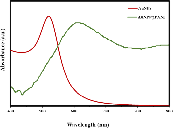
UV–vis spectra of the LSPR peak position of AuNPs and AuNPs@PANI.
FT-IR measurements (Fig. 3) provide chemical structural information, surface functionalization, and confirmation of the interaction between the AuNPs and citrate ions. The structure of the citrate ion molecule has three groups of carboxylates (COO−). The vibration modes of (COO−) confirm citrate ion adsorption on AuNPs. The characteristic peaks of (COO−), asymmetric and symmetric, appeared respectively at1617 and 1401 cm−1 (COO− stretching). In addition, FT-IR spectra have an O–H stretching peak at 3395 (broad). At low frequencies regions, have (C–O stretching) of 1265 cm−1 and 1079 cm−1 (Wulandari et al., 2015; Mohan et al., 2013). The FT-IR spectrum shows a significant change in the position of the peaks after coating the AuNPs with a layer of PANI. The vibrational bands observed for the resultant compound can be reasonably explained on the basis of the basic structure of PANI. The absorption peak is at 3395 and 3238 cm−1 (N–H stretching). The peaks are at 2923 and 2854 cm−1 (aromatic C–H stretching). Additionally, two distinct bands appear in the FT-IR spectrum, one at 1571 cm−1 representing C = C stretching on the quinoid ring in PANI and the other at 1498 cm−1 representing C = C stretching on the benzenoid ring. The peak at 1294 cm−1 corresponds to the CN stretching. A band shows up at around 1075 cm−1 for PANI and can be characterized as a vibrational mode structure of the (–NH+=), indicating the PANI chain has positive charges and a distribution of structure between benzenoid rings and quinone ring, in agreement with PANI spectrum as in Figure S2 (Mondal et al., 2014; Mallick et al., 2006; Aboelkheir et al., 2022; Yi et al., 2024; Dong et al., 2007; Abdelghany et al., 2021).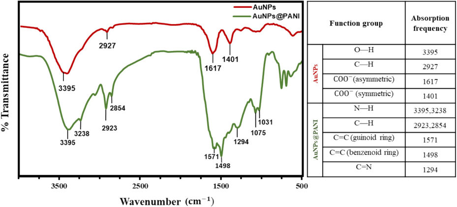
The FTIR spectra of AuNPs and AuNPS@PANI.
The morphology of the resultant nanoparticles AuNPs@PANI at the optimum synthesis (80 mM, Cu (OAC)2 and 2 M, glucose) was characterized by different techniques. Transmission electron microscope (TEM) images (Fig. 4 a and b) show AuNPs before and after the PANI coating, which clearly display the nanosphere shapes of AuNPs and the shell of the PANI polymer around the surface of AuNPs, with average size of 20 nm. The AuNPs@PANI surface was studied using scanning electron microscopy (SEM) (Fig. 4c), where it showed the spherical shape of the PANI shell, which supports the results obtained in TEM images. Fig. 4d shows the statistical diameters and the distribution of the particles depending on TEM images of the AuNPs.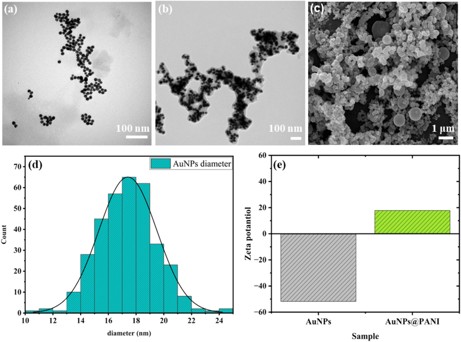
The TEM image for (a) AuNPs, and (b) AuNPs@PANI. (c) SEM image for AuNPs@PANI. (d) The statistic diameters based on TEM images of AuNPs. (e) Show Zeta potential for AuNPs and AuNPs@PANI core/shell.
The surface charge of the prepared nanoparticles was confirmed by dynamic light scattering and Zeta potential analysis. (Fig. 4e) shows that AuNPs@PANI exhibit positive zeta potential. However, an increase in zeta-potentials from −51.8 mV for AuNPs to 17.8 mV for AuNPs@PANI indicates a shift to a more positive surface potential when coating the surface with PANI.
The chemical composition of the core/shell was found by energy-dispersive X-ray analysis (EDX). The SEM-EDX spectra show the electron microscope mapping analysis of the AuNPs@PANI (Fig. 5), which showed a good distribution of Au, Cu, N, C, and O elements in the spectrum. The percentage of elements confirms the presence of core/shell structure through the presence of carbon (43.07 %), oxygen (24.37 %), and copper (17.71 %). Along with TEM images, EDX results indicates the formation of polymer chains on the surfaces. The lower percentage of gold (8.61 %) indicates its presence in the core.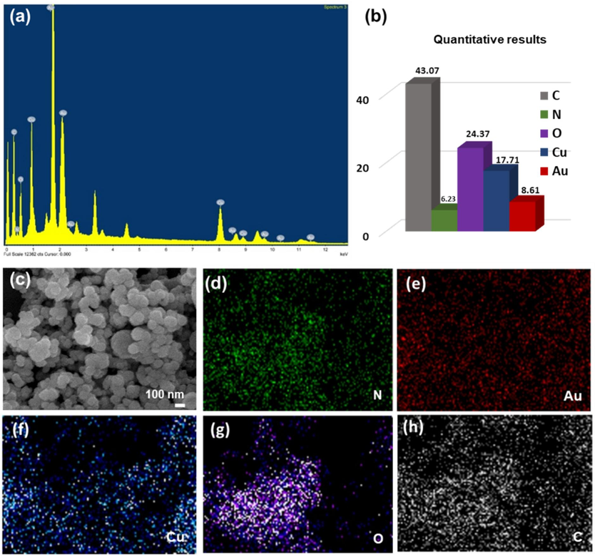
(a) EDX pattern, (b) The percentage of elements, SEM-EDX element mappings image (d) N, (e) Au, (f) Cu, (g) O, and (h) C of AuNPs@PANI core/ shell.
3.3 Fibrin degradation
The polymerization of fibrin initiates upon contact of the thrombin enzyme with the fibrinogen, which leads to the formation of a fibrin clot network. The fibrin polymerization takes place in several steps: (1) The thrombin enzyme solution works to release the fibrinopeptides from the fibrinogen, which leads to the formation of the fibrin monomer. (2) Through knob-hole interactions, the fibrin monomer self-assembled and formed a fibrin polymer (Weisel and Litvinov, 2013). Therefore, the thrombin and fibrinogen solutions in the laboratory were prepared separately using HBS buffer at pH 7.3, after that, thrombin enzyme was mixed with fibrinogen solution to prepare the clot. With the passage of time, it began to form a gel-like phase which indicates the formation of the fibrin clot network, and the clot was left at room temperature for an hour to ensure its complete formation. The effect of the prepared AuNPs and AuNPs@PANI solutions was studied by placing them in an outer layer over the network fibrin. After that, one of the samples was subjected to photolysis, and the other was placed in the dark at room temperature. Then, the modified fibrin clot was separated from the tube after completion of the reaction. Fig. 6 illustrates the protocol used to study the effect of the prepared nanoparticles on the fibrin clot.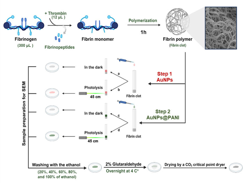
Illustrates the protocol used to study the effect of the prepared nanoparticles core/shell on the fibrin clot.
SEM images were used to verify the collapse of fibrin framework. The effect of adding a nanoparticle solution on the morphology of the formed fibrin network was studied by SEM on several spots. The change in the morphology of the fibrin polymer can be tracked by the formation of gabs on the surface. The appearance of gaps or an increase in the number of gaps, and the appearance of a fibril terminus is an indicating of degradation in the fibrin clots.
The first set of samples (Fig. 6, step 1) shows AuNPs added to fibrin clot under two conditions: (a) photolysis and (b) in dark, as shown in SEM Fig. 7. When comparing the sample of fibrin network in the dark (Fig. 7a) with the sample (Fig. 7b) under photolysis conditions by laser light at λ = 520 nm in the interface area between the clot and the AuNPs solution at room temperature for 1.5 h, the photolysis of the sample has very little effect on the fiber clot, which includes the appearance of some clusters in the fibrin network. That may be due to the absence of a strong bond between the AuNPs before coating with PANI polymer and fibrin.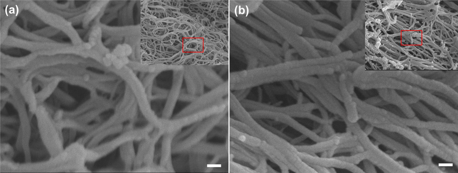
SEM images of the fibrin network morphologies after placing the AuNPs: (a) represent the dark control, and (b) represent the fibrin clot after photolysis by laser light at λ = 520 nm. Scale bar 100 nm. (onset show low magnification for large area of fibrin).
On the other hand, the other set of samples (Fig. 6, step 2) showing the effect of adding the AuNPs@PANI to fibrin. The characteristic strong blackish green color of AuNPs@PANI solution allows their penetration into the fibrin network to be monitored visually, where it leads to a clearly visible change in the color of the clot after the photolysis. When the sample was photoionized, there were clear differences in the structure of the SEM images. Severe morphological degradation sustained by the fibrin network structure (Fig. 8 a). In the dark control, no significant change was observed in the network shape, (Fig. 8 b). This result is very comparable to the shape of the fibrin network after adding AuNPs before coating with the PANI layer (Fig. 7 a and b) with the same approach.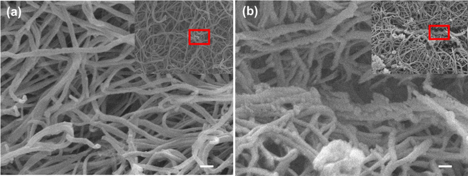
SEM images of the fibrin network morphologies after placing the AuNPs@PANI: (a) represent the dark control, and (b) represent the fibrin clot after photolysis with different magnifications. Scale bar 100 nm. (onset show high magnification for large area of fibrin).
The obtained results can be interpreted from several angles. First, the effectiveness of irradiation at 520 nm in the interface between the solution of the AuNPs coated with PANI polymer and the fibrin clot. As shown in SEM images the change in the morphology of the network is significant (Fig. 8 b). We were able to achieve fibrin degradation by photolysis AuNPs@PANI using the green laser (λ = 520 nm, 1:30 h) (Alshammari et al., 2020). Our approach offers more specific laser light and less time for degradation comparing to previous studies used 6 h and broad band light (Walker and Zaleski, 2014).
Additionally, the appearance of gaps and fibrous endings indicates the beginning of the degradation of the fibrin network in different sites of the clot. Second, According to zeta potential results, the surface PANI has a positive charge (17.8 mV) of AuNPs@PANI (Fig. 4e). This may lead to a bonding between the chain in fibrin and the AuNPs@PANI as a result of the electrostatic interactions between the positive charge in the PANI and the negative charge in the chain in fibrin newtwork (Kattula et al., 2017; Alshammari et al., 2020). Also, the thermal effects of AuNPs can impact the formed fibrin polymer. The fibrin clots were irradiated after adding the AuNPs@PANI by using an external source of laser light at 520 nm with high photothermal conversion efficiencies to heat. As a result, there is a temperature difference between the biological medium and the hot surface of AuNPs, which can cause an abrupt local hyperthermia and has an effect on fibrin clots (Hou et al., 2015). Significantly, the resonance wavelength makes the AuNPs able to efficiently absorb radiation, which leads to degradation and melting in different positions of the fibrin clots. In addition, the shells of PANI and Cu2O induce the production of electrons, which stimulate the formation of reactive oxygen species (ROS). In the presence of laser light irradiation and O2, the interaction of 1O2 with the fibrin network could be responsible for the degeneration and formation of gaps in clots. (Alshammari et al., 2020).
3.4 Statistical analysis of fibrin degradation
Quantitative analysis of fibrin degradation would support the SEM images. We applied this analysis for deeper evaluation of the gap formation on fibrin network. ImageJ software was used to process the SEM microscopy image of the fibrin network to measure the gaps at three different SEM images per sample and calculate the average area by using the threshold feature (Hartig, 2013). Fig. 9 shows the threshold image of the fibrin clot network and the drawing gap area reconstructed from the SEM image after adding the AuNPs solution under green laser light at 520 nm and a control sample in the dark. For AuNPs, the area of the holes in the dark control and photolysis were 11.9 % and 14.2 %, respectively. On the other hand, the same method was used to calculate the internal gaps between the fibers of the fibrin network after adding the prepared AuNPs@PANI. As shown in Fig. 10, the area of gaps were 10.1 % (dark control) and 30.0 % (photolysis). Specifically, when comparing the statistical analysis results (as in Table 1), the fibrin clot network after the photolysis of AuNPs@PANI had the highest gap area, which was 30.0 %. The distribution histograms give an overview of the area of all gaps and the detailed distribution of the gaps smaller than 100 nm (Fig. 11).
Gap analysis of the SEM image by ImageJ software of the fibrin clot network after adding AuNPs. The SEM image of the fibrin clot (a) in the dark; (d) after photolysis; (b, e) the threshold images reconstructed from the SEM images above; and (c, f) represent the drawing gap area of each image above, respectively. Scale bar 1
m.
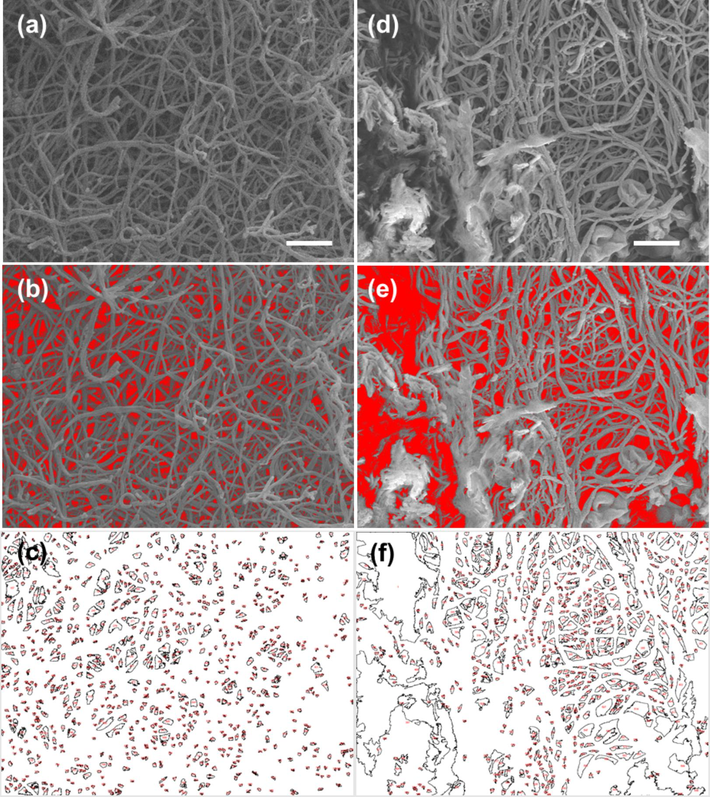
Gap analysis of the SEM image by ImageJ software of the fibrin clot network after adding AuNPs@PANI. The SEM image of the fibrin clot (a) in the dark; (d) after photolysis; (b, e) the threshold images reconstructed from the SEM images above; and (c, f) represent the drawing gap area of each image above, respectively.
Sample
Image
Total area (μm2)
Total gap (μm2)
Gap > 100 (nm2)
Count
Area %
Area
Count
Area %
AuNPs
(Dark)
Fig. 9c
47.721
663
11.894
5.676
3
1.71
AuNPs
(Photolysis)
Fig. 9f
47.728
677
14.197
6.776
8
2.29
AuNPs@PANI
(Dark)
Fig. 10c
47.848
833
10.111
4.838
0
0
AuNPs@PANI
(Photolysis)
Fig. 10f
47.726
658
29.994
14.315
9
14.74
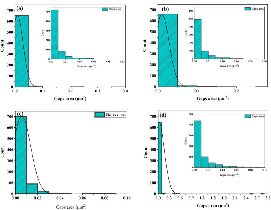
The gap area and area distribution histograms were measured from the SEM images via analysis of a sample image by ImageJ software (a) AuNPs (Dark),(b) AuNPs (photolysis), (c) AuNPs@PANI (Dark), and AuNPs@PANI (photolysis).
Additionally, Figures S3 and S4 show the threshold image reconstructed from the SEM image in another different image after adding the AuNPs, where the average value of the gap was 10.402 % (control sample) and 14.838 % (photolysis), as shown in Table S1, which shows a slight increase in the percentage of gaps formed after the photolysis. Figures S5 and S6 show the threshold image reconstructed from the SEM image in another position after adding the AuNPs@PANI solution. When comparing the statistical analysis results as shown in Table S1, the average value of the gaps larger than 100 nm after adding the AuNPs@PANI under photolysis of fibrin clots was 40.803 %. In other words, the average percentage area value of total gapes was ∼ 30.218 %, of which 12.330 % have holes that have an area larger than 100 nm. In contrast, the area percentage of the gaps larger than 100 nm of the control sample AuNPs@PANI (in the dark) were ∼ 4.86 % (meaning ∼ 10.872 % represent total gapes, of which 0.529 % of holes had an area larger than 100 nm). These statistical results clearly show the effect of the photolysis of the sample after adding the AuNPs coated with PANI, which led to a clear increase in the area ratio of the gaps. The reason for the increase in the area of the gaps and the degradation of the fibrin network in some areas is probably due only to the fact that the AuNPs@PANI core/shell structure was placed above the fibrin clot.
Potential future applications of this methodology should focus on the fact that remodeling and changing of the fibrin network could have utility to effect perfusion through the clot network, which increases the probability of the arrival of therapeutics (e.g., tPA) inside the clot (Walker and Zaleski, 2014). Furthermore, treatments may bind to the surfaces of AuNPs, due to the fact that AuNPs have emerged as nanocarriers in the biomedical domain and are diversely used in drug delivery and photo-irradiation-based therapy. Despite the fact that drugs cannot be entrapped within inorganic particles, several studies have undertaken to bind treatments to the surfaces of AuNPs due to their large surface area-to-volume ratio and bioinertness. Chemotherapeutics and photodynamic medicines have therefore been immobilized on AuNPs for disease targeting and therapy in vivo (Mao et al., 2020). Photoactivation of AuNPs coated with PANI could be achieved by using external irradiation, which should match the surface plasmon resonance localized on the nanoparticles and excitation wavelengths with appropriate penetration depth (Walker and Zaleski, 2014).
4 Conclusion
In summary, we demonstrated the effect of the prepared AuNPs@PANI core/shell on the formed fibrin network. The core/shell nanoparticles were synthesized in two steps: First, AuNPs with spherical morphology were synthesized by using trisodium citrate as a reduction agent, followed by coating the AuNPs core with PANI shell via the hydrothermal method in the presence of glucose and copper (II) acetate. The conformation was made by characterization and elemental mapping. The PANI plays an important role in this system, including: the PANI shell enhances the stability of AuNPs core; also, the surface of the PANI shell has positive charges, leading to electrostatic interactions with fibrin clots that have negatively charged surfaces. The synthesized AuNPs@PANI core/shell showed good efficiency for degradation of fibrin networks under irradiation within 1:30 h by an external source of laser light, which is a result of AuNPs' ability to absorb light at 520 nm. A scanning electron microscope (SEM) for a fibrin clot showed a clear change in the shape of the network, and the appearance of fibrous endings and gaping indicates the beginning of the degradation and melting of the fibrin network in different sites of the clot. Quantitatively, the statistical analysis results show the average value of the gaps larger than 100 nm after adding the AuNPs@PANI under photolysis of fibrin clots was 40.803 %. These statistical results clearly show the effect of the photolysis of the sample after adding the AuNPs coated with PANI, which led to a clear increase in the area ratio of the gaps. Pragmatically, future directions should focus on the fact that changing and remodeling of the fibrin clot network could have utility to effect perfusion through the clot network, which increases the probability of the arrival of therapeutics (e.g., tPA) inside the clot. Also, AuNPs have emerged as nanocarriers in the biomedical domain and are diversely used in drug delivery and photo-irradiation-based therapy; thus, thrombolytics drugs can bind to the surfaces of AuNPs. Additionally, photoactivation could be achieved by using external irradiation, which must match the nanoparticle-localized surface plasmon resonance of the nanoparticles and excitation wavelengths with appropriate penetration depth. This strategy may pave the way for innovative in vivo future applications for treating fibrin biopolymer clotting diseases.
CRediT authorship contribution statement
Riyadh H. Alshammari: Writing – review & editing, Visualization, Validation, Supervision, Software, Resources, Project administration, Methodology, Formal analysis. Abeer M. Almusaad: Writing – original draft, Investigation, Funding acquisition, Data curation. Tahani S. Algarni: Writing – review & editing, Validation, Supervision, Resources.
Acknowledgments
The authors thanks Researchers Supporting Project (Ref: RSP2024R442), King Saud University, Riyadh, Saudi Arabia.
Declaration of competing interest
The authors declare that they have no known competing financial interests or personal relationships that could have appeared to influence the work reported in this paper.
References
- Structural, optical, and electrical reinforcement of gamma-irradiated PEO/SA/Au NPs nanocomposite. J. Mater. Sci. Mater. Electron.. 2021;32(5):6538-6549.
- [Google Scholar]
- Synthesis and characterization of the thin films containing polyaniline-carboxymethyl cellulose composites. Egypt. J. Chem.. 2022;65(1):335-340.
- [Google Scholar]
- Au-Cu@ PANI alloy core shells for aerobic fibrin degradation under visible light exposure. ACS Appl. Bio Mater.. 2020;3(11):7631-7638.
- [Google Scholar]
- A review on polyaniline composites: synthesis, characterization, and applications. Polym. Compos.. 2021;42(7):3142-3157.
- [Google Scholar]
- Interfacial synthesis of gold-polyaniline nanocomposite and its electrocatalytic application. ACS Appl. Mater. Interfaces. 2015;7(51):28393-28403.
- [Google Scholar]
- A novel approach to the construction of core-shell gold–polyaniline nanoparticles. Nanotechnology. 2007;18(45):455603
- [Google Scholar]
- Synthesis and evaluation of doxorubicin-loaded gold nanoparticles for tumor-targeted drug delivery. Bioconjug Chem. 2018;29(2):420-430.
- [Google Scholar]
- Water-soluble gold/polyaniline core/shell nanocomposite: synthesis and characterization. Synth. Met.. 2014;195:23-28.
- [Google Scholar]
- Silica shell growth on vitreophobic gold nanoparticles probed by plasmon resonance dynamics. J. Phys. Chem. C. 2021;125(45):25119-25125.
- [Google Scholar]
- Effect of electrospinning parameters on morphology of polydioxanone nanofibers. Mater. Res. Express. 2019;6(12):125330
- [Google Scholar]
- Rapid and template-free synthesis of Cu2O truncated octahedra using glucose as green reducing agent. Mater. Lett.. 2018;210:31-34.
- [Google Scholar]
- Basic image analysis and manipulation in ImageJ. Curr. Protocols Mol. Biol.. 2013;102(1):14-15.
- [Google Scholar]
- Fine-tuning the LSPR response of gold nanorod-polyaniline core–shell nanoparticles with high photothermal efficiency for cancer cell ablation. J. Mater. Chem. B. 2015;3(26):5189-5196.
- [Google Scholar]
- Synthesis of gold nanoparticles/polyaniline boronic acid/sodium alginate aqueous nanocomposite based on chemical oxidative polymerization for biological applications. Int. J. Biol. Macromol.. 2021;179:196-205.
- [Google Scholar]
- Copper-catalyzed aerobic oxygenative cross dehydrogenative coupling of methyl ketones with para-C–H of primary anilines. Green Chem.. 2017;19(3):619-622.
- [Google Scholar]
- Assessment of effects of laser light combining three wavelengths (450, 520 and 640 Nm) on temperature increase and depth of tissue lesions in an ex vivo study. Materials. 2020;13(23):5340.
- [Google Scholar]
- Fibrinogen and fibrin in hemostasis and thrombosis. Arterioscler. Thromb. Vasc. Biol.. 2017;37(3):e13-e21.
- [Google Scholar]
- Core@ shell nanoparticles: greener synthesis using natural plant products. Appl. Sci.. 2018;8(3):411.
- [Google Scholar]
- A straightforward route to tetrachloroauric acid from gold metal and molecular chlorine for nanoparticle synthesis. Metals. 2015;5(3):1454-1461.
- [Google Scholar]
- Effect of iron oxide nanoparticles on fibrin gel formation and its fractal dimension. J. Chem. Phys.. 2019;150(15):155103
- [Google Scholar]
- Unique roles of gold nanoparticles in drug delivery, targeting and imaging applications. Molecules. 2017;22(9):1445.
- [Google Scholar]
- One-step synthesis of monodisperse AuNPs@ PANI composite nanospheres as recyclable catalysts for 4-nitrophenol reduction. J. Nanopart. Res.. 2016;18:1-11.
- [Google Scholar]
- Fibrin gel as an injectable biodegradable scaffold and cell carrier for tissue engineering. Scientific World J.. 2015;2015(1):685690
- [Google Scholar]
- Macroscopic Au@ PANI core/shell nanoparticle superlattice monolayer film with dual-responsive plasmonic switches. ACS Appl. Mater. Interfaces. 2020;12(9):11296-11304.
- [Google Scholar]
- Gold nanoparticles: synthesis, physiochemical properties and therapeutic applications in cancer. Drug Discov. Today. 2021;26(5):1284-1292.
- [Google Scholar]
- Polymerization of aniline by cupric sulfate: a facile synthetic route for producing polyaniline. J. Polym. Res.. 2006;13:397-401.
- [Google Scholar]
- Gold nanospheres and nanorods for anti-cancer therapy: comparative studies of fabrication, surface-decoration, and anti-cancer treatments. Nanoscale. 2020;12(28):14996-15020.
- [Google Scholar]
- Functionalised gold nanoparticles for selective induction of in vitro apoptosis among human cancer cell lines. J. Exp. Nanosci.. 2013;8(1):32-45.
- [Google Scholar]
- Water soluble gold-polyaniline nanocomposite: a substrate for surface enhanced raman scattering and catalyst for dye degradation. Arab. J. Chem.. 2020;13(2):4009-4018.
- [Google Scholar]
- One pot green synthesis of polyaniline coated gold nanorods and its applications. RSC Adv.. 2014;4(100):57282-57289.
- [Google Scholar]
- Micro/nano-fibrillated cellulose (MFC/NFC) fibers as an additive to maximize eucalyptus fibers on tissue paper production. Cellul.. 2021;28(10):6587-6605.
- [Google Scholar]
- A review of fibrin and fibrin composites for bone tissue engineering. Int. J. Nanomed.. 2017;12:4937.
- [Google Scholar]
- Influence of the sequence of the reagents addition in the citrate-mediated synthesis of gold nanoparticles. J. Phys. Chem. C. 2011;115(32):15752-15757.
- [Google Scholar]
- Localized surface plasmon resonance: nanostructures, bioassays and biosensing–a review. Anal. Chim. Acta. 2011;706(1):8-24.
- [Google Scholar]
- Nanomaterials: classification, properties, and environmental toxicities. Environ. Technol. Innov.. 2020;20:101067
- [Google Scholar]
- Gold nanoparticles for drug delivery and cancer therapy. Appl. Sci.. 2020;10(11):3824.
- [Google Scholar]
- Monodisperse Sub-10 Nm gold nanoparticles by reversing the order of addition in Turkevich method-the role of chloroauric acid. J. Colloid Interface Sci.. 2011;361(2):543-547.
- [Google Scholar]
- Effects of 445 Nm, 520 Nm, and 638 Nm laser irradiation on the dermal cells. Int. J. Mol. Sci.. 2021;22(21):11605.
- [Google Scholar]
- Nano-Au@ PANI core-shell nanoparticles via in-situ polymerization as electrode for supercapacitor. J. Alloy. Compd.. 2017;722:1-7.
- [Google Scholar]
- A study of the nucleation and growth processes in the synthesis of colloidal gold. Discuss. Faraday Soc.. 1951;11:55-75.
- [Google Scholar]
- Fibrin (Ogen) in human disease: both friend and foe. Haematologica. 2020;105(2):284.
- [Google Scholar]
- Photothermal plasmonic triggering of Au nanoparticle surface radical polymerization. Chem. Mater.. 2011;23(23):5275-5281.
- [Google Scholar]
- Non-enzymatic remodeling of fibrin biopolymers via photothermally triggered radical-generating nanoparticles. Chem. Mater.. 2014;26(17):5120-5130.
- [Google Scholar]
- Emerging advances in nanomedicine with engineered gold nanostructures. Nanoscale. 2014;6(5):2502-2530.
- [Google Scholar]
- Mechanisms of fibrin polymerization and clinical implications. Blood J. Am. Soc. Hematol.. 2013;121(10):1712-1719.
- [Google Scholar]
- Fibrin formation, structure and properties. Fibrous Proteins: Struct. Mech. 2017:405-456.
- [Google Scholar]
- Characterization of citrates on gold and silver nanoparticles. J. Colloid Interface Sci.. 2015;438:244-248.
- [Google Scholar]
- Gold nanoparticle based photothermal therapy: development and application for effective cancer treatment. Sustain. Mater. Technol.. 2019;22:e00109.
- [Google Scholar]
- Conventional and microwave hydrothermal synthesis and application of functional materials: a review. Materials. 2019;12(7):1177.
- [Google Scholar]
- Toward coupling across inorganic/organic hybrid interfaces: polyaniline-coated gold nanoparticles with 4-aminothiophenol as gold-anchoring moieties. Colloid Polym. Sci. 2024:1-9.
- [Google Scholar]
- Temperature-dependent cell death patterns induced by functionalized gold nanoparticle photothermal therapy in melanoma cells. Sci. Rep.. 2018;8(1):1-9.
- [Google Scholar]
- Biomimetic fibrin-targeted and H2O2-responsive nanocarriers for thrombus therapy. Nano Today. 2020;35:100986
- [Google Scholar]
Appendix A
Supplementary data
Supplementary data to this article can be found online at https://doi.org/10.1016/j.arabjc.2024.105948.
Appendix A
Supplementary data
The following are the Supplementary data to this article:Supplementary Data 1
Supplementary Data 1


