

Translate this page into:
Growth and physico-chemical properties of interconnected carbon nanotubes in FeSBA-15 mesoporous molecular sieves
⁎Corresponding author. Tel.: +61 7 3346 4122; fax: +61 7 3346 3973. a.vinu@uq.edu.au (Ajayan Vinu)
-
Received: ,
Accepted: ,
This article was originally published by Elsevier and was migrated to Scientific Scholar after the change of Publisher.
Peer review under responsibility of King Saud University.
Abstract
Carbon nanotubes (CNTs) with well-defined hollow interiors, and different morphologies have been grown inside the nanochannels of iron substituted SBA-15 (Santa Barbara Amorphous) with different iron contents and well-ordered large mesopores by chemical vapour deposition method. This novel method requires only 3 min for the formation of high quality multiwalled CNTs inside the SBA-15. The physico-chemical characteristics of the prepared CNT/Fe-SBA-15 nanocomposite have been analysed with powder X-ray diffraction (XRD), scanning electron microscopy (SEM), Raman spectroscopy and thermogravimetric analysis (TGA). XRD, Raman spectroscopy and TGA results confirm that the formed CNTs in SBA-15 nanochannels are highly pure and graphitic in nature, which can be altered by tuning the Fe content in the support matrix. SEM images show the interconnected network of SBA-15/CNT where CNT bridges the neighbouring SBA-15 nanoparticles. Interestingly, spring like CNTs and multi-terminal junctions such as Y and H junctions were also observed. The morphology of the CNTs inside the nanochannels of the SBA-15 support can also be controlled by the simple adjustment of the iron content in the SBA-15 framework. It has also been found that the content of Fe in the silica framework of SBA-15 plays a significant role in the formation of the CNTs and the amount of deposited CNTs in the nanochannels of SBA-15 increased with increasing the concentration of iron in framework. Among the materials studied, the FeSBA-15 with the nSi/nFe ratio of 2 showed the highest catalytic activity towards the formation of high quality CNTs.
Keywords
SBA-15
Nanoporous
Mesoporous
Carbon nanotube
Catalytic growth

1 Introduction
Mesoporous materials with regular geometries have been paid much attention because of their unique characteristics such as uniform pore size, sustainable physicochemical stability and large surface area (Sayari, 1996; Beck et al., 1992; Zhao et al., 1998a,b). Among many nanosized templates, SBA-15 is one of the most attractive materials owing to its large surface area, well-ordered porous structure, and strong and thick walls, which provide a high mechanical stiffness and hydrothermal stability (Kresge et al., 1992; Zhao et al., 1998a,b). Because of these qualities, SBA-15 has been widely used for different applications including catalysis, adsorption, separation, sensing, medical usage, ecology, and nanotechnology (Raman et al., 1996; Davis, 2002; Vinu et al., 2003, 2008; Miyahara et al., 2006). However, mesoporous silica SBA-15 is insulative in nature which limits its application in nanoelectronics. Carbon nanotubes (CNTs) are fascinating materials (Dresselhaus et al., 1996; Pan et al., 1999) as they have unique optical, electrical and mechanical properties which make them attractive for many potential applications in nanoelectronics, energy storage, and sensing (Ijima, 1991; Ajayan and Zhou, 2001; Dai, 2002; Hirsch and Vostrowsky, 2005; Kuzmany et al., 2004). However, the limited surface area of bulk CNTs makes hurdles for their use in applications such as adsorption and separation, and catalysis. By coupling the high surface area and well-ordered porous structure of SBA-15 with CNTs, many application possibilities could emerge: from catalysis to the adsorption of various toxic molecules to energy storage. In addition, the SBA-15 can offer well-ordered porous platform which can offer enough control over the growth, shape, morphology and the orientation of the CNTs.
Various methods are available for the synthesis of both multiwalled CNTs and single walled CNTs including electric arc discharge (Ando and Iijima, 1993), laser ablation (Guo et al., 1995), and chemical vapour deposition (CVD) (Ivanov et al., 1994). Among the different methods of nanotube production, CVD route which uses the catalysts and light hydrocarbon gases for the growth of the CNTs seems to be the most promising for large scale industrial applications, stemming from the relatively easy opportunity to upscale both the preparation and purification methods. CVD method also offers any sort of in-situ controls over position and orientation (Zheng et al., 2002; Zhang et al., 2001a,b; Li et al., 1996, 1999; Cassell et al., 1999, 2001; Zhu et al., 2002; Joselevich and Lieber, 2002). The orientation of nanotubes could arise from template assembly (Zheng et al., 2002; Zhang et al., 2001a; Li et al., 1996, 1999; Cassell et al., 2001) with van der Waals interaction between nanotube themselves, nanotubes and template (Zhu et al., 2002; Cassell et al., 1999), and from external electric fields (Joselevich and Lieber, 2002; Zhang et al., 2001b). Researchers have already tried to use the porous templates including anodic alumina, zeolites, and mesoporous silica for controlling the orientation and the morphology of the CNTs (Ying et al., 1999; Ivanov et al., 1995; Mukhopadhyay et al., 1999; Laurent et al., 1998; Flahaut et al., 1999; Xie et al., 2000a,b; Cassell et al., 1999). In the case of anodic alumina, CNTs of low degree of graphitization can be deposited in its mesopores by pyrolysis of hydrocarbon (Ying et al., 1999) and alumina acts as catalyst for the growth of CNTs. In addition, CNTs are confined inside the nanochannels and get the pore dimension of the alumina template. On the other hand, mesoporous silicas are neutral in charge and cannot catalyse the growth of the CNTs inside the channels. It is required that the nanochannels of the porous silica template should be decorated with transition metal catalysts for the growth of CNTs inside the pores (Vinu and Hartmann, 2004; Karthik et al., 2004a,b; Hartmann et al., 2002; Vinu et al., 2002). It should be noted however, that the template function of porous silica depends on the pore structure and distribution of transition metals along the porous channels. By realizing this opportunity, several researchers tried to incorporate transition metal ions in the porous silica or aluminosilicate supports and used them for the growth of CNTs (Li et al., 1996; Xie et al., 2000a,b; Zhang et al., 2001a).
Ivanov et al. (1995) and Mukhopadhyay et al. (1999) reported the production of multiwalled carbon nanotubes (MWNTs) with 3–8 nm inner, 5–25 nm outer diameters and up to 60–100 μm length with remarkable efficiency at low temperature using the metal substituted zeolite support. Laurent et al. (1998) and Flahaut et al. (1999) have also reported on the synthesis of mixtures of single walled nanotubes (SWNTs) and MWNTs at about 1270–1370 K on Fe–Al2O3 and on Al2O3–Mg containing spinel type composite materials in 2–7% yield. Li and co-workers reported the growth of CNTs on mesoporous silica (Li et al., 1996) and films (Xie et al., 2000a,b) embedded with iron nanoparticles. Cassell et al. (1999) tested CNT growth on mesoporous silica-alumina films with different transition metal concentration (Fe, Co and Ni) while Zhang et al. (2001a) successfully prepared CNT pattern on 3D cubic mesoporous silica thin films by soft lithography. Although several reports are available on formation of MWNTs on template, still fundamental question such as the nature of interaction between the support and the metal particles is unresolved. In addition, the post-synthetically prepared metal substituted porous support system with smaller pores were mainly used for the growth of CNTs. However, this would allow the growth of the CNTs mostly on the external surface of the porous support system due to the smaller pores and the presence of metal or metal oxide catalysts on the external surface. Therefore, it is important to use the porous support with the large pore for the growth of the CNTs inside the porous channels and make use of the shape and size of the pores to control the diameter of the CNTs. However, the reports on the use of mesoporous support with large pore for making the nanocomposites are quite limited. In this work, we report on the growth of CNTs with different morphology over directly synthesized large pore mesoporous ferrosilicate (FeSBA-15) with different iron contents and ordered porous structure. Our primary focus here is not only to prepare the CNT/FeSBA-15 nanocomposites with different iron contents but also with different forms of CNTs as they can be utilized for various applications that require peculiar properties (Konya et al., 2005; Kukovecz et al., 2005; Pang et al., 2004; Aguado-Serrano et al., 2004; Smith et al., 1995; Vaitchev et al., 1997). The prepared CNTs/FeSBA-15 nanocomposites have been characterized by various sophisticated techniques in order to understand the structure and properties of the grown CNTs inside the nanochannels. It has been found that the amount of Fe in the FeSBA-15 plays a significant role not only in controlling the morphology and the type of CNTs but also the quantity of the CNTs.
2 Materials and methods
FeSBA-15 materials with various nSi/nFe ratio were prepared under acidic condition by using triblock copolymer poly (ethylene glycol)-block-poly-(propylene glycol)-block-poly (ethylene glycol) (Pluronic P123, molecular weight = 5800, EO20PO70EO20) as structure directing agent (Vinu et al., 2005). In a typical synthesis, amphiphilic triblock copolymer Pluronic P123 (4 g) was dispersed in 30 g of water and stirred for 4 h at room temperature. Then 70 ml of 0.29 M HCl was added and the mixture was stirred for 2 h at 40 °C. Then, 9 g of tetraethyl orthosilicate (TEOS) and the appropriate amount of ferric nitrate were added directly to the homogenous solution with stirring. The resulting gel was aged at 40 °C for 24 h and finally heated at 100 °C for 48 h. The samples were labelled FeSBA-15(x) where x denotes the nSi/nFe molar ratio. After filtering and washing with water, the obtained solids were calcined in flowing first in nitrogen and then to air at 540 °C to decompose the triblock copolymer. Carbon deposition was carried out by using CVD method over FeSBA-15 with different nSi/nFe ratios (2, 3, 5) which act as the catalysts as well as the supports. Benzene vapour was introduced into the reaction chamber at 1000 °C only for 3 min. The iron atoms in the FeSBA-15 catalyse the growth of the CNTs inside the nanochannels and the black sample thus obtained was treated with conc. HNO3 (60%) solution for 3 h at room temperature in order to remove the amorphous carbon from the formed CNTs. Then, the product was separated by centrifugation at 10,000 rpm and washed with water and dried in air at 100 °C for 5 h to obtain the resultant FeSBA-15/CNT nanocomposite. The samples were characterized by powder X-ray diffraction (XRD) pattern collected using a Rigaku diffractometer with Cu Kα (λ = 0.154 nm) radiation. The diffractograms were recorded in the 2θ range of 10–80° with the scan rate of 1° per min. The morphology, quantity and the type of CNTs grown inside the FeSBA-15 were investigated by using Hitachi S-4800 high resolution scanning electron microscope (HRSEM). Raman spectra were recorded on Jobin Won Horiba T64000 in an ambient pressure using a He–Ne Laser (λ = 514 nm). Thermogravimetric analysis (TGA) of carbon sample was performed at a heating rate of 5 °C/min up to 800 °C in air.
3 Results and discussion
The structural information of the FeSBA-15 materials with different iron contents was first investigated by powder XRD measurements. Fig. 1 shows the low angle XRD pattern of FeSBA-15 with different nSi/nFe ratios. The relatively well-defined pattern with (1 0 0), (1 1 0) and (2 0 0) reflections has been observed and can be indexed to the hexagonal space group p6 mm. The length of the hexagonal unit cell a0 is calculated using formula a0 = 2d100/√3. The unit cell parameter of the material increases from 9.35 nm for FeSBA-15(5) to 10.61 nm for FeSBA-15(2), revealing the enlargement of the unit cell upon the incorporation of Fe atoms in the SBA-15 framework. This further suggests that Fe species are incorporated into the silica framework of SBA-15. The intensity of (1 0 0) peak decreases with increasing the Fe content in the silica framework. However, the well-defined (1 0 0) reflection together with the higher order (2 0 0) and (2 1 0) peaks are clearly visible for all the samples, suggesting that ordered mesoporous structure has been maintained even after introduction of a high amount of Fe species. To the best of our knowledge and literature survey, this is the first time that the use of FeSBA-15 with a high Fe content prepared under highly acidic medium for CNT growth in which iron has been embedded in framework instead of pores, has been tried. Generally, Fe atoms in the ferrosilicate framework inside the pores and the template effect of the pores constrain the growth of CNTs mostly along the axis of the pores but the CNTs formed over the iron or iron oxide particles on the external surface of the FeSBA-15 support may grow freely (Li et al., 1996).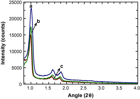
Low angle XRD patterns of FeSBA-15(x) with different nSi/nFe ratio: (a) FeSBA-15(5), (b) FeSBA-15(3), and (c) FeSBA-15(2).
In order to know the phase of the iron or iron oxide nanoparticles in the channels of the FeSBA-15, the samples were also characterized by wide angle powder XRD patterns. Fig. 2 shows the wide angle XRD patterns of the FeSBA-15(x) samples with different iron contents. No distinct diffraction peaks have been observed for the sample with nSi/nFe molar ratio 5 indicating that iron species in mesoporous silica matrix are finely dispersed on the surface of the porous channels and the particles are not agglomerated but rather in the form of ultrasmall nano-crystallites. As the ratio increases from 5 to 2, the diffraction peaks corresponding to hexagonal phase of α-Fe2O3 (JCPDS, File No. 17-0536) are appeared. The intensity of those peaks increases significantly with increasing the amount of iron. These samples are phase pure as the XRD patterns do not show any traces of other phases of Fe2O3, such as β, υ or δ or any phase of iron hydroxides, such as FeOOH or Fe (OH)3. It is interesting to note that the intensity of (1 0 4) and (1 1 0) peak is nearly same for FeSBA-15(3) whereas a strong intense (1 0 4) is observed for FeSBA-15(2), indicating a preferential orientation of α-Fe2O3 nanostructures in the porous channels and difference in the size of the nanocrystallites. From these data, it is quite clear that the samples prepared with different iron contents possess the α-Fe2O3 nanoparticles with different size that are finely dispersed along the mesochannels. The information on the particle growth and nano to microstructural formation of the α-Fe2O3 species in silica matrix is needed to identify its relation on the growth of CNT and formation of CNT/FeSBA-15 nanocomposite.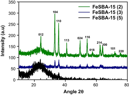
Wide angle XRD patterns of FeSBA-15(x) with different nSi/nFe ratios.
Fig. 3 shows the wide-angle XRD pattern of the as synthesized CNTs over FeSBA-15 with different nSi/nFe ratios. The samples show two diffraction peaks at 26° and 43° corresponding to the interlayer spacing of the nanotube and the d100 reflection of the graphitic carbon atoms, respectively. The turbostratic nature of the carbon atoms in the carbon nanotubes is clearly visible from the asymmetry of the band at 43°. Intensity of these peaks also shows that the samples prepared in this work are having high graphitic crystallinity. Peak at 53° is also seen for the sample which mainly corresponds to (0 0 4) reflection of the carbon atoms, further confirming the presence of graphitic porous carbon. With respect to increase in iron concentration in FeSBA-15, crystallinity of graphitic carbon increases along (1 0 0) direction with the concomitant decrease of the (0 0 2) peak. One possible explanation is that iron content influences the assembly pathways and the final form of the grown CNTs. When Fe is incorporated in the pores of SBA-15, the well-ordered pores restrict the growth of CNT along one direction. This was also evident in most of the reports as the growth of graphitic CNT along c-axis was observed. However, when Fe is incorporated into the silica porous matrix, non-restricted, free standing, random CNTs are grown from the ferrosilicate framework of FeSBA-15.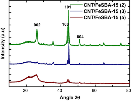
Wide angle XRD patterns of CNT/FeSBA-15(x) with different nSi/nFe ratios.
Fig. 4 shows the HRSEM images of CNT/FeSBA-15(x) nanocomposite after HNO3 treatment. All the samples exhibited a very high activity towards CNT formation. Diameter of the tube for all tried concentration of Fe varies from 100 to 125 nm. There is no correlation found when the content of the iron was varied. It has been previously reported that the thickness of CNT can be controlled by tuning the content of Fe catalyst (Zheng et al., 2002). It is generally accepted that the tubes grow by the extrusion of carbon dissolved in metallic catalyst particles that are oversaturated in carbon at one part of the surface and that the catalyst particle promotes tip growth or base growth depending on the contact force between the catalyst particles and the substrate (Li et al., 1996). These results were expected as the size of the Fe species in matrix increases with increasing the concentration and catalyst size is the main part of determining diameter of the CNTs. However, in our case, iron atoms are incorporated into the silica framework and they are not formed as single particle. Therefore, the difference in the diameter of the CNTs as a function of Fe in the FeSBA-15 support was not observed.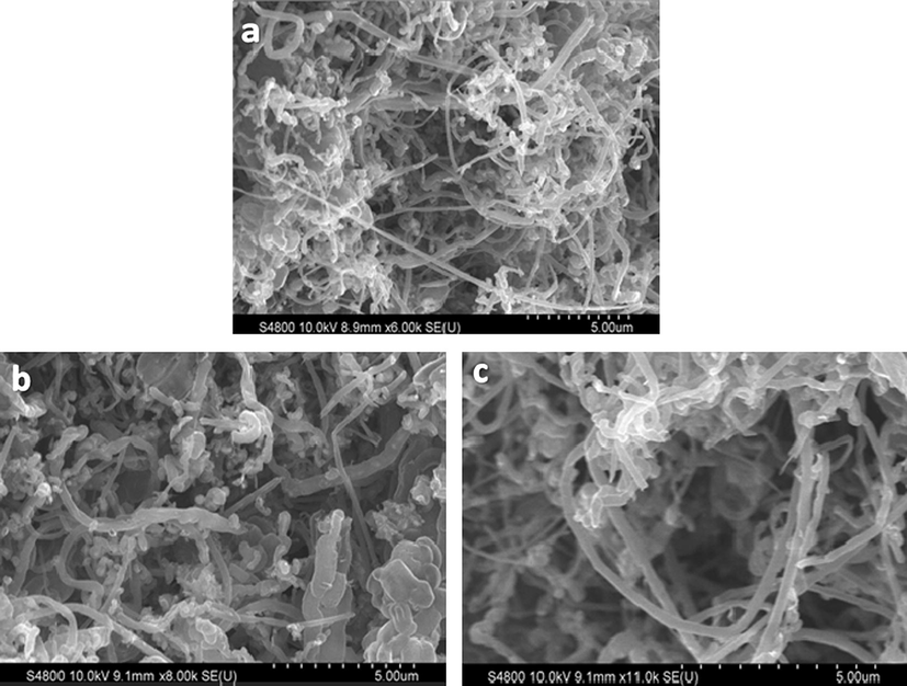
HRSEM images of CNT/FeSBA-15 with different Fe contents: (a) CNT/FeSBA-15(2), (b) CNT/FeSBA-15(3), and (c) CNT/FeSBA-15(5).
In the previous reports, the flow of precursors was also considered as the reason for the formation of CNTs with different diameter (Zheng et al., 2002). The hydrocarbon flow for longer time promotes the diffusion of precursor to the growth sites and results in higher growth rate of CNTs and better alignment with the concomitant reduction of a space between adjacent CNTs which is mainly due to the carbonaceous deposition on their side walls, thereby diminishing the supply of precursor gas to the growth sites at the base end of CNTs. However, in our case, benzene vapours have been passed in reaction chamber only for 3 min which result in CNTs of nearly same outer diameter. Therefore, the exposure of benzene vapours for 3 min at 1000 °C is sufficient for the formation of highly graphitic/conducting CNTs without much significant change in the diameter of the CNTs. It should also be noted that the diameter of the tubes (100–125 nm) observed in this study is comparatively higher than that of the other reports where catalyst particles are trapped inside the pores. As can also be seen, CNTs are also formed on the external surface of the support system. In FeSBA-15, the amount of extra framework Fe increases with increasing the Fe content in the sample. During the calcination, some of the Fe atoms come out of the framework which then catalyse the CNT growth. As Fe doping level increases, amount of extra framework of Fe is also increased. These extra framework iron or iron oxide nanoparticles are responsible for the growth of the CNTs on the external surface. However, the quantity of the formation of CNTs increased with increasing the Fe content of the FeSBA-15 matrix. In the case of FeSBA-15(2), spring like CNTs are formed whereas FeSBA-15(5) offers the CNTs with Y junction (Fig. 5).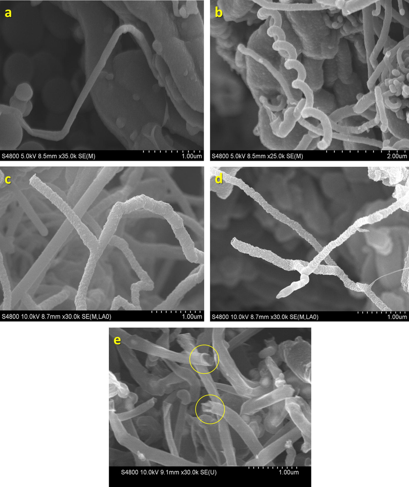
HRSEM images of CNT/FeSBA-15 with different Fe contents: (a and b) CNT/FeSBA-15(2), (c) CNT/FeSBA-15(3), (d) CNT/FeSBA-15(5), and (e) purified CNT/FeSBA-15(2).
It is also quite interesting to see that the growth of CNTs is originated from the FeSBA-15 matrix itself (Fig. 5a) and even connected with the other FeSBA-15 particles. The connectivity is enhanced with increasing the Fe content in the support (Fig. 5a). After deposition of CNTs on FeSBA-15(x), CNTs formed the interconnected network as such as in Fig. 6 which may facilitate electron transport and further increases the conductivity of the nanocomposite. As we explained previously, various morphologies such as spring like CNT (Fig. 5b), multiterminal junctions such as Y, H can be generated (Fig. 5c and d) especially Y junction by simply altering the concentration of Fe in the silica framework. These junctions are of great interest for their potential use in nanoscale CNT transistor or amplifier applications. After 3 h of treatment with a strong HNO3 and centrifugation at 10,000 rpm, the separation of CNTs from FeSBA-15 was not observed, revealing the strong bonding between the support and the formed CNTs. It is also interesting to note that the long formed CNTs can be cut down by treating the composite with conc. HNO3 acid (Fig. 5e). However, the bonding between the CNTs and FeSBA-15 was not affected by this treatment, indicating that strong mechanical bonding and the connectivity between the FeSBA-15 particles, and the CNTs are grown with the help of Fe in the ferrosilicate framework of the SBA-15, which are quite strongly bonded.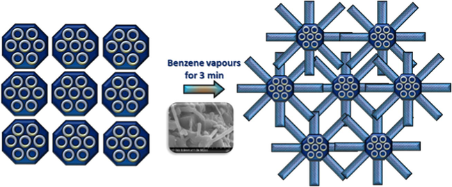
Schematic representation of the formation of CNT and FeSBA-15 interconnected network. Inset shows SEM image of interconnected network between FeSBA-15 and CNT.
The quality of the CNTs deposited on FeSBA-15(x) is indicated by Raman spectra with an excitation laser of 514 nm (see Fig. 7). Two characteristic peaks were observed, one peak, the D-band, is located at approximately 1326 cm−1 and is attributed to defects, curved graphite sheets and lattice distortion in the carbon structures. The intensity of G-band increases with the increase of iron content. This indicates that the quantity of the Fe content in the silica framework is important to control the graphitic nature of the CNTs. The G-band at about 1588 cm−1 is characteristic of graphite. The intensity ratios between D-band and G-band (ID/IG ratio) were found to be 1.32 for CNT/FeSBA-15(5), 0.423 for CNT/FeSBA-15(3) and 0.396 for CNT/FeSBA-15(2). These results reveal that CNTs with higher quality are formed when FeSBA-15(2) was used as the support and catalyst. As the longer deposition results in thickening of walls with amorphous carbon and defects, this rapid growth results in high quality carbon nanotubes within 3 min only. No radial breathing mode has been observed for all the deposited samples, indicating that all the deposited CNTs are multiwalled CNTs.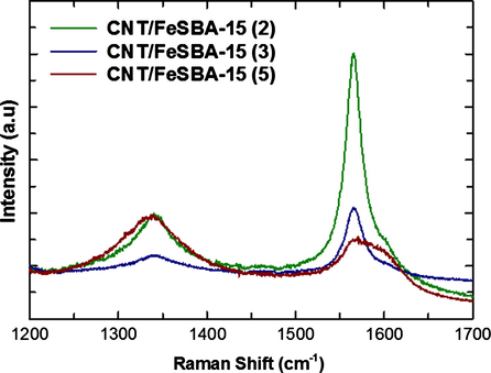
Raman spectra of FeSBA-15(x) after the deposition of CNT.
The better quality of the CNTs formed at higher loading of Fe in the silica framework of FeSBA-15 is also confirmed by TGA analysis as shown in Fig. 8. The FeSBA-15(2) gives the weight loss of only 3% between 450 and 650 °C whereas the weight loss for the CNT/FeSBA-15(5) nanocomposite is 13%. The gasification temperature is observed at 400–500 °C which indicates high quality of MWNTs with low defect densities. Inset of Fig. 8 shows TGA analysis for FeSBA-15(x) which reveals a high thermal stability up to 800 °C and weight loss is very less. For FeSBA-15(5) weight loss is 2.7% which is the highest value observed for the CNT/FeSBA-15 nanocomposite. The amount of carbon deposited on catalyst was calculated from the difference in weight of catalyst before (m0) and after (mp) treatment in the benzene flow by using following equation
The amount of synthesized CNT also increased with the increase of iron content in the framework. This was attributed to the fact that iron is playing a key role in benzene thermal decomposition and the rate of thermal decomposition in the presence of iron was faster resulting in more deposited carbon.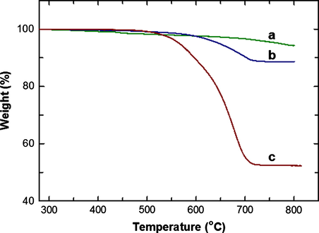
TGA of FeSBA15(x) after CNT deposition. (a) CNT/FeSBA-15(2), (b) CNT/FeSBA-15(3), and (c) CNT/FeSBA-15(5).
4 Conclusions
In conclusion, we have successfully grown CNTs inside the mesochannels of large pore FeSBA-15 with different nSi/nFe ratio where iron has been incorporated in framework by direct synthesis method instead of post-synthetic approach. The characterization results reveal that hexagonal well-ordered porous structure of SBA-15 was retained even after the incorporation of huge amount of Fe in the silica framework of SBA-15. FeSBA-15 catalyst was found to be highly active for the growth of CNTs. The quantity and the quality of the grown CNTs can be controlled by changing the amount of Fe in the silica framework of FeSBA-15 support. It has been demonstrated that FeSBA-15 with the highest Fe content provided the CNTs with highly graphitic and conductive in nature and they are strongly bonded with the FeSBA-15 support. We also demonstrated that the morphology of the grown CNTs can be controlled with the simple adjustment of the Fe in the SBA-15 framework. CNTs with spring, and Y and H type junctions were prepared by using FeSBA-15 with different iron contents. Raman analysis revealed that the prepared CNTs are highly graphitic and pure. This simple strategy of growing CNTs and the formation of the CNT/mesoporous silica nanocomposite could be extended to other metal substituted mesoporous system with different structure and morphology that would allow to prepare CNTs with tunable size and morphology.
Acknowledgements
Ajayan Vinu is grateful to ARC for the award of the future fellowship and the University of Queensland for the start-up grant. The project was also financially supported by King Saud University, Vice Deanship of Scientific Research Chairs.
References
- Silica/C composites prepared by the sol–gel method. Influence of the synthesis parameters on textural characteristics. Micropor. Mesopor. Mater.. 2004;74:111.
- [Google Scholar]
- Preparation of carbon nanotubes by arc-discharge evaporation. Jpn. J. Appl. Phys.. 1993;32:107.
- [Google Scholar]
- A new family of mesoporous molecular sieves prepared with liquid crystal templates. J. Am. Chem. Soc.. 1992;114:10834.
- [Google Scholar]
- Directed growth of free-standing single-walled carbon nanotubes. J. Am. Chem. Soc.. 1999;121:7975.
- [Google Scholar]
- Combinatorial optimization of heterogeneous catalysts used in the growth of carbon nanotubes. Langmuir. 2001;17:260.
- [Google Scholar]
- Carbon nanotubes: synthesis, integration, and properties. Acc. Chem. Res.. 2002;35:1035.
- [Google Scholar]
- Science of Fullerenes and Carbon Nanotubes. Elsevier Science, USA: Academic Press; 1996.
- Synthesis of single-walled carbon nanotubes using binary (Fe Co, Ni) alloy nanoparticles prepared in situ by the reduction of oxide solid solutions. Chem. Phys. Lett.. 1999;300(1–2):236.
- [Google Scholar]
- Catalytic growth of single-walled nanotubes by laser vaporization. Chem. Phys. Lett.. 1995;243(1–2):49.
- [Google Scholar]
- The study of carbon nanotubes produced by catalytic method. Chem. Phys. Lett.. 1994;223:329.
- [Google Scholar]
- Catalytic production and purification of nanotubes having fullerene-scale diameters. Carbon. 1995;33:1727.
- [Google Scholar]
- Vectorial growth of metallic and semiconducting single-wall carbon nanotubes. Nano Lett.. 2002;2002(2):1137.
- [Google Scholar]
- Synthesis, characterization and catalytic performance of Mg and Co substituted mesoporous aluminophosphates. Micropor. Mesopor. Mater.. 2004;70(1–3):15.
- [Google Scholar]
- Characterization of Co, Al-MCM-41 and its activity in the t-butylation of phenol using isobutanol. Appl. Catal.: A-Gen.. 2004;268:139.
- [Google Scholar]
- Thermal behavior of multiwall carbon nanotube/zeolite nanocomposites. J. Therm. Anal. Calorim.. 2005;79:567.
- [Google Scholar]
- Ordered mesoporous molecular sieves synthesized by a liquid crystal template mechanism. Nature. 1992;359:710.
- [Google Scholar]
- Morphological characterization of mesoporous silicate-carbon nanocomposites. Micopor. Mesopor. Mater.. 2005;80:85.
- [Google Scholar]
- Influence of the composition of a H2–CH4 gas mixture on the catalytic synthesis of carbon nanotubes–Fe/Fe3 C-Al2O3 nanocomposite powders. J. Mater. Chem.. 1998;8:1263.
- [Google Scholar]
- Highly-ordered carbon nanotube arrays for electronics applications. Appl. Phys. Lett.. 1999;75:367.
- [Google Scholar]
- Adsorption study of heme proteins on SBA-15 mesoporous silica with pore-filling models. Thin Solid Films. 2006;499:13.
- [Google Scholar]
- Bulk production of quasi-aligned carbon nanotube bundles by the catalytic chemical vapour deposition CCVD method. Chem. Phys. Lett.. 1999;303:117.
- [Google Scholar]
- Direct growth of aligned open carbon nanotubes by chemical vapor deposition. Chem. Phys. Lett.. 1999;299:97.
- [Google Scholar]
- Direct synthesis of unimodal and bimodal nanoporous carbon. Micropor. Mesopor. Mater.. 2004;74:73.
- [Google Scholar]
- Template-based approaches to the preparation of amorphous, nanoporous silicas. Chem. Mater.. 1996;1996(8):1682.
- [Google Scholar]
- Preparation of hollow-fibre composite carbon-zeolite membranes. Micropor. Mesopor. Mater.. 1995;4:385.
- [Google Scholar]
- Deposition of continuous silicalite-1 films on inorganic fibers. Micropor. Mesopor. Mater.. 1997;8:93.
- [Google Scholar]
- Synthesis and characterization of CoSBA-1 cubic mesoporous molecular sieves. Chem. Mater.. 2002;14:2433.
- [Google Scholar]
- Pore size engineering and mechanical stability of cubic mesoporous SBA-1 molecular sieves. Chem. Mater.. 2003;15:1385.
- [Google Scholar]
- Direct synthesis and spectroscopic evidence of framework Co(II) ions in SBA-15 mesoporous molecular sieves. Chem. Lett.. 2004;33:588.
- [Google Scholar]
- Direct synthesis of well-ordered and unusually reactive FeSBA-15 mesoporous molecular sieves. Chem. Mater.. 2005;17:5339.
- [Google Scholar]
- Three dimensional ultra large pore Ia3d mesoporous silica with various pore diameters and their application in biomolecule immobilization. Chem. Eur. J.. 2008;14:11529.
- [Google Scholar]
- Mechanical and physical properties on carbon nanotube. J. Phys. Chem. Solids. 2000;61:1153.
- [Google Scholar]
- Synthesis and applications of supramolecular-templated mesoporous materials. Angew. Chem.. 1999;38:56.
- [Google Scholar]
- Chemical vapor deposition growth of well-aligned carbon nanotube patterns on cubic mesoporous silica films by soft lithography. Chem. Mater.. 2001;13:2240.
- [Google Scholar]
- Electric-field-directed growth of aligned single-walled carbon nanotubes. J., Appl. Phys. Lett.. 2001;79:3155.
- [Google Scholar]
- Nonionic triblock and star diblock copolymer and oligomeric surfactant syntheses of highly ordered, hydrothermally stable, mesoporous silica structures. J. Am. Chem. Soc.. 1998;120:6024.
- [Google Scholar]
- Triblock copolymer syntheses of mesoporous silica with periodic 50–300 angstrom pores. Science. 1998;279:548.
- [Google Scholar]
- Carbon nanotube synthesis using mesoporous silica templates. Nano Lett.. 2002;2:729.
- [Google Scholar]
- Direct synthesis of long single-walled carbon nanotube strands. Science. 2002;296:884.
- [Google Scholar]


