

Translate this page into:
Ice-templated porous polymer/UiO-66 monolith for Congo Red adsorptive removal
⁎Corresponding author at: College of Material Science and Engineering, Sichuan University of Science and Engineering, Zigong 643000, China. sendysan@suse.edu.cn (Qingshan Fu)
-
Received: ,
Accepted: ,
This article was originally published by Elsevier and was migrated to Scientific Scholar after the change of Publisher.
Peer review under responsibility of King Saud University.
Abstract
Abstract
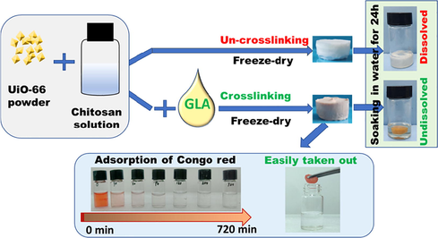
Chitosan/MOF composite porous monolith used in water remediation as adsorbent can realize high-efficient removal of pollutant in water and facile recycling from water. However, dissolution of chitosan (without crosslinking) in acidic aqueous solution will cause breakage of composite monolith. Herein, we report a chitosan/UiO-66 monolith prepared by ice-templating method. Specially, a pre-crosslinking treatment (by glutaraldehyde) is employed before the monolith formation, which obviously boosts its stability in aqueous solution. The composite monolith is evaluated by SEM, N2 adsorption, XRD, and batch adsorption tests for Congo Red (CR). The results show that the composite monolith possesses a typical ice-templating structure with hierarchical (mirco- / meso- and macro-) pores. UiO-66 particles are embedded on the surface of chitosan matrix, and the crystal structure of UiO-66 is not changed obviously by the crosslinking and freezing process. The composite monolith exhibits high adsorption efficiency (90% of CR was removed from its aqueous solution in 60 min) and the maximum adsorption capacity of 246.21 mg/g (derived from Langmuir model) can be reached. After adsorption, the monolith is collected by a facile procedure and recovered using ethanol for evaluating its reusability. After 4 cycles, the CR removal efficiency of the composite monolith still remains ∼90% of the initial efficiency. This work demonstrates that the simple crosslinking procedure before monolith formation can ensure the intact shape of the chitosan/MOF monolith during adsorption.
Keywords
Water treatment
UiO-66
Adsorption
Congo Red
Ice templating
Cross-linking

1 Introduction
Depletion of global clean water has become a big crisis to all mankind. Kinds of pollutants, such as heavy metal ions and organic dyes, are causing heavy pollution of water. Different routes have also been developed to relieve this crisis (Huang et al., 2018; Xue et al., 2018; Han et al., 2018; Salleh et al., 2011).
In the case of organic dyes, most of them may cause harmful to human and animal health due to their being toxic, mutagenic, carcinogenic (Bulut et al., 2008; Salleh et al., 2011). For example, Congo red (CR), one azo dye, could be metabolized into benzidine, which is linked to cancer of the human bladder (Puvaneswari et al., 2006; Shetti et al., 2019). CR also leads to decrease of serum protein concentration, platelet aggregation, thrombocytopenia, disseminated microembolism (Frid et al., 2007), and some allergic reactions (Puvaneswari et al., 2006; Chakraborty et al., 2003; Chatterjee et al., 2009; Chen et al., 2014). As such, it is really emergent to effectively remove some morbific dyes from water (Bhatt et al., 2012; Chen et al., 2015). So far, there are many ways to treat dye-contained wastewater, including adsorption (Tian et al., 2018; Beheshti et al., 2018), flocculation (Mittal et al., 2018; Kalantari et al., 2018; Zhao et al., 2018a,b), electrolysis (fu and Jian ,2016) and biodegradation (Gupta et al., 2013). Among them, the adsorption is an attractive and widely used method in the purification of dye-contained wastewater due to its high adsorption efficiency, easy operation and low cost (Gupta et al., 2013).
For the adsorption method, choosing suitable adsorbents plays a critical role for removal of target contaminations. Metal-organic frameworks (MOFs) are a new family of microporous materials consisting of metal clusters interconnected by organic ligands centered on transition elements (Ahmed and Jhung, 2014; Maurin et al., 2017). One of the most important properties of MOFs is their precisely defined apertures (from a few angstroms to a few nanometers) that can be controlled in a large range to allow size and shape selectivity toward guest species (Zhao et al., 2018a,b). Meanwhile, kinds of functional sites can be easily introduced on the framework, cavities and channels of MOFs for special applications (Park et al., 2012; He et al., 2013; Lin et al., 2016; Ahmed and Jhung, 2014; Chen et al., 2015).
Given these advantages, several MOFs have been employed for adsorption of contaminants from wastewater, (Ahmed et al., 2017; Li et al., 2016; Kumar et al.,2016; Han et al., 2018) such as MIL-Ti (adsorptive capacity of 1296 mg/g for Basic Red 46, and 1257 mg/g for Basic Blue 41, 862 mg/g for Methylene Blue (MB)) (Oveisi et al., 2017), Er-MOF(removing 92% of MB from wastewater) (Mohammadnejad et al., 2017) and UiO-66-NH2 with high adsorptive capacity for MB (555.6 mg/g) (Lv et al.,2019). Specially, for removal of CR from water, UiO-66 exhibits the adsorption capacity of ∼ 280 mg/g (Han et al., 2017) and ZIF-8 yields a really high adsorptive capacity of 798.0 mg/g (Fan et al., 2017). Furthermore, fabrication of MOF/polymer or MOF/carbon composites can boost the adsorption capacity obviously. For example, graphene oxide/metal–organic frameworks (GO/MOFs) can reach a removal capacity of 2489 mg/g for CR from aqueous (Du et al., 2019).
The use of MOF nanoparticles for remediation of water (involving liquid phase) can enhance mass transport due to high external surface area (Seo et al., 2015). However, this procedure causes the difficulty in collecting MOF nanoparticles after adsorption removal, which is usually performed by centrifugation or infiltration with nanoporous membranes (Ma et al., 2017). To address this issue, MOF monoliths (Lim et al., 2019) or MOF/polymer composites (Kalaj et al., 2019) have been prepared by kinds of ways, such as electrospinning (Duan et al., 2019), ice templating (Fu et al., 2017). Ice-templating is a highly versatile and efficient process to make a wide range of porous materials, including polymer, ceramics, and composites (Roleček et al.,2019; Suresh and Kumaraswamy, 2019; Fu et al., 2019). The resultant materials exhibit highly interconnected ice-templating macropores and contain porosity/properties contributed by nanoparticles and polymers in the materials (Lai et al., 2018; Deville, 2018). In our previous work, we fabricated a 3D porous polymer/MOF (chitosan/UiO-66) composite monolith using ice-templating and subsequent soaking in basic solution (for neutralizing residual acetic acid in chitosan, avoiding dissolution of chitosan monolith in water). This monolith was used for MCPP adsorptive separation from water and showed a high removal capability (Fu et al., 2017). However, alkaline solution caused the breakdown of UiO-66 crystal structure, leading to a sharp drop in special area surface. As such, in this work we substituted soaking in basic solution for chemical cross-linking by glutaraldehyde. The process of chemical cross-linking can ensure the intact figuration of the composite monolith and do not break crystal structure of UiO-66 at the same time. The adsorptive capacity for CR by the cross-linked chitosan/UiO-66 monolith was evaluated and adsorption isotherm, kinetic, influence of pH and recycling performance were studied as well.
2 Experimental section
2.1 Materials
Chitosan (<200 MPa.S), Zirconium chloride (ZrCl4) and benzene-1,4-dicarboxlate (H2BDC) were purchased from Macklin Biochemical Co., Ltd. (Shanghai, China). Glutaraldehyde (GLA, 50 wt%), acetic acid (HAc, 36 wt%), hydrochloric acid (HCl, 36 wt%), benzoic acid (BA) and N, N-Dimethylformamide (DMF) were bought from Aladdin Chemistry Co., Ltd. (Shanghai, China). Ultrapure water prepared using Milli Q system was used during this work. All of the reagents were used as received without further purification.
2.2 Preparation of adsorbent
2.2.1 Synthesis of UiO-66
ZrCl4 (2 mmol), BDC (2 mmol), benzoic acid (20 mmol), and HCl (36 wt%, 4 mmol) were dissolved into DMF (36 mL) with ultrasonic treatment for 10 min in a conical flask, covered with aluminum foil. The mixture was heated at 120 °C for 48 h, and white powder happens. The white powder of UiO-66 nanoparticles was collected by centrifugation and washed three times with DMF at room temperature.
2.2.2 Preparation of composite monolith
In this work, chitosan/UiO-66 composite monolith was prepared by combination of crosslinking & ice-templating as shown in Scheme 1. First, 1 wt% chitosan solution was prepared by dissolving 0.4 g chitosan powder in 39.56 mL 2 wt% HAc aqueous solution (ρ2 wt% HAc ≈ 1.001 g/cm3, prepared by diluting 36 wt% HAc with ultrapure water). Then 0.1 g UiO-66 plus 0.8 mL 5 wt% GLA (50 wt% GLA was diluted ten times using ultrapure water) were added to the 1 wt% chitosan solution (10 mL), with stirring at 60 °C. After 1 h, a light-yellow suspension was acquired. The suspension was transported into glass bottles (with the size of Φ16 mm × 33 mm, 1 mL per bottle), and the bottles were frozen at −20 °C for 12 h in a refrigerator. Then, the frozen samples were transferred into a freeze-dryer (SCIENTZ-12 N, Zhejiang, China) and freeze-dried for 24 h to form chitosan/UiO-66 monoliths. The monoliths were washed with deionized water and acetone in sequence (6 times every solution, 15 min every time) to remove residual acetic acid, and then soaked in cyclohexane for 4 h before air-drying in a fume hood. The resultant monolith (in Figure S1) was marked as Chitosan/UiO-66–1 (the number 1 means the mass ratio of chitosan to UiO-66 is 1:1). The chitosan monolith without UiO-66 was also prepared using the similar procedure and was named Chitosan-M.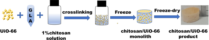
Procedure for formation of chitosan/UiO-66 monolith.
2.3 Adsorption experiments
A series of adsorption experiments were conducted to evaluate the adsorption properties of Chitosan/UiO-66–1, Chitosan-M and commercial activated carbon (AC) for CR. First, a stock solution of CR (1000 mg/L) was prepared by dissolving CR powder in ultrapure water and further diluted to the predetermined concentrations before use. The benchmark adsorption experiments were performed in glass bottles (with the size of Φ 22 mm × 50 mm) with 20 mg adsorbents (UiO-66 or Chitosan/UiO-66–1 or Chitosan-M) in 5 mL of CR solutions (50 mg/L, initial pH = 7.0) at 25 °C from 30 min to 1440 min. At a fixed time, the concentration of CR in the solution was measured using a UV–visible spectrophotometer (UV-1800 PC, Shanghai Meipuda instrument Co. Ltd., China). The specific adsorbed amount of CR was calculated according to the following equation:
The adsorption isotherm experiments were performed via altering the CR initial concentration from 50 mg/L to 500 mg/L (5 mg adsorbent in 5 mL CR aqueous solution). In order to ensure the achievement of adsorption equilibrium, the adsorption continued for 24 h. For all experiments, CR solutions were always motionless (without stirring of shaking) during adsorption process. Before all adsorption tests, the calibration curve (Figure S2) of CR concentration vs. UV absorbance at 490 nm was obtained using CR aqueous solutions with predeterminate concentration.
2.4 Material characterization
Nitrogen (N2) adsorption–desorption measurements were carried out using a Micromeritics ASAP 2020 HD88 system after pretreatment at 120 °C for 48 h. The specific surface areas, pore volumes and pore size distribution of UiO-66 powder and Chitosan/UiO-66–1 monolith were calculated by Brunauer-Emmett-Teller (BET) and Density Functional theory (DFT) methods. XRD patterns were acquired using an X-ray powder diffractometer with Cu anode (Bruker/D2), running at 40 kV and 30 mA, scanning from 5 to 70°. Before XRD evaluation, the chitosan/UiO-66 composite monolith was quenched using liquid nitrogen then pulverized. Morphologies of the samples were taken using a scanning electron microscope (SEM, VEGA 3SBU, Bruker). The samples were sputtered with a thin layer of Au prior to SEM imaging using plasma sputter instrument (JS-1600).
3 Results and discussion
3.1 Characterization of samples
In this work, UiO-66 particles were synthesized by solvothermal method successfully. The as-synthesized UiO-66 exhibits polygon figuration as shown in Fig. 1B. When the mixture of UiO-66 and chitosan was crosslinked using glutaraldehyde and subsequently subjected to freezing and freeze-drying, the lamellar structures are observed in Fig. 1C. At higher magnification (Fig. 1D), it is clear that UiO-66 particles uniformly distribute on the surface of Chitosan/UiO-66–1, some embed in the chitosan pores wall and some just on the top surface (while surface of Chitosan-M is smooth as shown in Fig. 1A.). The similar morphology was also discerned in our previous work (freeze-drying chitosan/UiO-66 composite without GLA treatment) (Fu et al., 2017). This indicates that crosslinking by GLA may not change the morphology of the freeze-dried composite monolith obviously. In addition, in the previous work (Fu et al., 2017), in order to maintain the configuration of the freeze-dried monolith in water, the as-dried monoliths were washed in NaOH aqueous solution for remove HAc remaining in chitosan matrix; however, some UiO-66 particles were washed away in this procedure. In this work no obvious abscission of UiO-66 was observed.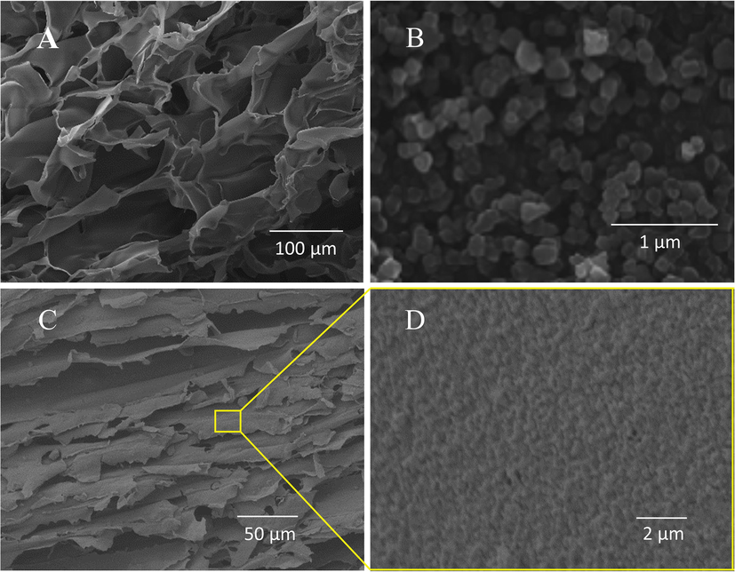
SEM images:(A) Chitosan-M, (B) UiO-66 nanoparticles, (C)&(D) Chitosan/UiO-66–1.
The XRD patterns for the UiO-66 particles and Chitosan/UiO-66–1 are showed in Fig. 2. The diffraction peaks at 2θ = 7.1°, 8.4°, 11.9°, 16.9°,22.1°, 25.6°, 30.6° are corresponding to UiO-66 (1 1 1), (0 0 2), (0 2 2), (0 0 4), (1 1 5), (2 2 4), (0 4 6) crystal planes, respectively, indicating UiO-66 was successful synthesized (Cavka et al., 2008). Chitosan/UiO-66–1 shows the same main characteristic Bragg peaks, suggesting successful doping of UiO-66 in the composites without pronounced phase structure change, which is similar with the other research (Jin et al., 2018). Only some characteristic peaks are not quite obvious, which may be caused by coating of glutaraldehyde and chitosan molecules on the surface of UiO-66.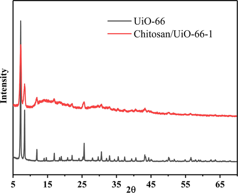
XRD patterns of UiO-66 and Chitosan/UiO-66–1.
The surface area of the obtained materials was evaluated through N2 adsorption/desorption isotherms. The isotherms of UiO-66 (shown in Fig. 3A) is identified as typical type Ι, which is characteristic of microporous materials. Pore size distribution calculated using DFT theory confirms the existence of micropores (Fig. 3B). For Chitosan/UiO-66–1, the isotherm (Fig. 3A) slowly increases at low relative pressure suggesting the presence of mesopores. When relative pressure is close to 1, the isotherm appears to fast increase due to the presence of macropores. The pore size distribution of the composite monolith (Fig. 3B) demonstrates the co-existence of micro-, meso- and macro-pores. The special surface area was calculated using BET method. UiO-66 powder possesses a surface area of 1034 m2/g that is similar to the reported value (Valenzano et al., 2011). However, the special surface area of Chitosan/UiO-66–1 (122 m2/g) exhibits a large decrease compared with UiO-66 powder. This sharp decrease of BET surface was also reported in other MOF/polymer hybrids (Duan et al., 2019 Valenzano et al., 2011). The plausible reason is (1) chitosan matrix mainly contribute to mass but little to surface area (Fu et al., 2017), that is, 50% decrease of surface area may be caused by introduction of chitosan matrix; (2) glutaraldehyde molecules enter the inside or cover the surface of the UiO-66 particles, blocking the micro/mesopores; (3) the chitosan molecules encapsulate the UiO-66 nanoparticles, preventing them from contacting with adsorbates.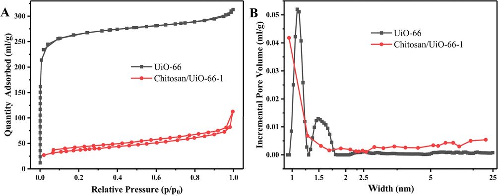
(A) N2 adsorption/desorption isotherms; (B) pore size distribution profiles.
3.2 Adsorption of CR
3.2.1 Adsorption isotherms
In order to obtain the theoretical adsorption capacity and evaluate the adsorption isotherms, we carried out a set of benchmark adsorption experiments. The Langmuir and Freundlich models were also used to describe the adsorption data. The Langmuir isotherm can be expressed in linear form using the follows equation:
Fig. 4A. As it shows, equilibrium uptake increases with the rise of equilibrium CR concentration at the range of experimental concentrations. During adsorption, the higher concentration of adsorbate could provide the stronger driving force of solution, as a result, the active sites of adsorbent are surrounded by more adsorbate. Compared with Chitosan-M, UiO-66 and Chitosan/UiO-66–1 can easily achieve adsorptive equilibrium under relatively lower CR concentration, indicating UiO-66 in the hybrid plays a main role in CR adsorptive removal. The chitosan matrix also boosts the adsorption of CR because Chitosan/UiO-66–1 presents higher equilibrium adsorption capacity than UiO-66 at the same concentration. This phenomenon suggests, in static adsorption process, that chitosan matrix can support the UiO-66 particles avoiding the aggregation of the particles and decrease of active sites.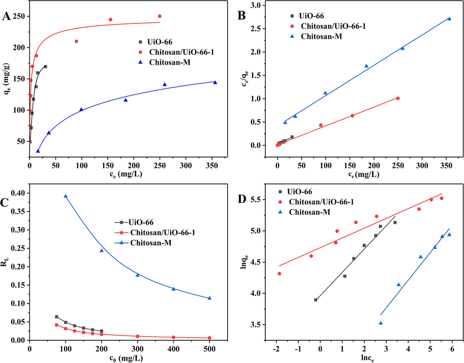
(A) Adsorption isotherms; (B) Langmuir isotherm plot; (C) RL values at different initial concentrations of CR aqueous solution; (D) Freundlich isotherm plot.
A linear relationship is obtained when ce/qe is plotted against ce (Fig. 4 B), then qmax and kL can be calculated from the slope and intercept. The relevant results are shown in Table 1. The coefficients of determination R2 > 0.99 means that the adsorption of CR on UiO-66, Chitosan/UiO-66–1 and Chitosan-M is consistent with Langmuir's model well, which indicates adsorption of CR on the three samples are monolayer and uniform adsorption. The maximum adsorption capacities of the adsorbents were calculated according to Langmuir equation. The capacity is 246.91 mg/g for Chitosan/UiO-66–1, 199.2 mg/g for UiO-66 and 153.85 mg/g for Chitosan-M. It is worth noting that although the special surface area of Chitosan/UiO-66 is lower than UiO-66 (just around 1/9 that of UiO-66), the composite monolith substantiates the better adsorptive capacity than UiO-66, which indicates the BET surface is not the exclusive factor to determine the adsorption performance. Given the size of the CR molecule (∼2.48 nm, in Figure S3), it cannot enter into the micropores (<2 nm) of UiO-66. As such, the internal surface of micropores does not contribute to adsorption capacity. So, the CR molecules are mainly adsorbed on the external surface of the UiO-66 particles. By contrast, Chitosan/UiO-66–1 possesses meso- and macro-pores, which can provide plenty effective adsorptive sites for adsorption CR molecule. Note: qe,exp is the experimental equilibrium adsorption capacity.
Langmuir
Freundlich
qmax(mg/g)
KL(L/mg)
R2
1/n
KF(L/g)
R2
qe,exp(mg/g)
UiO-66
199.20
0.1951
0.996
0.3725
52.67
0.973
169.56
Chitosan/UiO-66–1
246.91
0.3063
0.997
0.1558
113.44
0.935
250.20
Chitosan-M
153.85
0.0156
0.996
0.4420
11.50
0.962
109.88
In previous research UiO-66 can adsorb CR 283 mg/g (Han et al., 2018); however, the experimental value is only 169.56 mg/g adsorbed by UiO-66 in this work as shown in Table 2. There are two plausible reasons: (1) the UiO-66 particles in this work show lower mesoporous volume (0.047 cm3/g) than that of UiO-66 in previous work (0.06 cm3/g), so as to provide fewer available active sites for adsorption of CR; (2) static adsorption is employed in this work, compared to the static process oscillation can boost material transport onto MOFs particles.
sample
qe,exp (mg/g)
Adsorption method
Experimental Temperature (℃)
BET surface (m2/g)
UiO-66
169.56
static
25
1034
This work
UiO-66
283.00
shaking
35
1358
(Han et al., 2018)
Chitosan/UiO-66–1
250.20
static
25
122
This work
There is another parameter RL, which is dimensionless balance parameter. It can be used to determine whether the isotherm is favorable for adsorption: irreversible (RL = 0), favorable (0 < RL < 1), linear (RL = 1) or unfavorable (RL > 1).
The linear Freundlich isotherm equation is expressed as:
where kF is a Freundlich constant related to adsorption capacity (L/g), the higher value of kF indicates adsorption is feasible. The constant n is a measure of deviation from linearity of the adsorption and usually used to verify types of adsorption. It is suggested that if 1/n = 1, the adsorption is linear; further, 1/n > 1 indicates that adsorption may be a chemical process; whereas, 1/n < 1 is associated with a favorable adsorption and it also may have a physical process (Prabhu and Meenakshi, 2015; Dawood and Sen 2012; Vimonses et al., 2009). A straight line was obtained when lnqe was plotted against lnce (Fig. 4D) and the values of 1/n and kF were calculated from the slope and intercept. The data are listed in Table 1. The values of 1/n are between 0 and 1 for all samples, which confirms the samples are favorable for adsorbing CR molecules and some physical processes exist. Among the three adsorbents Chitosan/UiO-66–1 possesses the highest value of kF indicating its best adsorptive performance.
3.2.2 Adsorption kinetics
The effect of time on the adsorption capacity of the three samples is shown in Fig. 5 A. When the initial CR concentration is 50 mg/L, the adsorption capacity of CR on the three samples increases fast during the first stage and then levels off after 60 min. The initial fast increase of adsorptive capacity is primarily caused by the abundant availability of active sites on the surface of the adsorbent (Bentahar et al., 2017; Huang et al., 2017). After a period of time, all active sites are gradually occupied by CR molecules leading to the decrease of adsorption efficiency in the second stage (Dawood and Sen, 2012). The adsorbed quantities of CR over Chitosan/UiO-66–1 and UiO-66 are much higher (11.599 mg/g and 11.767 mg/g in 60 min, respectively) than that over AC (6.96 mg/g) in this study. During the process of adsorption, Chitosan/UiO-66–1 shows a high adsorptive effectiveness. The CR aqueous solution almost becomes absolute transparent after 90 min as shown in the inset photograph in Fig. 5A.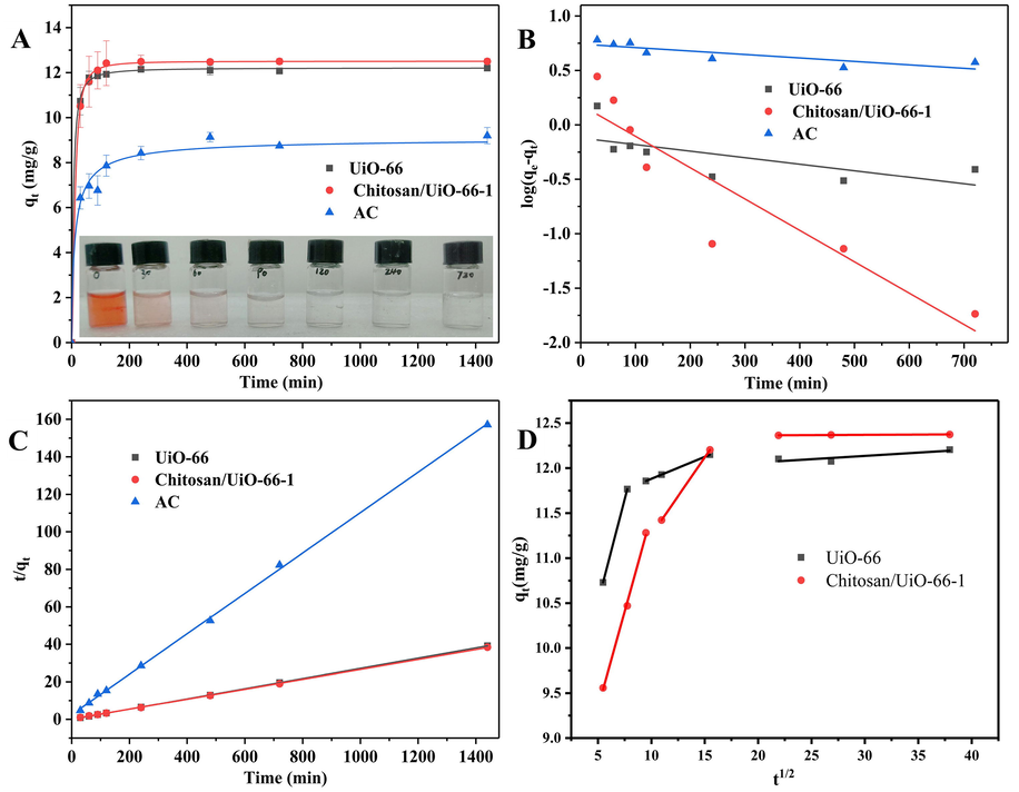
(A) Effects of time on adsorption capacity of UiO-66, Chitosan/UiO-66–1 and AC for CR. Adsorption experiments: concentration 50 mg/L; sample dosage: 20 mg in 5.00 mL; pH = 7.0; (B) Pseudo-first-order model; (C) Pseudo-second-order model; (D) intraparticle diffusion model.
Adsorption kinetics was analyzed using Pseudo-first-order kinetics, Pseudo-second-order kinetic models and intraparticle diffusion model (Wang et al., 2007) to discover the adsorption mechanism. For Pseudo-first-order kinetics model, the adsorption rate is expected to be proportional to the first power of concentration, where the adsorption is characterized by diffusion through a boundary. Where Pseudo-second-order model assumes that chemisorption may be the rate-controlling step in the adsorption processes (Xu et al., 2019). The pseudo-first-order kinetic equation and the pseudo-second-order kinetic equation could be expressed with:
Pseudo-first-order
Pseudo-second-order
sample
qe,exp(mg/g)
K1(1/min)
qe(mg/g)
R2
K2(1/min)
qe(mg/g)
R2
UiO-66
12.205
7.23 × 10⁻⁴
0.66
0.4203
0.0045
36.76
1
Chitosan/UiO-66–1
12.499
3.39 × 10⁻⁷
1.25
0.6843
0.0020
37.75
0.9999
AC
9.197
4.00 × 10⁻⁷
5.16
0.6324
0.0039
9.28
0.9994
Since neither the Pseudo-first-order nor the Second-order model can identify the diffusion mechanism, the kinetic results were analyzed by the intraparticle diffusion model to elucidate the diffusion mechanism whose model is expressed as:
sample
k1 (mg/g min1/2)
R2
k2 (mg/g min1/2)
R2
k3 (mg/g min1/2)
R2
UiO-66
0.45674
1
0.04863
0.9999
0.00731
0.76897
Chitosan/UiO-66–1
0.42793
0.99822
0.1717
1
0.00059
0.95693
3.3 Recycling of adsorbents
The recovery and reusability of the adsorbent are very important for commercial and industrial applications. Although UiO-66 nanoparticle has been demonstrated to be high-performance adsorption for methyl orange and methylene blue, it is difficult to recover (Molavi et al., 2018). Generally, UiO-66 nanoparticle can only be collected by centrifugation or filtration (Molavi et al., 2018; He et al., 2014), which is a tedious process and will limit the upscale applications. To solve this issue, a MOF/polymer composite monolith (Chitosan/UiO-66–1) was fabricated to facilitate recycling of adsorbents in this work. As shown in Fig. 6A, the composite monolith can be taken out just by a pair of tweezers at the end of adsorption. It is clear that chitosan/UiO-66 composite monolith becoming red due to CR molecules attached on the monolith. This simple picking-up procedure can accelerate the recycling process for saving time and reducing energy consuming.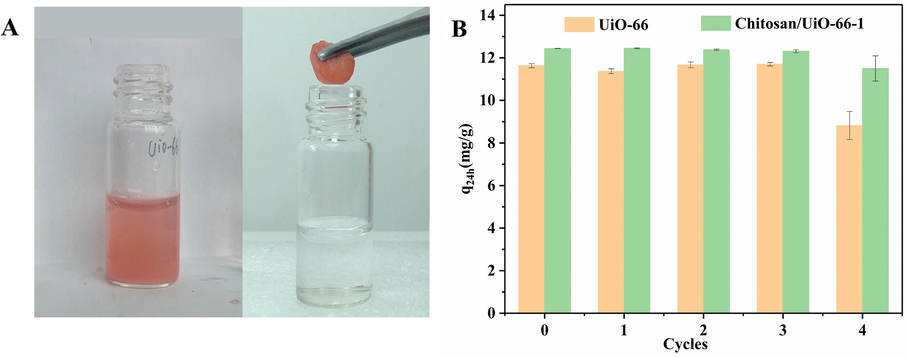
(A) Digital picture of UiO-66 (left) and Chitosan/UiO-66–1(right) during recycling, and the latter can be taken out by a simple picking-up; (B) reusability of UiO-66 and Chitosan/UiO-66–1 for the adsorptive removal of CR from 5 mL of 50 mg/L CR aqueous solution.
Chitosan/UiO-66–1 and UiO-66 powder were collected by picking out and centrifugation, respectively. Both the samples were washed sequentially with absolute ethanol (4 times, 30 min every time), acetone (3 times, 15 min per time), cyclohexane (3 times, 15 min per time), then were naturally air-dried for 48 h in a fume hood for the next cycle of adsorption experiment. The adsorptive uptake in 24 h (q24h) was used to observe their recycling adsorption capacity. As shown in Fig. 6 B, after four cycles, the values of q24h of UiO-66 powder and Chitosan/UiO-66–1 are 8.815 mg/g and 11.497 mg/g, respectively. Chitosan/UiO-66–1 can retain over 90% adsorbed capacity of the fresh adsorbent, which demonstrates the composite monolith is a promising adsorbent for CR removal from water.
4 Conclusions
In this work, the chitosan/UiO-66 composite monolith was successfully prepared by ice templating method. Crosslinking procedure with GLA prevented the composite from dissolving in water, and did not change the typical ice-templated porous layered structure. Although the composite monolith presented a relatively low special surface area compared with UiO-66 powder due to plausible encapsulation of UiO-66 in chitosan and blockage of micropores, it still exhibited high adsorptive efficiency for CR from static wastewater. The chitosan/UiO-66 monolith can remove almost all CR from 50 mg/L CR aqueous solution within 90 min. This suggests the chitosan matrix can make active sites on UiO-66 contact with adsorbates enough by holding up the particles, avoiding their overlapping. Furthermore, the method of preparing composite monolith provides a facile recycling method. These merits make it a promising adsorbent for dyes adsorption removal.
Acknowledgement
The work was supported by National Natural Science Foundation of China (51902216), Foundation of Sichuan Provincial Department of Education (Grants 18ZA0351), Project of Science and Technology Department in Sichuan province (Grants 2018JY0493), Foundation of Introduced Talent of Sichuan University of Science and Engineering (Grants 2017RCL27), Foundation of Key Laboratory of Automobile High Performance Materials and Forming Technology of Sichuan Province (Grants SZJJ2017-017) and Innovation Fund for Postgraduate of Sichuan University of Science and Engineering (Grants y2018047).
References
- Mater. today. 2014;17:136-146.
- Chem. Eng. J.. 2017;321:40-47.
- J. Solid State Chem.. 2018;258:618-627.
- J. Environ. Chem. Eng.. 2017;5:5921-5932.
- RSC adv.. 2012;2:8663-8671.
- Dyes pigments.. 2005;65:51-59.
- J. Hazard. Mater.. 2008;154:613-622.
- J. Am. Chem. Soc.. 2008;130:13850-13851.
- Sep. Purif. Technol.. 2003;31:141-151.
- Bioresource Technol.. 2009;100:2803-2809.
- Applied Surface Science.. 2015;327:77-85.
- Chem. Eng. J.. 2014;242:226-233.
- Water Res.. 2012;46:1933-1946.
- Scripta Mater.. 2018;147:119-124.
- International Journal of Nanoscience.. 2019;18:1850030.
- J. Am. Chem. Soc.. 2019;141:7589-7595.
- Mater. Res. Express. 2017;4:026404
- Brain Res. Rev.. 2007;53:135-160.
- ACS appl. Mater. Inter.. 2017;9:33979-33988.
- Ind. Eng. Chem. Res.. 2019;58:14312-14322.
- Adv. Colloid. interfac.. 2013;193:24-34.
- J. Clean. Prod.. 2018;188:575-588.
- Front.. 2017;4:1870-1880.
- ACS Appl. Mater. inter.. 2013;5:8796-8804.
- J. Haxard. Mater.. 2018;348:109-116.
- Mater. Chem. Phys.. 2017;202:266-276.
- J. Mater. Chem. A. 2018;6:20473-20479.
- Angew. Chem. Inter. Ed.. 2019;58:2336-2340.
- Sep. Sci. Technol.. 2018;53:2527-2535.
- Eur. J. Inorg. Chem.. 2016;2016:4373-4377.
- J. Environ. Sci. 2018
- Chinese J. Chem.. 2016;34:175-185.
- ACS Materials Letters.. 2019;1:147-153.
- J. Colloid. interfac.. 2016;461:79-87.
- Mat.. 2019;282:179-187.
- Chem. Eng. J.. 2017;313:890-898.
- Chem. Soc. Rev.. 2017;46:3104-3107.
- Int. J Biol macromol.. 2018;114:283-294.
- J. Porous Mat.. 2017;25:1-9.
- Appl. Surf. Sci.. 2018;445:424-436.
- J. Hazard. Mater.. 2017;347:123-140.
- J. Am. Chem. Soc.. 2012;134:20110-20116.
- Desalin. Water Treat.. 2015;53:3592-3603.
- J. Eur. Soc.. 2019;39:1595-1602.
- Desalination.. 2011;280:1-13.
- Chem. Eng. J.. 2015;270:22-27.
- Microchem. J.. 2019;146:387-392.
- J. Phys. D. Appl. Phys.. 2019;52:214002
- Chemosphere. 2018;208:476-483.
- Chem. Mater.. 2011;23:1700-1718.
- Chem. Eng. J.. 2009;148:354-364.
- Clean Technol.. 2007;82:711-720.
- Waste Manage.. 2019;87:652-660.
- Chem. Engin. J.. 2017;323:502-511.
- J. Hazard. Mater.. 2018;341:381-389.
- Sci. Total. Environ.. 2018;640:243-254.
- Adv. Mater.. 2018;30:1705189.
Appendix A
Supplementary data
Supplementary data to this article can be found online at https://doi.org/10.1016/j.arabjc.2020.04.007.
Appendix A
Supplementary data
The following are the Supplementary data to this article:Supplementary data 1
Supplementary data 1


