

Translate this page into:
Nano-engineered ZnO/CeO2 dots@CNFs for fuel cell application
⁎Corresponding authors at: Department of Organic Material & Fiber Engineering, Chonbuk National University, Jeonju 561-756, Republic of Korea. Tel.: +82 632702363; fax: +82 632702348 (N.A.M. Barakat) and (H.Y. Kim). nasser@jbnu.ac.kr (Nasser A.M. Barakat), khy@jbnu.ac.kr (Hak Yong Kim)
-
Received: ,
Accepted: ,
This article was originally published by Elsevier and was migrated to Scientific Scholar after the change of Publisher.
Peer review under responsibility of King Saud University.
Abstract
Well-dispersed ZnO(x)CeO2(1−x) nanodots@carbon nanofibers as anode catalysts for the electrooxidation of methanol were synthesized by an easy-controlled template-free method. Their structure and morphology were characterized by X-ray diffraction (XRD), high resolution transmission electron microscopy (HR-TEM), field-emission scanning electron microscopy (FESEM) equipped with rapid EDX (energy dispersive analysis of X-ray). The appealed characterization techniques specified that the obtained material is carbon nanofibers decorated by ZnO and CeO2 nanodots. The electrochemical oxidation of methanol on ZnO(x)CeO2(1−x) nanodots@CNFs modified glassy carbon electrode in alkaline solutions was systematically evaluated by cyclic voltammetry (CV) method. A detailed investigation is made for the electrocatalytic oxidation of methanol by varying methanol concentration. The corresponding current densities of ZnO(60%)CeO2(40%) nanodots@CNFs and ZnO(40%)CeO2(60%) nanodots@CNFs were 5.3 and 16.3 mA/cm2, respectively. Moreover, negative onset potential (−50 mV vs. Ag/AgCl) was observed when ZnO(40%)CeO2(60%) nanodots@CNFs were utilized, which is a superior value among the reported non-precious electrocatalysts. These results suggested cheap and effective nanomaterials as non-precious catalyst for DMFCs application and pave the way to further improve the performance in energy and environmental applications.
Keywords
Carbon nanofibers
Nanodots
Electrospinning
Direct methanol fuel cells
Negative onset potential

1 Introduction
Environmental conditions and global warming have become of supreme importance at the current time for everyone especially for researchers (Ghouri et al., 2015c,b; Zafar Khan Ghouri, 2015). The environmental conditions turn into inferior each day, and this entire condition happens due to human activities (Ghouri et al., 2015a,b; Zafar Khan Ghouri, 2015).
Among various human activities, production of power is chief bustle compliant an adverse impact on the atmosphere. Therefore, decreasing greenhouse gases emission, mainly CO2, from the energy production is a fundamental component in accomplishing planned goal pointing to mitigate environment change (Lucia, 2014; Ghouri et al., 2015b; Zafar Khan Ghouri, 2015). Accordingly, generation of energy without the release of deadly gases is crucial in the current situation.
In consequence, alternative energy resources accepted for energy generation comprise the use of solar, wind and water. However, these green technologies are inadequate to accomplish the current energy requirements (Hagfeldt et al., 2010; Miller and Simon, 2008; Dunn et al., 2011; Jacobson et al., 2005; Ghouri et al., 2015a).
Fuel cell is a good technological option for resolving energy and environmental problems and in particular, direct methanol fuel cells (DMFCs) have appealed noteworthy attentions due to their merits, such as methanol is a low-cost, readily accessible, and simply stored and transported liquid fuel. Moreover, methanol can be produced from green sources so it can be considered a renewable and green energy source (Ghouri et al., 2015b; Barakat et al., 2014).
It is well known the electrode materials are the crucial factor to authenticate the properties of the fuel cell; Pt is considered to be the universal choice as an electrocatalyst in DMFCs electrode. However, use of expensive and scarce platinum in fuel cells technology has hampered the commercialization of this technology worldwide (Wang et al., 2011). Nonetheless, one of the major concerns associated with Pt-based electro catalyst is the intermediate product poisoning which blocks the active sites of Pt (Ghouri et al., 2015b,c). Therefore, intensive research has been devoted to find alternative materials to be used as electro catalyst for catalyzing the reactions involved in fuel cell based energy production.
In this regard, frequent research has been dedicated on the development of various catalysts based on metal oxides such as CeO2, TiO2 and NiO with low cost than Pt, Pd and Ag (Steele and Heinzel, 2001; Stassi et al., 2013; Ghouri et al., 2015c; Zhao et al., 2013; Zhang et al., 2012; Singh and Buttry, 2012; Li et al., 2012). Recently, rare earth oxides have been received significant consideration because they reveal a number of advantages. In particular, ceria (cerium oxide) is a technologically important rare earth family based material because the applications of cerium have become more and more widespread (Wells Jr and Wells, 2001). Moreover, cerium oxide is a well known material as a promoter in three-way catalysts (TWCs) for the oxygen sensors, glass-polishing materials, ultraviolet absorbent, low-temperature water–gas shift (WGS) reaction, elimination of toxic auto-exhaust gases, oxygen permeation membrane systems, electrochromic thin-film application as well for fuel cells applications (Trovarelli, 1996; Kašpar et al., 1999; Fu et al., 2001,2003; Beie and Gnörich, 1991; Jasinski et al., 2003; Stoukides, 2000; Yin et al., 2006; Park et al., 2000; Sun et al., 2009; Sun and Stimming, 2007; Feng et al., 2006; Armini et al., 2008; Porqueras et al., 2003; Ghouri et al., 2015c; Yan et al., 2014; Liu et al., 2014).
The electro catalytic activity of metal oxide species can be improved by supporting on suitable co-catalyst support. Zinc oxide (ZnO) has recently been identified as a promising material which demonstrates both semiconducting and piezoelectric characteristics simultaneously (Xiao et al., 2015). In addition, as a bulk carbonaceous material, carbon nanostructures have attracted great attentions due to its marvelous physicochemical characteristics and most widely studied as an electrocatalyst in all kinds of fuel cells (Wang et al., 2004; Li et al., 2003; Steigerwalt et al., 2001; Ghouri et al., 2015c). Particularly, carbon nanofiber has acknowledged much significance due to intensified consciousness of the prospective applications in many fields (Ghouri et al., 2015c,b,a).
The material processing technique of electrospinning is an electrostatically induced self-assembly technology for the fabrication of fibers with diameters typically ranging from tens to hundreds of nanometers (Dzenis, 2004; Greiner and Wendorff, 2007). In light of the noble morphological structure, high electrical conductivity, and controllable pore size distribution of electrospun carbon nanofibers, it is obviously predictable to have a high catalytic activity for DMFCs, which has been confirmed recently by the same author (Ghouri et al., 2015c,a,b).
Herein, we report low cost and high yield route to prepare ZnO(x)CeO2(1−x) nanodots@CNFs composite. The presented ZnO(x)CeO2(1−x) nanodots@CNFs composite are prepared by calcination of electrospun nanofibers comprising of cerium acetate, zinc acetate and poly (vinyl alcohol) in argon environment at 700 °C. To understand the electrochemical characterization of ZnO(x)CeO2(1−x) nanodots@CNFs composite, their uses for the methanol electrooxidation were investigated by cyclic voltammetry (CV) measurement; the nanofibers containing ZnO(40%)CeO2(60%) showed the maximum activity.
2 Experimental
2.1 Materials
Zinc acetate di-hydrate (ZnAc, 99.0%) and Cerium (III) acetate hydrate (CeAc, 99.9%) were bought from Junsei Chemicals Corporation Ltd, Japan, and Sigma-Aldrich Corporation, St. Louis, MO, USA, respectively. Poly (Vinyl alcohol) (PVA) with a molecular weight 65,000 g/mol and Nafion 117 was also obtained from Sigma-Aldrich Corporation, St. Louis, MO, USA. 2-Propanol (99.7%) and glassy carbon electrode were purchased from J.T. Baker, USA, and ALS Co, Ltd, Japan, respectively while double point distilled water was used as solvent.
2.2 Preparation of ZnO(x)CeO2(1−x) nanodots@CNFs
In a typical procedure, ZnAc and CeAc aqueous solution were prepared by dissolving different amounts of ZnAc and CeAc (total amount of ZnAc & CeAc was 1 g) in 5 ml deionized water and magnetically stirred for 10 h at 50 °C in water bath. After cooling down to room temperature, the mixture was poured in to a solution containing 20 g PVA aqueous solution (10 wt%) and was vigorously stirred at 60 °C for 10 h to get see-through, clear and consistent mixture. Next, the homogeneous solution was electrospun at a high voltage of 23 kV using DC power supply at room temperature with 65% relative humidity. The distance between needle tip (positive electrode) and rotating cylinder (negative electrode) was kept constant at 20 cm. The final ready nanofiber mats were initially dried at room temperature for 24 h and then under vacuum for 24 h at 75 °C, and finally the dried nanofibers were calcined at 700 °C for 7 h in argon atmosphere with an heating rate of 2.0 °C/min. Fig. 1 shows a schematic illustration of the synthesis of ZnO(x)CeO2(1−x) nanodots@CNFs composite.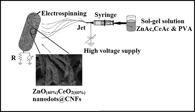
Schematic diagram for the whole process and the final product.
2.3 Sample characterization
The phase and crystallinity of the composite were characterized by X-ray diffract meter (XRD, Rigaku, Japan) with Cu Kα (λ = 1.54056 Å) radiation operating at 45 kV and 100 mA over a range of 2θ angle from 10° to 80°, scanning at a rate of 4°/min. The morphology of the composite was observed by field-emission scanning electron microscopy (FESEM, Hitachi S-7400, Japan) coupled with rapid EDAX (energy dispersive analysis of X-Ray) analysis for composition and distribution of elements with the incident electron beam energies ranging from 3 to 30 keV, which impinges the sample surface from the normal angle. High resolution TEM images and selected area electron diffraction patterns were observed by JEOL JEM-2200FS transmission electron microscope (TEM) operating at 200 kV equipped with EDX (JEOL, Japan).
2.4 Electrode preparation and electrochemical measurement
Preparation of the working electrode was carried out by mixing 2.0 mg of the electro-catalyst, 20 μL of Nafion solution (5 wt.%) and 400 μL of isopropanol. The slurry was sonicated for 30 min at room temperature. The ultrasonically dispersed nanocatalyst (15 μL) was spread by micropipette on to the active area of the glassy carbon electrode which was then subjected to drying process at 80 °C for 20 min. The glassy carbon working electrode with 3 mm of diameter and 0.0706 cm2 of apparent electrode area was polished with diamond suspension to a mirror finish before being used.
The electrochemical measurements were taken in conventional three electrode electrochemical cell (VersaSTAT 4, USA) at room temperature in different concentrations of Methanol (1 M KOH) solution. A glassy carbon electrode made in the above mentioned procedure was used as a working electrode while Pt wire and an Ag/AgCl electrode were used as the auxiliary and reference electrodes, respectively. All potentials were quoted with regard to the Ag/AgCl electrode. Normalization of the current density was achieved based on the surface area of the utilized glassy carbon electrode (0.0706 cm2).
3 Result and discussions
Fig. 2. displays X-ray diffraction measurement for the obtained composite after the proposed calcination process. The obtained pattern indicates that the composite contains ZnO and CeO2 metal oxides. The strong diffraction peaks at 2θ values of 28.37°, 32.87°, and 47.18° corresponding to (1 1 1), (0 0 2), and (0 2 2) crystal planes respectively indicate the formation of cubic fluorite structure of CeO2 with lattice constants a = b = c = 5.440 Å; α = β = γ = 90° [space group: Fm3m (2 2 5)] according to JCPDS no: 81-0792, the locations of CeO2 standard peaks are displayed as orange vertical lines at the corresponding 2θ values. Additionally, the fluorite structure comprises of face-centered-cubic (FCC) unit cell of cations with anions inhabiting the octahedral interstitial sites (Ghouri et al., 2015c); the most noticeable peak at 28.37° can be correlated with (1 1 1) hkl indices signifying that CeO2 structure mainly grows along the (1 1 1) face. Along with other strong diffraction peaks, X-ray diffraction shape clearly reveals that the crystallinity of CeO2 nanostructure obtained is good. Moreover, the remaining observed peaks at 2θ values of 31.69°, 34.38°, 36.18°, 56.46°, 67.8°, and 76.78°, corresponding to (1 0 0), (0 0 2), (1 0 1), (1 1 0), (1 1 2), and (2 0 2) planes, respectively articulate the formation of (hexagonal) wurtzite-type ZnO with lattice constants a = b = 3.2568 Å, c = 5.2125 Å; α = β = 90°, γ = 120° [space group: P63mc (1 8 6)] according to JCPDS no: 01-079-0207, the locations of standard peaks of ZnO are assigned by green vertical lines at the corresponding 2θ values.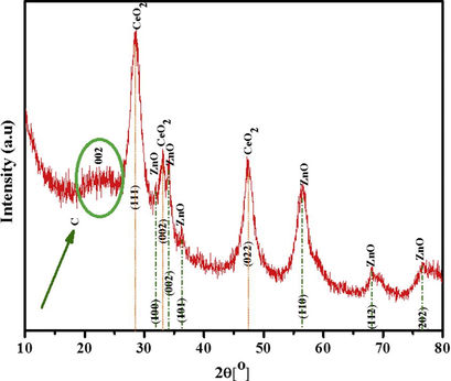
XRD pattern for the obtained ZnO(40%)CeO2(60%) nanodots@CNFs after calcination at 700 °C for 7 h in argon atmosphere.
Furthermore, a low intensity and broad peak appear at around near 2θ = 20–25° (marked be green circle & arrow), consistent with the (0 0 2) reflection for graphitic carbon.
Finally, XRD observation confirmed that hexagonal ZnO and Cubic CeO2 structures coexist in the nanocomposite.
The morphology of the synthesized ZnO(40%)CeO2(60%) nanodots@CNFs composite after the calcination process was examined by FESEM images, given in Fig. 3. The image clearly shows the formation of nanodots with irregular shapes and are densely scattered all over the surface of the carbon nanofibers which are expected to be bimetallic oxides of Zn and Ce. Compared to cerium which has high melting point (1068 K), zinc can relatively melt at lower temperature (692 K). Moreover, our previous studies indicated that calcination of the acetate salts in inert atmosphere leads to form reducing gases (mainly CO and H2) (Afeesh et al., 2012; Barakat et al., 2010; Barakat et al., 2009; Barakat and Motlak, 2014a), so it is expected that some Zn has been formed and oxidized on the surface of the nanofibers. Accordingly, the observed very thin nanorods in FESEM image can be assigned to ZnO.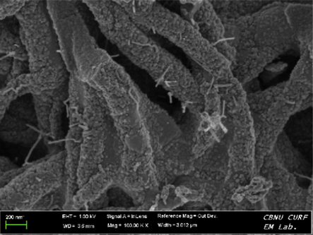
FESEM image of produced ZnO(40%)CeO2(60%) nanodots@CNFs after calcination at 700 °C for 7 h in argon atmosphere.
SEM-EDX was employed to analyze the chemical composition of the final product, Fig. 4 shows the SEM image of the ZnO(40%)CeO2(60%) nanodots@CNFs composite after the calcination process and the corresponding energy dispersive X-ray spectroscopy(EDX) analysis, as shown in figure nanocomposite is made of C, O, Ce and Zn.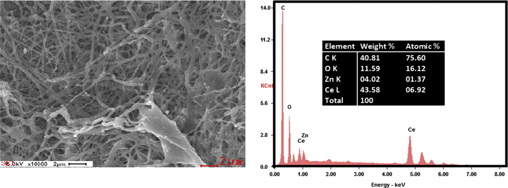
SEM images with corresponding EDS maps for C, O, Ce, and Zn.
Composition of ZnO(40%)CeO2(60%) nanodots@CNFs obtained by SEM-EDX is summarized inset in (Fig. 4).
For a more painstaking examination of the morphological and structural features of the ZnO(40%)CeO2(60%) nanodots@CNFs structure were also made by transmission electron microscopy (TEM), high resolution transmission electron microscopy (HR-TEM) and selected-area electron diffraction (SAED).
TEM-images (Fig. 5(a)) indicate that the nanofiber morphology with several ZnO/CeO2 nanodots is adhered on the surface of nanofiber (marked by red arrows); the magnified images (Fig. 5(b)) show that the as-synthesized nanofiber consists of many nanodots with a diameter around 4 nm. The corresponding HRTEM-image (Fig. 5(c and d)) noticeably shows the lattice fringes conforming to highly crystalline nature of the composite; moreover, checking the distance between the crystal planes specified that there are two dissimilar kinds of crystalline nanodots. Remarkably, measuring these planar distances and matching with the standard cell parameters of ZnO and CeO2 confirmed that these nanodots are CeO2 and ZnO as the measuring planar spaces are 3.17 and 2.85 Å which are very close to the standard planar distances of CeO2 (3.14 Å corresponding to (1 1 1) crystal plane) and ZnO (2.82 Å; (1 0 0)), respectively which is in agreement with the XRD results (Fig. 2). Furthermore nanodots strongly couple with carbon nanofiber as marked by green arrows (Fig. 5(c and d)). In addition, the corresponding SAED pattern exhibits well-defined rings Fig. 5(e), further suggesting the polycrystalline characteristics of fibrous nanocomposite.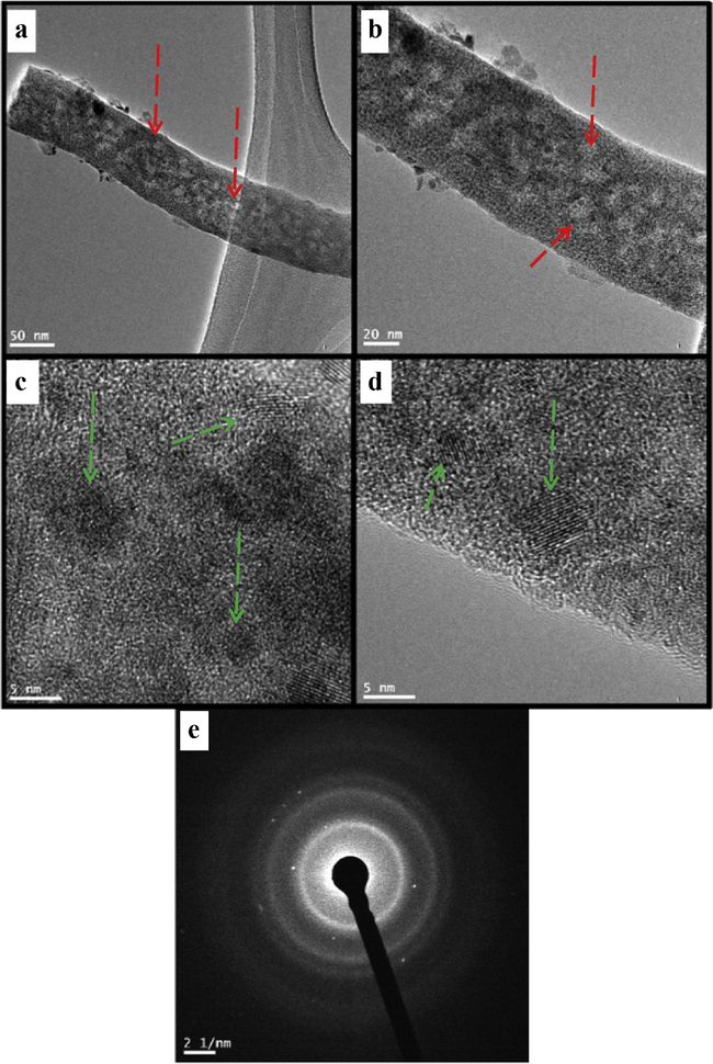
TEM (a and b) HRTEM image (c and d) and SEAD image (e) of produced nanofibers after calcination.
Figs. 6 and 7 show TEM mapping and Line-EDX analyses, respectively. Fig. 6. The TEM-mapping analyses indicate that carbon is the main element, and Zn, Ce and O are well dispersed on the obtained nanofibers. In addition, the Line-EDX analysis (Fig. 7) further conforms that the sample contains C, O, Zn and Ce; no other elemental impurities are detected. Moreover, the same elemental distributions are observed along with the randomly chosen line.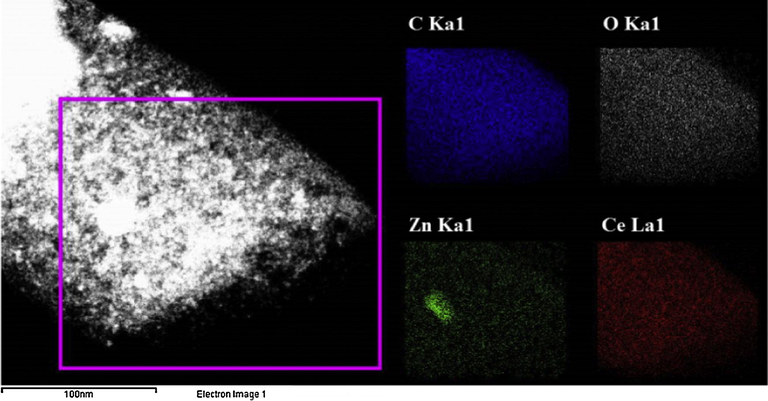
Elemental mapping for the obtained ZnO(40%)CeO2(60%) nanodots@CNFs after calcination at 700 °C for 7 h in argon atmosphere.
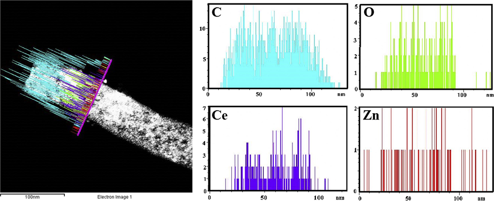
Line TEM EDX, analysis of produced ZnO(40%)CeO2(60%) nanodots@CNFs after calcination at 700 °C for 7 h in argon atmosphere.
In conclusion, the invoked characterizations techniques indicated novel morphology which might improve the electrocatalytic activity. Furthermore, it can be appealed that the synthesized nanostructure is ZnO(40%)CeO2(60%) nanodots@CNFs.
Fig. 8(a and b) shows the cyclic voltammetric performance in alkaline media (1.0 M KOH) of two proposed nanofibrous composites (ZeO(40%)CeO2(60%) and ZeO(60%)CeO2(40%) nanodots@CNFs). As shown in the figure polarization was started by a potential scanning at a scan rate of 50 mV/s from 1000 mV to −200 mV (vs. Ag/AgCl reference electrode) in the cathodic direction and then the scan was reversed in the anodic direction back to 1000 mV.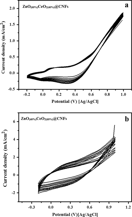
Cyclic voltammograms of the carbon nanofibers containing ZnO(60%)CeO2(40%) (a) and ZnO(40%)CeO2(60%) (b) formulations in 1 M KOH. Scan rate 50 mV/s.
As revealed in Fig. 8(a), the performance of the nanofibrous composite having 60 wt% ZnO, two pairs of redox peaks can be experiential; while as shown in Fig. 8(b), decreasing the ZnO content in the nanofibrous composite led to virtually vanishing of these peaks which specifies that the performance of nanofibrous composite does not depend on the formation of OOH2− ionic layers on the surface of the active material (Barakat et al., 2014b; Barakat and Motlak, 2014b; Barakat et al., 2014a; Ghouri et al., 2015c). Increasing the number of potential sweeps effects in progressive increase of the current density value due to entrance of OH− ions into the surface of catalyst. Furthermore, considerable difference in the corresponding current densities of the two formulations is also observed; ZeO(40%)CeO2(60%) nanodots@CNFs reveals relatively higher values. It is well known that the metallic oxides composition intensely disturbs the physicochemical characteristics (Barakat et al., 2014b,a); hence cyclic voltammetry (CV) method was applied to investigate the electro-oxidation of methanol in alkaline media.
The CV curves of ZeO(40%)CeO2(60%) and ZeO(60%)CeO2(40%) nanodots@CNFs in 3 M methanol (in 1 M KOH) solution were noted at the scan rate of 50 mV/s at 25 °C.
Fig. 9 displays the influence of the composition of the metallic oxide NPs on the electro-catalytic activity. As shown in the figure, the ZnO content has very strong impact on electrooxidation of methanol, additionally a strong impact of the CeO2 doping with 40% ZnO NPs electrode on the current densities can be experiential, as shown in the figure ZnO(40%)CeO2(60%) nanodots@CNFs revealed the best performance in electrooxidation of methanol. Fig. 10 illustrates the influence of methanol concentration on the attained current density. As depicted in the figure (a and b), both formulations (ZeO(40%)CeO2(60%) and ZeO(60%)CeO2(40%)) are sensitive to methanol addition; as current densities are increased with the increase of methanol concentration; indicates methanol oxidation on the surface of the nanofibrous composite (Barakat and Motlak, 2014b; Ghouri et al., 2015c). Table 1. summarizes the important information embedded in Fig. 10(a and b).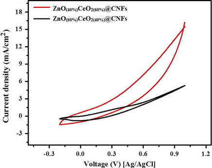
Study the influence of ZnO and CeO2 percentage on the electrocatalytic activity of the prepared CNFs containing (ZnO(40%)CeO2(60%) and ZnO(60%)CeO2(40%)) toward methanol oxidation (3 M methanol + 1 M KOH) at scan rate 50 mV/s at 25 °C.
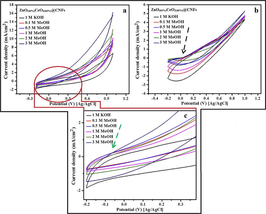
Typical cyclic voltammogram of the carbon nanofibers containing ZnO(40%)CeO2(60%) (a) and ZnO(60%)CeO2(40%) (b) formulations in different concentrations of methanol (+1 M KOH) and high magnification (c) to show the onset potential at scan rate 50 mV/s at 25 °C.
ZeO(40%)CeO2(60%)@CNFs
ZeO(60%)CeO2(40%)@CNFs
Conc. of MeOH (M)
0.0
0.1
0.5
1.0
2.0
3.0
0.0
0.1
0.5
1.0
2.0
3.0
Current density (mA/cm2)
6.4
8.4
9.4
10.0
11.9
16.3
4.3
4.6
4.8
4.8
4.4
5.3
The onset potential is key factor among the invoked parameters to demonstrate the electrocatalytic activity because it can be utilized to evaluate the efficacy of the catalyst; basically onset potential is the indicator for electrode over potential, because onset potential at which the given electrode can produce a reasonable amount of target gas molecules (Barakat and Motlak, 2014b; Barakat et al., 2014a).
As shown in Fig. 10(c), the onset potential for methanol oxidation was observed at −50 mV (vs. Ag/AgCl) shown by light green arrow, and the acquired onset potential is reasonably very low compared to many reported materials (Barakat et al., 2014a; Ghouri et al., 2015c). Concerning ZeO(60%)CeO2(40%) nanodots@CNFs sample, it has a corresponding onset potential of 30 mV [vs. Ag/AgCl] which is also small compared to many reported non-precious electrocatalysts, shown by black arrow (Fig. 10(b)). This discovery additionally supports the electrocatalytic performance of the introduced nanofibers.
Electrochemical impedance spectroscopy (EIS) is an influential diagnostic tool to illustrate the performance of fuel cell and was performed to observe the methanol oxidation in alkaline medium. Fig. 11 shows the distinctive Nyquist graph for ZeO(40%)CeO2(60%) nanodots@CNFs sample in various concentrations of methanol in alkaline condition.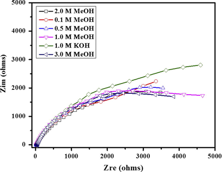
Nyquist plot of ZnO(40%)CeO2(60%) nanodots@CNFs at different concentrations of methanol.
Inconsequential effect of methanol addition was observed on the Nyquist plot; moreover, lower charge transfer resistance is observed at higher concentration of methanol.
Chronoamperometry is very powerful method for the qualitative analysis of electrocatalyst in alkaline or acidic medium, Fig. 12 illustrates the chronoamperometric analysis of ZnO(40%)CeO2(60%) nanodots@CNFs and Co/SrCO3@CNFs based electrodes recorded for 500s at constant anodic potential (0.4 V) in 3 M methanol (+1 M KOH) at room temperature. Compared to Co/SrCO3@CNFs based electrode the ZnO(40%)CeO2(60%) nanodots@CNFs based electrode showed higher current density in the entire measurement but on the other hand current decay rate is quite higher than that of Co/SrCO3@CNFs based electrode and with the passage of time electrooxidation process initially decreases and approaches consistency.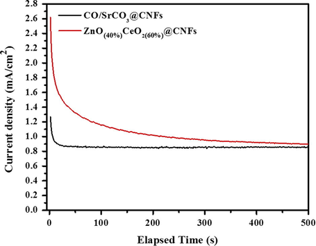
Chronamperometery for ZnO(40%)CeO2(60%) nanodots@CNFs electrode at V = 0.4 V vs. Ag/AgCl in 3 M methanol in alkaline medium.
Remarkably, single electrode has been employed in all electrochemical characterization without any obvious deformation which supports the good constancy of the presented electrocatalyst.
4 Conclusion
It is well known nanodots with small dot size guarantee high catalytic activity, while high dot density can provide a basis for reducing devices and increasing performance activity. Effective electrocatalyst can be fabricated by using ZnAc and CeAc as the active electrode material. The size of ZnO/CeO2 nanodots was very small (4 nm) with high dispersion on the surface of CNFs which can be considered an advantageous in catalysis. Consequently, ZnO(40%)CeO2(60%) nanodots decoration on CNFs surface significantly enhanced the electrocatalytic activity of methanol, signifying an auspicious candidate for the DMFCs application. Remarkably, ZnO(40%)CeO2(60%) nanodots@CNFs-based electrode exhibited small onset potential (−50 mV/s). More importantly, methanol oxidation takes place at relatively low applied voltage (250 mV). Generally, it can be appealed that the ZnO(40%)CeO2(60%) nanodots@CNFs might be a new promised non-precious electrocatalyst for DMFCs applications.
Acknowledgments
This Research was financially supported by National Research Foundation of Korea (NRF) Grant funded by the Korean Government (MSIP) (No. 2014R1A4A1008140) and Basic Science Research Program through the National Research Foundation of Korea (NRF) funded by the Ministry of Education (No. NRF-2014R1A1A2008489).
References
- Nematic shaped Cadmium sulfide doped electrospun nanofiber mat: highly efficient, reusable, solar light photocatalyst. Colloids Surf. A: Physicochem. Eng. Aspects. 2012;409:21-29.
- [Google Scholar]
- Composite polymer core–ceria shell abrasive particles during oxide cmp: a defectivity study. J. Electrochem. Soc.. 2008;155(9):H653-H660.
- [Google Scholar]
- CoxNiy-decorated graphene as novel, stable and super effective non-precious electro-catalyst for methanol oxidation. Appl. Catal. B: Environ.. 2014;154:221-231.
- [Google Scholar]
- CoxNiy-decorated graphene as novel, stable and super effective non-precious electro-catalyst for methanol oxidation. Appl. Catal. B: Environ.. 2014;154–155:221-231.
- [CrossRef] [Google Scholar]
- Cobalt nanofibers encapsulated in a graphite shell by an electrospinning process. J. Mater. Chem.. 2009;19(39):7371-7378.
- [Google Scholar]
- CoNi bimetallic nanofibers by electrospinning: nickel-based soft magnetic material with improved magnetic properties. J. Phys. Chem. C. 2010;114(37):15589-15593.
- [Google Scholar]
- Cobalt/copper-decorated carbon nanofibers as novel non-precious electrocatalyst for methanol electrooxidation. Nanoscale Res Lett. 2014;9(2):1-10.
- [Google Scholar]
- NixCo1-x alloy nanoparticle-doped carbon nanofibers as effective non-precious catalyst for ethanol oxidation. Int. J. Hydr. Energy. 2014;39(1):305-316.
- [CrossRef] [Google Scholar]
- Carbon nanofibers doped by NixCo1−x alloy nanoparticles as effective and stable non precious electrocatalyst for methanol oxidation in alkaline media. J. Mol. Catal. A: Chem.. 2014;394:177-187.
- [CrossRef] [Google Scholar]
- Oxygen gas sensors based on CeO2 thick and thin films. Sens. Actuat. B: Chem.. 1991;4(3–4):393-399.
- [CrossRef] [Google Scholar]
- Electrical energy storage for the grid: a battery of choices. Science. 2011;334(6058):928-935.
- [CrossRef] [Google Scholar]
- Spinning continuous fibers for nanotechnology. Science. 2004;304(5679):1917-1919.
- [CrossRef] [Google Scholar]
- Converting ceria polyhedral nanoparticles into single-crystal nanospheres. Science. 2006;312(5779):1504-1508.
- [Google Scholar]
- Nanostructured Au–CeO2 catalysts for low-temperature water-gas shift. Catal. Lett.. 2001;77(1–3):87-95.
- [CrossRef] [Google Scholar]
- Active nonmetallic Au and Pt species on ceria-based water-gas shift catalysts. Science. 2003;301(5635):935-938.
- [CrossRef] [Google Scholar]
- Facile synthesis of Fe/CeO2-doped CNFs and their capacitance behavior. Int. J. Electrochem. Sci.. 2015;10:2064-2071.
- [Google Scholar]
- Synthesis and characterization of Co/SrCO3 nanorods-decorated carbon nanofibers as novel electrocatalyst for methanol oxidation in alkaline medium. Ceram. Int.. 2015;39(1):6575-7582.
- [Google Scholar]
- Co/CeO2-decorated carbon nanofibers as effective non-precious electro-catalyst for fuel cells application in alkaline medium. Ceram. Int.. 2015;41(2, Part A):2271-2278.
- [CrossRef] [Google Scholar]
- Electrospinning: a fascinating method for the preparation of ultrathin fibers. Angewandte Chemie Int. Ed.. 2007;46(30):5670-5703.
- [CrossRef] [Google Scholar]
- Cleaning the air and improving health with hydrogen fuel-cell vehicles. Science. 2005;308(5730):1901-1905.
- [CrossRef] [Google Scholar]
- Nanocrystalline undoped ceria oxygen sensor. Sens. Actuat. B: Chem.. 2003;95(1):73-77.
- [Google Scholar]
- Use of CeO2-based oxides in the three-way catalysis. Catal. Today. 1999;50(2):285-298.
- [Google Scholar]
- Preparation and characterization of multiwalled carbon nanotube-supported platinum for cathode catalysts of direct methanol fuel cells. J. Phys. Chem. B. 2003;107(26):6292-6299.
- [Google Scholar]
- An oxygen reduction electrocatalyst based on carbon nanotube-graphene complexes. Nat. Nano. 2012;7(6):394-400. http://www.nature.com/nnano/journal/v7/n6/abs/nnano.2012.72.html#supplementary-information
- [Google Scholar]
- Ti-doped SnOx encapsulated in Carbon nanofibers with enhanced lithium storage properties. Electrochim. Acta. 2014;137:9-16.
- [Google Scholar]
- Electrochemical capacitors for energy management. Science. 2008;321(5889):651-652.
- [CrossRef] [Google Scholar]
- Direct oxidation of hydrocarbons in a solid-oxide fuel cell. Nature. 2000;404(6775):265-267.
- [Google Scholar]
- Characteristics of e-beam deposited electrochromic CeO2 thin films. Solid State Ionics. 2003;165(1):131-137.
- [Google Scholar]
- Comparison of oxygen reduction reaction at silver nanoparticles and polycrystalline silver electrodes in alkaline solution. J. Phys. Chem. C. 2012;116(19):10656-10663.
- [CrossRef] [Google Scholar]
- Investigation of Pd-based electrocatalysts for oxygen reduction in PEMFCs operating under automotive conditions. J. Power Sources. 2013;222:390-399.
- [CrossRef] [Google Scholar]
- A Pt-Ru/graphitic carbon nanofiber nanocomposite exhibiting high relative performance as a direct-methanol fuel cell anode catalyst. J. Phys. Chem. B. 2001;105(34):8097-8101.
- [Google Scholar]
- Solid-electrolyte membrane reactors: current experience and future outlook. Catal. Rev.. 2000;42(1–2):1-70.
- [Google Scholar]
- Recent anode advances in solid oxide fuel cells. J. Power Sources. 2007;171(2):247-260.
- [Google Scholar]
- Cathode materials for solid oxide fuel cells: a review. J. Solid State Electrochem.. 2009;14(7):1125-1144.
- [Google Scholar]
- Catalytic properties of ceria and CeO2-containing materials. Catal. Rev.. 1996;38(4):439-520.
- [CrossRef] [Google Scholar]
- Proton exchange membrane fuel cells with carbon nanotube based electrodes. Nano Lett.. 2004;4(2):345-348.
- [CrossRef] [Google Scholar]
- A review of polymer electrolyte membrane fuel cells: technology, applications, and needs on fundamental research. Appl. Energy. 2011;88(4):981-1007.
- [CrossRef] [Google Scholar]
- The lanthanides, rare earth metals. In: Patty’s Toxicology. John Wiley & Sons, Inc.; 2001.
- [CrossRef] [Google Scholar]
- Effects of structural patterns and degree of crystallinity on the performance of nanostructured ZnO as anode material for lithium-ion batteries. J. Alloys Compd.. 2015;627:455-462.
- [CrossRef] [Google Scholar]
- Nitrogen/phosphorus co-doped nonporous carbon nanofibers for high-performance supercapacitors. J. Power Sources. 2014;248:745-751.
- [Google Scholar]
- Oxygen permeation through the LSCO-80/CeO2 asymmetric tubular membrane reactor. J. Membr. Sci.. 2006;268(1):2-12.
- [CrossRef] [Google Scholar]
- Synthesis and electrochemical properties of MnO2 and co-decorated graphene as novel nanocomposite for electrochemical super capacitors application. Energy Environ Focus. 2015;4(1):34-39.
- [Google Scholar]
- Iron phthalocyanine and nitrogen-doped graphene composite as a novel non-precious catalyst for the oxygen reduction reaction. Nanoscale. 2012;4(23):7326-7329.
- [CrossRef] [Google Scholar]
- Electrospun TiC/C nano-felt surface-decorated with Pt nanoparticles as highly efficient and cost-effective counter electrode for dye-sensitized solar cells. Nanoscale. 2013;5(23):11742-11747.
- [CrossRef] [Google Scholar]


