

Translate this page into:
Novel composite in situ obtained from coal gasification coarse slag and its mechanism of removing phosphate
⁎Corresponding authors. yl.li@cug.edu.cn (Yilian Li), 625477897@qq.com (Fenglan Han), byd1975@163.com (Yadong Bai)
-
Received: ,
Accepted: ,
This article was originally published by Elsevier and was migrated to Scientific Scholar after the change of Publisher.
Peer review under responsibility of King Saud University.
Abstract
A novel low-cost hematite–silicon mesoporous composite (HSMC) was synthesized in situ from coal gasification coarse slag (CGCS) via acid modification and its potential for phosphate removal from wastewater was studied. Calcium, aluminum and iron in CGCS were activated by hydrochloric acid, and formed crystalline hematite on the quartz and silicates substrates. Compared with traditional methods of preparing hematite, this in-situ preparation method effectively utilized the iron in CGCS instead of requiring added iron salts, which is highly cost-effective. The specific surface area increased from 4 m2/g for CGCS to 67 m2/g for HSMC, greatly enhancing the phosphate removal ability of HSMC. The maximum adsorption capacity of HSMC for phosphate was 28.62 mg/g, which is more than 28 times higher than that of CGCS. The HSMC had a high point of zero charge (pHPZC) of 7.5, providing good phosphate removal performance over a wide pH range. The phosphate removal mechanism of HSMC mainly involves ligand exchange induced by the large number of hydroxyl groups, inner-sphere complexation induced by the presence of major metal (hydr)oxides, the precipitation of calcium and aluminum with phosphate groups, and some electrostatic adsorption induced by the positively charged surface. The contribution of precipitation to the phosphate removal ability was approximately 27 %. This study provides a new method for the development of phosphate adsorbents while recycling CGCS.
Keywords
Recycle
Solid waste
Wastewater
Adsorption
Desorption

1 Introduction
Coal gasification coarse slag (CGCS) is a kind of coal gasification slag (CGS), the other is coal gasification fine slag (CGFS), they are both solid wastes produced during coal gasification. Unlike CGFS, which is discharged by air flow at the top of the furnace, CGCS is discharged from the bottom lock hopper of the gasification furnace (Liu et al., 2019). With the rapid development of coal gasification technology in China, approximately 20–26 million tons of CGCS is produced annually (Qu et al., 2020). CGCS storage requires large area of land and poses potential risks to the surrounding environment. Therefore, there is an urgent need to develop CGCS utilization technologies.
Both CGCS and CGFS contain large amounts of silica and metal (Ca, Al, and Fe) oxides. Accordingly, most studies on CGS utilization technologies use acids to leach these elements and prepare different porous materials from CGS (Yuan et al., 2022). Liu et al. (Liu et al., 2019) used acids to leach metal oxides in CGFS and calcined them to obtain mesoporous materials. The concentration of hydrochloric acid (HCl), rather than the activity of the metal oxides, was the main factor affecting the leaching rate. Zhu et al. (Zhu et al., 2020) prepared a carbon–silica mesoporous composite in situ using CGFS as a raw material by HCl leaching. The dissolution of the metal oxides started from the surface of the silica glass microspheres and formed dendritic mesoporous channels. Several studies have been conducted on the removal of metal oxides from CGS as impurities (Wu et al., 2020; Zhang et al., 2020a; Zhang et al., 2020b; Zhang et al., 2021). Currently, research on recycling CGS mainly employs acid leaching to remove metal oxides impurities. However, this constitutes a waste of resources and causes a risk of secondary environmental pollution. Metal (hydr)oxides are known to be effective for phosphate removal (Li et al., 2016). Despite this, the use of metal oxides from CGS for phosphate removal has not yet been reported. In addition, most studies on the utilization of CGS have focused on CGFS, with few related studies on CGCS. This study makes full use of the metal components in the CGCS for the first time to remove phosphate. Unlike the traditional preparation of mesoporous materials from CGS, in which the metal components were removed as impurities. We obtained mesoporous materials from CGCS without removing the metal components, which maximizes the resource utilization of the CGS and avoids the waste of metal components in CGS.
Herein, a novel low-cost hematite–silicon mesoporous composite (HSMC) was prepared in situ by impregnating CGCS with acid and calcining. Unlike traditional methods of preparing hematite-supported substrates, this study did not involve the introduction of additional iron salts; instead, the iron in CGCS was fully utilized to produce hematite, which has good economic benefits. Therefore, this study proposed a new method of CGCS recycling. We investigated the formation mechanism of HSMC, the removal performance of phosphates by HSMC, and the mechanism of phosphate removal, which have not been studied before. This study provides a new candidate for the recycling of CGCS and the removal of phosphates from wastewater, which has important economic and environmental benefits.
2 Materials and method
2.1 Materials
CGCS was obtained from the Shenhua Ning Coal Group in Ningxia, China. The CGCS was ground and passed through a 60-mesh sieve. Its chemical composition is listed in Table S1. Potassium dihydrogen phosphate, potassium tartrate semihydrate and hexaammonium heptamolybdate tetrahydrate were purchased from Tianjin Kemiou, China. HCl and NaOH were purchased from Sinopharm Group. All reagents used in this study were of analytical grade.
2.2 Preparation of materials
CGCS (5 g) was added to a 250 mL conical flask containing 25 mL of 14 % HCl. The mixture was magnetically stirred for 4 h at 50 °C and 300 rpm. It was then dried at 120 °C to remove water and residual acid. The resultant intermediate was fed into a muffle furnace and burned at 500 °C for 4.5 h to obtain HSMC. Finally, the HSMC was washed with deionized water, dried at 100 °C in a thermostatic drying oven, ground, and stored in a desiccator for subsequent experiments.
2.3 Characterizations
The chemical composition of the CGCS before and after acid immersion and washing with water was determined using X-ray fluorescence (XRF) measurements (Panalytical Axios, Nether-lands). The microstructure and elemental distribution of the HSMC were explored using scanning electron microscopy and energy dispersive spectroscopy (SEM-EDS; Zeiss Gemini 300, Germany). The functional groups of CGCS, HSMC, and other related samples were examined using Fourier-transform infrared spectrometry (FTIR; Thermo Scientific Nicolet 6700, USA) within the 400–4000 cm−1 range. X-ray diffraction (XRD; LabX XRD-6000, Japan) was used to obtain the crystal characteristics of the HSMC and other related samples using Cu Kα radiation (40 kV, 30 mA) at a rate of 2°/min in a scan range of 10–80°. X-ray photoelectron spectroscopy (XPS; Thermo Scientific K-Alpha, USA) was used to determine the elemental composition and binding energy. The point of zero charge (pHPZC) of the HSMC was examined according to the pH drift method [9]. The Brunauer–Emmett–Teller (BET) specific surface area and pore size were deter-mined by N2 adsorption using a BET surface area analyzer (3H-2000PM1, China).
2.4 Batch experiments
Batch adsorption tests were conducted by adding 50 mg of HSMC to 50 mL of a 40 mg/L phosphate solution in a 250 mL conical flask and reacting in an oscillator (150 rpm) for 24 h at 28 °C. After the adsorption reaction, the mixture was centrifuged and the phosphate content in the supernatant was determined using the molybdenum antimony anti-spectrophotometric method at a detection wavelength of 710 nm with ultraviolet–visible spectrophotometer (PERSEE TU-1901, China). The adsorption capacity q (mg/g) is computed according to the following equation (Abdellaoui et al., 2021):
The influence of pH on the phosphate removal ability was studied within a pH range of 3–10, which was adjusted using 0.1 M HCl or NaOH. The effects of competitive anions and humic acid (HA) on phosphate removal were examined using two different concentrations of ionic solutions (NaCl, NaNO3, Na2SO4, and NaHCO3; 2 and 20 mM) and HA solutions (40 and 80 mg/L). Phosphate adsorption isotherms were obtained using different initial phosphate concentrations (5–80 mg/L). The adsorption kinetics were evaluated by taking samples after different reaction times (0.5–38 h) to analyze the residual phosphate concentration. All the tests described above were conducted in triplicate. All experiments were conducted three times, and the standard deviations were within the range of 0–1.
2.5 Reusability experiments
HSMC reusability tests were performed for four cycles by adding 50 mg of HSMC to 50 mL of a 40 mg/L phosphate solution and reacting for 24 h at 28 °C. After adsorption, the HSMC was mixed with 50 mL of 1 M NaOH and reacted for 24 h at 28 °C, after which it was washed with deionized water until neutral and dried for the next adsorption–desorption cycle.
2.6 Column adsorption tests
Continuous flow tests were conducted using simulated wastewater and actual wastewater (lake water) to assess the practical phosphate removal performance of the HSMC. lake water was collected from a lake in Yinchuan (Ningxia, China) in August 2022. The tests were performed in an organic glass tube with an inner diameter of 12 mm and length of 130 mm. The upper and lower ends of the tube were blocked with degreasing cotton balls to prevent sample loss, and 2.5 g of HSMC (about 2.5 cm bed height) was placed between the cotton balls. The actual phosphate concentration in the lake water was low (0.04 mg/L); similarly, the phosphate concentration in most surface water is low. However, to better observe the phosphate removal performance during continuous flow experiments, the phosphate concentration of the lake water was adjusted to 2 mg/L. The flow rate was controlled at 1 mL/min using a peristaltic pump (Rongbai BT 100). The treated water was collected in a 10 mL centrifuge tube at the outlet, and the phosphate concentration was measured.
2.7 Leaching test
The release of Ca, Al, Fe, and major heavy metal ions from the HSMC in deionized water and the contents of Ca, Al, and Fe in phosphate solutions were detected as follows. HSMC (0.05 g) was added to 50 mL of deionized water, adjusted to pH 6, and shaken in a water bath oscillator (150 rpm) for 24 h at 28 °C. Leaching tests were also conducted in phosphate solution by the same method.
3 Results and discussion
3.1 Characterization
The chemical composition of the CGCS was analyzed by XRF before and after acid leaching and water washing (denoted as CGCS-H-W). The results are shown in Table S1. The Fe, Ca, and Al contents in the CGCS-H-W sample were significantly lower than those in the initial CGCS sample, indicating that Fe, Ca, and Al were activated and leached by HCl. In addition, the content of Al was slightly higher in HSMC than in CGCS, while the contents of Fe and Ca were slightly lower, leading to slight reduction in the overall Fe + Ca + Al content. This indicates that the contents of Fe, Ca, and Al have changed during the formation of HSMC.
SEM-EDS analysis was performed to explore the changes in the morphology and phase composition of the HSMC after phosphate removal, HSMC, and CGCS (Fig. 1). The CGCS had a block structure with a rough surface and holes of different sizes. After acid leaching and calcination, regular sheet-like structures were formed on the surface of the HSMC. These sheet-like structures are stacked, with several holes between them. Combined with the XRD analysis results, the sheet-like structure may be hematite. In addition, cotton-ball-like substances were observed, which may be amorphous alumina and calcium hydroxide, according to the FTIR and XPS results. The EDS spectrum corresponded to the position of the cross cursor in the SEM image. Comparison of Fig. 1d and e shows that the content of metal elements, such as Ca and Fe, in CGCS decreases, while the Al content increases, indicating that the main metal elements were activated by the acid during acid leaching and underwent material reorganization during the roasting process, with the new substances formed in situ. After the reaction between HSMC and phosphate, flocculent substances appeared on the surface of the HSMC (Fig. 1c). Peaks corresponding to phosphate were present in the EDS spectrum (Fig. 1f), which demonstrates that these flocculent substances are related to phosphate. Thus, the HSMC successfully captured phosphate.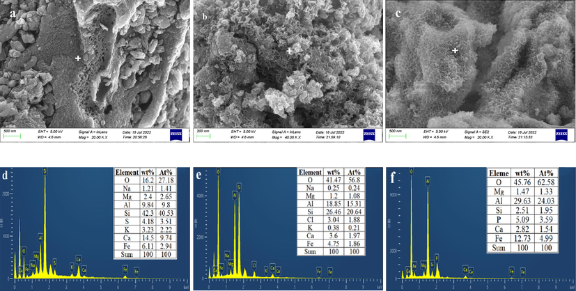
SEM and EDS spectra of CGCS (a,d), HSMC (b,e) and HSMC after phosphate adsorption (c,f).
To explore the specific surface area and pore size distribution of the HSMC and CGCS samples, N2 adsorption–desorption isotherms and Barrett–Joyner–Halenda (BJH) pore size distribution analyses were carried out, and the results are shown in Fig. S1 and Table S2. Both CGCS and HSMC exhibited type-IV isotherms and H3 hysteresis loops (Fig. S1a) according to the IUPAC definition (Thommes et al., 2015). This indicates the existence of slit-like pores, such as those that form between stacked plate-like particles (Zhou et al., 2011; Zhu et al., 2021).
Fig. S1b shows that the HSMC and CGCS samples are mainly mesoporous materials. The pore size of HSMC was mainly concentrated in the range of 3–4 nm, and that of CGCS was mainly concentrated at 2–4 nm. The mesoporous content in the HSMC sample was 35 times greater than that of the CGCS. This indicates that the HCl impregnation and calcination resulted in the formation of a large number of mesopores in the HSMC. The increase in the number of mesopores increased the specific surface area from 4 m2/g for CGCS to 67 m2/g for HSMC. These changes are beneficial for improving the phosphate adsorption capacity.
3.2 Phosphate adsorption
3.2.1 Effect of pH
As shown in Fig. 2, the amount of adsorbed phosphate showed little change with the pH of the wastewater, except at pH 3. Acidic conditions are more conducive to the removal of phosphate by HSMC; therefore, the amount of adsorbed phosphate was slightly lower under alkaline conditions. However, even in an alkaline environment (pH 10), the HSMC sample still had a phosphate adsorption amount of approximately 18 mg/g. This shows that HSMC is applicable over a wide pH range.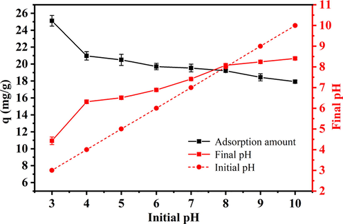
Effect of wastewater pH on phosphate adsorption capacities of HSMC. Adsorption conditions: reaction time, 24 h; sorbent dose, 1.0 g/L; temperature, 28 ℃; initial phosphate concentration, 40 mg/L.
As presented in Text S1, at pH values of 3–10, phosphates were mainly present in the form of H2PO4− and HPO4−. The pHPZC of HSMC was 7.5 (shown in Part 3.1.1). Therefore, when the pH of the wastewater was less than (or more than) 7.5, the surface of HSMC was positively (or negatively) charged (Asaoka et al., 2021; Yu et al., 2015). Under neutral and acidic conditions, the surface of HSMC was protonated and positively charged. This facilitates strong electrostatic adsorption between the HSMC surface and the H2PO4− and HPO4− ions, leading to a relatively large phosphate adsorption amount. A high pHPZC value enables HSMC to maintain a good phosphate adsorption capacity over a wide pH range (3–7). Under alkaline conditions, the surface of HSMC was deprotonated and negatively charged, indicating that the electrostatic adsorption was weakened and the phosphate adsorption capacity was reduced. In addition, under alkaline conditions, OH− ions competed with phosphate ions for the binding sites on HSMC, which further reduced the phosphate adsorption capacity.
Notably, the final pH increased within the initial pH in the range of 3–8. This change occurred because of ligand exchange between the hydroxyl groups on the HSMC surface and the phosphate ions in the wastewater, which released large amounts of hydroxide ions into the wastewater, increasing the OH− concentration and pH (Liao et al., 2018). In summary, ligand exchange and electrostatic adsorption are the mechanisms of phosphate removal by HSMC.
3.2.2 Effects of competitive anions and humic acid
Competing anions, such as Cl−, HCO3−, NO3−, and SO42−, and organic compounds, such as HA, are ubiquitous in water and usually interfere with the adsorption of phosphates by adsorbents. Hence, the effects of these substances on the phosphate adsorption capacity of HSMC were investigated, and the results are illustrated in Fig. 3. Except for a slight negative effect of HCO3− and HA, the other competing anions had almost no negative effect on the amount of adsorbed phosphate. This shows that HSMC has good selective adsorption of phosphate. This phenomenon may be related to the inner-sphere complexes formed between the HSMC particles and phosphates. The outer-sphere associations formed by electrostatic interactions are highly sensitive to the concentration of anions, whereas the inner-sphere complexes formed by ligand exchange tend to be insensitive to the concentrations of coexisting anions (Min et al., 2019). The negative effect of HCO3− on phosphate adsorption may be because HCO3− has a similar structure to H2PO4− and HPO4− and can form inner-sphere complexes to compete with phosphate for the binding sites on HSMC (Shi et al., 2019).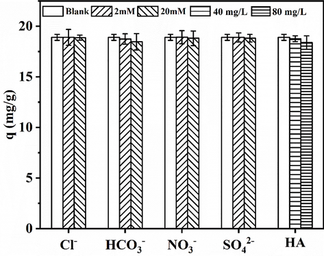
Effects of competitive anions and humic acid on phosphate adsorption by HSMC. Adsorption conditions: reaction time, 24 h; sorbent dose, 1.0 g/L; temperature, 28 ℃; pH, 6; initial phosphate concentration, 40 mg/L.
Humic acid is a macromolecular natural organic substance with active carboxyl, hydroxyl, and carbonyl groups. Its negative effect on phosphate adsorption by HSMC may be related to the competition between these active groups and phosphate ions for the binding sites on HSMC. In addition, macromolecular HA may block the mesopores or micropores of HSMC and block the binding of phosphate ions to the active sites in the pores.
3.2.3 Adsorption isotherms
To evaluate the phosphate adsorption performance of HSMC, an isothermal experiment was conducted, and the experimental data and isotherm model fitting results are presented in Fig. 4 and Table S3. The Langmuir and Freundlich non-linear equations can be expressed as follows (Sewu et al., 2017):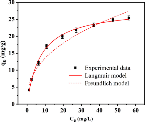
Phosphate adsorption isotherm on HSMC. Adsorption conditions: temperature, 28 ℃; pH, 6; initial phosphate concentration, 5–80 mg/L.
Langmuir isotherm equation:
Freundlich isotherm equation:
Where Ce (mg/L) represents the phosphate concentration at the equilibrium stage of sorption, qe and qm represents the sorption amounts of phosphate by HSMC at equilibrium and the theoretical maximum monolayer sorption capacity, respectively, KL refers to the Langmuir constant, and measures the sorbent affinity to the solute. KF is the adsorption coefficient.
Compared with the Freundlich model, the Langmuir isotherm model is in better agreement with the experimental data, and the fitting coefficient (R2) was 0.997. Thus, the surface of the HSMC particles is likely to be homogeneous, with the adsorption of phosphates occurring by monolayer adsorption (Koh et al., 2020). The maximum phosphate adsorption capacity calculated by the Langmuir isotherm model was 28.62 mg/g, indicating that the HSMC has good phosphate removal capacity. Notably, the phosphate removal capacity was considerably larger than those of other reported adsorbents (Table S4).
3.2.4 Adsorption kinetic studies
To explore the phosphate adsorption process, a kinetic study was performed. Three kinetic models were used to analyze the kinetic experimental data, and the analysis results are shown in Fig. 5 and Table S5. The non-linear equations of the three common kinetic models can be displayed below (Akram et al., 2017; Liang et al., 2018):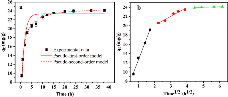
Adsorption kinetics plots fitted with (a) pseudo-first-order, pseudo-second-order model, and (b) intraparticle diffusion models. Adsorption conditions: temperature, 28 ℃, pH 6; adsorbent dose, 1.0 g/L; initial phosphate concentration, 40 mg/L.
The pseudo first order equation:
The pseudo second order equation:
The intraparticle diffusion model:
The pseudo-second-order model described the adsorption process better than the pseudo-first-order model, with correlation coefficients (R2) of 0.996 and 0.942, respectively. In addition, the calculated equilibrium adsorption capacity of the pseudo-second-order model (24.77 mg/g) was closer to the experimental data (24.22 mg/g). This indicated that the overall phosphate adsorption rate was mainly controlled by chemisorption (Jung et al., 2019).
To further determine the rate-controlling step of phosphate adsorption by HSMC, an intraparticle diffusion model was introduced to interpret the experimental data and further illustrate the diffusion mechanism. As illustrated in Fig. 5b, the fitting line contains three straight lines, representing the three adsorption stages. The first stage represents membrane diffusion or boundary layer rapid transport of phosphate ions from the bulk solution to the HSMC surface. The second stage corresponds to intraparticle diffusion or pore diffusion of phosphate ions from the external surface of the HSMC to the internal adsorption sites. Finally, the third stage is the adsorption equilibrium stage. The second line segment does not pass through the coordinate origin, and the intercept C ≠ 0 (Table S5), indicating that the adsorption rate is determined by a multistage rate-controlling step rather than the intraparticle diffusion (Konicki et al., 2017). The slope (rate constant) of the first line is greater than that of the second line (kid1 > kid2), indicating that the boundary layer transport or membrane diffusion rate is the primary rate-limiting step, and intraparticle diffusion is the secondary rate-limiting step (Jung et al., 2019).
3.2.5 Reusability
To evaluate the reusability of the HSMC sample, four adsorption–desorption cycles were performed using the same sample, and the results are shown in Fig. 6. With an increase in the cycle number, the phosphate adsorption capacity of HSMC decreased. After four cycles, the amount of adsorbed phosphate decreased from 19.63 to 12.48 mg/g. This may be related to the inner-sphere complexes formed between the phosphate ions and HSMC, which are more difficult to desorb than physically adsorbed phosphate ions (Huang et al., 2020). In addition, according to the results of the metal ion leaching experiment in Section 3.2.6, a small number of Ca ions were lost when the HSMC was washed with water, which would reduce the effective components for phosphate removal and further affect the phosphate adsorption capacity of recycled HSMC. Nevertheless, the HSMC can be reused for at least four cycles.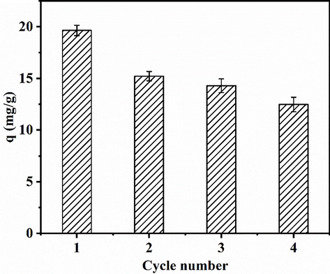
Relationship between the adsorption capacity of HSMC and the cycle number. Adsorption conditions: temperature, 28 ℃; pH, 6; adsorbent dose, 1.0 g/L; eluant, 1 M NaOH; initial phosphate concentration, 40 mg/L.
3.2.6 Metal leaching
To explore whether HSMC causes secondary harm to the environment during the phosphate removal process, heavy metal leaching experiments were carried out in deionized water, and Ca, Al, and Fe leaching experiments were conducted in deionized water and phosphate solution for comparison. As shown in Table 1, the amounts of heavy metals leached from HSMC were all lower than the concentration limit of Class I surface water in China’s surface water environmental quality standards (GB 3838–2002). This proves that HSMC is safe and does not cause secondary pollution. Comparing the leaching results of Ca, Al, and Fe in deionized water and phosphate solution after phosphate removal (Table S6) demonstrated that a small amount of Ca leached in deionized water, but the amounts of Al and Fe leached were negligible. Interestingly, the Ca content in the phosphate solution was significantly reduced after phosphate removal, indicating that Ca may have precipitated with the phosphate. Therefore, the change in the phosphate adsorption capacity of HSMC after washing with water was also studied. The amount of adsorbed phosphate of HSMC after washing with water (i.e., after shaking HSMC in deionized water for 24 h, filtering, and drying) was 17.54 mg/g, which is 27.2 % lower than that of HSMC before washing (24.08 mg/g). This shows that, in addition to adsorption, precipitation also occurs in the removal of phosphate by HSMC, and its contribution to phosphate removal is approximately 27 %.
Element
Units
Content
Concentration limit for Class I surface water
As
mg/L
<0.0003
0.05
Hg
mg/L
<0.00003
0.00005
Cr
mg/L
0.0031
0.01
Ni
mg/L
0.0017
0.02
Cu
mg/L
<0.00008
0.01
Zn
mg/L
<0.00067
0.05
Cd
mg/L
<0.00005
0.001
Pb
mg/L
<0.00009
0.01
3.2.7 Column adsorption tests
To explore the performance of the HSMC in treating phosphate wastewater under continuous flow conditions, three different fixed-bed column experiments were carried out. The break-through point of the fixed-bed column test was set at 0.5 mg/L according to the phosphate con-centration limit in the Chinese urban wastewater control standard (GB 18918–2002).
The experiments were conducted using simulated wastewater (prepared using deionized water) and actual wastewater (lake water). The initial phosphate concentration was 2 mg/L in both wastewaters. To explore the phosphate removal performance of the regenerated HSMC in a fixed-bed experiment, 1 M NaOH was used as the regenerant. The experimental results and main components of the actual wastewater are shown in Fig. 7 and Table S7. The empty bed volume (BV) of the dynamic column was 2.83 mL, and the flow rate was 1 mL/min. Under these conditions, the HSMC sample was able to continuously treat the simulated and actual wastewater samples at over 230 and 191 BV, respectively. The amount of actual wastewater treated by HSMC was slightly lower than that of simulated wastewater, which may be related to the large number of interfering ions and organic matter in the actual wastewater (Table S7).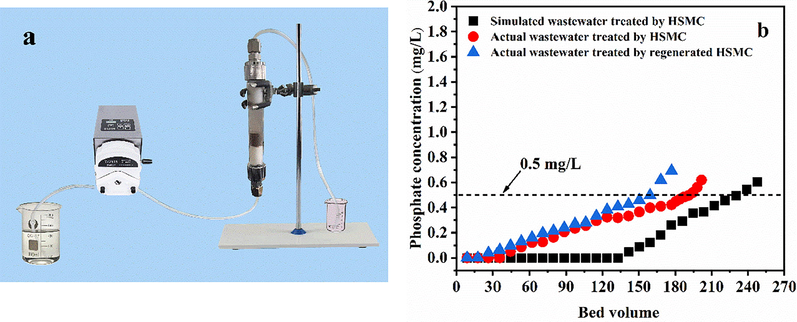
(a) Actual equipment operating diagram of column adsorption tests; (b) Column breakthrough curve of simulated wastewater, actual wastewater and second repeat adsorption of actual wastewater. Adsorption conditions: influent concentration, 2 mg/L; flow rate, 1 mL/ min; temperature, 28 ℃.
The regenerated HSMC after phosphate desorption can continuously treat wastewater at over 159 BV. The amount of actual wastewater treated by the regenerated HSMC was slightly lower than that of the actual wastewater treated by the initial HSMC sample. This can be explained from two aspects. First, the combination of HSMC and phosphate is relatively strong; therefore, it is difficult to completely desorb the phosphate by washing with 1 M NaOH. Second, a small amount of Ca is lost from the HSMC sample by dissolution during washing. These factors lead to a reduction in the number of available binding sites for phosphate removal in the regenerated HSMC sample, resulting in a decrease in its ability to remove phosphate from wastewater. In conclusion, HSMC can treat actual phosphate-containing wastewaters under continuous flow conditions and can be regenerated and reused.
3.3 Adsorption mechanism
3.3.1 pHPZC
To analyze the surface charge of HSMC, the pHPZC value was measured. As illustrated in Fig. 8, the pHPZC of HSMC is 7.5, which is much higher than that of CGCS, indicating that the surface of HSMC is positively charged over a wider pH range. This is favorable for the removal of negatively charged phosphates. After phosphate adsorption, the pHPZC of HSMC decreased, indicating that adsorption occurs by specific adsorption and the formation of inner-sphere complexes. In general, the formation of outer-sphere complexes does not change the isoelectric point of the adsorbent, which is mainly attributed to the insufficient interaction between the adsorbent and adsorbate (Huo et al., 2021). Conversely, inner-sphere complexation (specific adsorption) of the anions makes the adsorbent surface more negatively charged, resulting in a shift in the pHPZC of the adsorbent toward a lower isoelectric point (He et al., 2017).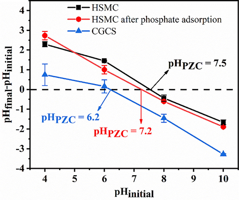
The pHPZC of CGCS, HSMC and HSMC after phosphate adsorption.
3.3.2 Xrd
The XRD patterns of the CGCS and HSMC samples are shown in Fig. 9. The crystal phase in the CGCS sample was mainly quartz. After acid leaching and calcining, hematite appeared in the HSMC sample, indicating that the Fe in the CGCS was activated by the acid. After calcination, the CGCS became a composite (HSMC) with hematite and quartz as the main crystal phases. This may be attributed to the reaction of Fe in the silicate phase with HCl to form ferric chloride or hydrated ferric chloride, which form hematite during high-temperature roasting. After phosphate adsorption, the peak intensity of hematite in HSMC was significantly weakened, indicating that the phosphate ions reacted with hematite. In addition, new Al phosphates were found, indicating that the Al in the HSMC underwent a precipitation reaction with the phosphate ions.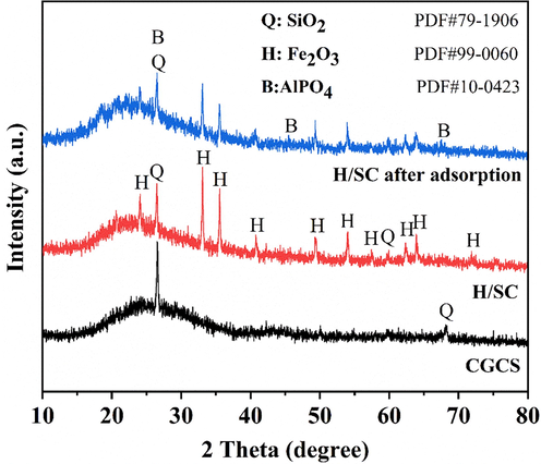
XRD patterns of CGCS, HSMC and HSMC after sorption.
3.3.3 Ftir
The FTIR spectra of the samples are shown in Fig. 10. The weak peaks at 2924 and 2864 cm−1 are the main characteristic peaks of aliphatic structures (—CH/CH2), indicating that some organic carbon structures remain in CGCS (Du et al., 2018; Guo et al., 2020). The bands at 1055 cm −1 corresponds to the asymmetric stretching vibration of Si—O—Al (Du et al., 2018). After acid leaching and water washing of CGCS, this peak shifted to 1080 cm −1 (Si—O—Si), and a new peak appeared at 952 cm−1 (Si—OH) (Zhu et al., 2020), which indicates that the HCl reacts with the Al in the silicon–alumina oxide to break the Si—O—Al bond and form O—Si—O and Si—OH bonds instead. The absorption peaks at 436–481 cm−1 and the band near 778 cm−1 are mainly derived from Si—O and Al—O (Varas et al., 2005; Wu et al., 2021). Comparing Fig. 8a and b shows that acid leaching has a significant impact on the Si—O bond of CGCS. For example, the intensities of the characteristic peaks near 481 and 778 cm−1 increased significantly, indicating that a large amount of metal ions were leached from the CGCS after acid leaching, and a large number of pores were generated on the surface of the CGCS, exposing the interior of the particles. This change was also confirmed by XRF and SEM analyses. These changes in the Si–O functional groups and the results of XRF analysis indirectly indicated that metal elements, such as Ca, Al, and Fe, in CGCS mainly exist in the form of silicates.
FTIR spectra of a: CGCS, b: CGCS after acid impregnation and water washing, c: HSMC, and d: HSMC after phosphate adsorption.
The absorption peak at approximately 3423 cm−1 is related to –OH stretching vibrations, while the bands at approximately 1620 and 1637 cm−1 are ascribed to the bending vibrations of water molecules (Du et al., 2018). Comparing Fig. 8a–c shows that the intensity of the –OH peak of HSMC near 3423 cm−1 is significantly enhanced, indicating that acid leaching and calcination of CGCS significantly increase the hydroxyl content in HSMC, which is favorable for phosphate removal. This may be due to the activation of Ca, Al, and Fe in CGCS by HCl to form hydrated chlorides and (hydr)oxides during high-temperature calcination. The absorption peak at approximately 565 cm−1 probably corresponds to hematite (Cheng et al., 2021; Du et al., 2018), which is consistent with the XRD analysis.
In summary, the HSMC formation mechanism consists of two stages. First, in the HCl impregnation stage, HCl mainly reacts with Ca, Al, and Fe silicates in CGCS to generate metal chlorides or hydrated chlorides. This destroys the original Si—O structure of CGCS and makes it amorphous. Second, in the calcination stage, these metal chlorides or hydrated chlorides form hydroxides or oxides at high temperatures.
The absorption peak near 1080 cm−1 may be related to the stretching vibrations of P—O and Si—O bonds (Cheng et al., 2021; Liu et al., 2019). Notably, the intensity of the peak near 1080 cm−1 increased after phosphate adsorption by HSMC (Fig. 8c and d), indicating the presence of phosphates in addition to Si—O. Meanwhile, the peak at 3423 cm−1 shifted and decreased significantly in intensity after phosphate adsorption, demonstrating that the hydroxyl groups on the HSMC surface undergo ligand exchange with phosphate ions.
To further explore the reaction mechanism between HSMC and phosphate ions, two samples before and after the reaction were assembled into an infrared dataset for two-dimensional correlation spectroscopic analysis. Two-dimensional correlation analysis of different datasets provides synchronized spectra, showing the homology of the spectral signals (Chen et al., 2014). As shown in Fig. S2, four obvious automatic peaks were observed during the reaction between HSMC and phosphate. These peaks were located at 565, 931, 1128, and 3423 cm−1, which correspond to the characteristic absorption peaks of hematite, Al—O, phosphate, and hydroxyl groups, respectively (Saddeek et al., 2014; Varas et al., 2005). The cross peaks at 565 cm−1 (hematite) and 1128 cm−1 (phosphate) changed in opposite directions, whereas the change direction of the peak at 931 cm−1 was the same as that at 565 cm−1 (hematite), indicating that the hematite sites and Al–O bonds of HSMC may be the phosphate binding sites. The intensity of the characteristic peak of the hydroxyl group at 3423 cm−1 decreased significantly, indicating that the phosphate groups undergo obvious ligand exchange with the hydroxyl groups of HSMC.
3.3.4 Xps
XPS analysis was performed to further verify the reaction between Ca, Al, and Fe in HSMC with phosphate ions. As illustrated in Fig. 11, the Fe 2p3/2 peak at a binding energy of 711.3 eV corresponds to Fe2O3, which is consistent with the XRD results. After phosphate adsorption, the binding energy of the Fe 2p3/2 peak shifted by 0.8 to 712.1 eV. The Al 2p peak at 74.3 eV and Ca 2p3/2 peak at 347.9 eV correspond to Al2O3 and calcium hydroxide, respectively. The Al 2p and Ca 2p3/2 peaks shifted to higher binding energies (74.6 and 348.2 eV, respectively). Similarly, the Fe, Ca, and Al peaks shifted to higher binding energies, further confirming that Fe, Ca, and Al in HSMC react with phosphate ions and form inner-sphere complexes (Min et al., 2019). The P 2p peak in HSMC was not obvious but appeared after phosphate adsorption, indicating that phosphate groups were trapped by HSMC. The P 2p binding energy of KH2PO4 was 133.7 eV; however, the binding energy of P 2p in this study was 134.2 eV (Fig. 9d). This indicates that the interaction between the phosphate ions and HSMC does not involve a simple non-specific adsorption but inner-sphere complexation (specific adsorption) via ligand exchange.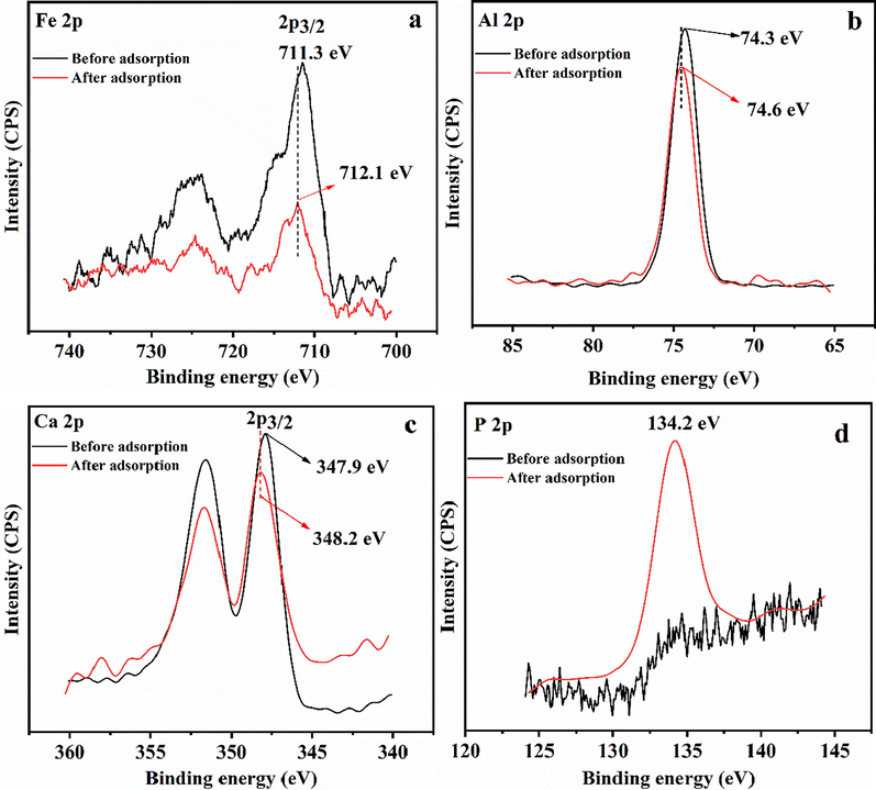
XPS spectra of (a) Fe, (b) Al, (c) Ca and (d) P.
In summary, by analyzing the effect of pH on phosphate removal performance and metal leaching behavior, combined with pHPZC, XRD, FTIR, and XPS analyses, as depicted in Fig. 12, the phosphate removal mechanism of HSMC mainly involves ligand exchange induced by the large number of hydroxyl groups, inner-sphere complexation induced by the presence of major metal (hydr)oxides, the precipitation of calcium and aluminum with phosphate groups, and some electrostatic adsorption induced by the positively charged surface. The contribution of precipitation to the phosphate removal ability was approximately 27 %.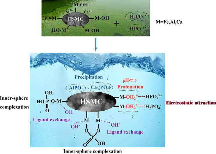
Mechanism of phosphate adsorption on HSMC.
4 Conclusions
CGCS contains large amounts of Ca, Al, and Fe, which have a positive effect on the phosphate removal ability. To fully utilize these metal elements, a novel low-cost HSMC was prepared in situ from CGCS via acid modification. The HSMC formation mechanism consists of two stages. First, HCl mainly reacts with Ca, Al, and Fe silicates in CGCS to generate the metal chlorides or hydrated chlorides. After which, these metal chlorides or hydrated chlorides form hydroxides or oxides at high temperatures. The adsorption behavior is described well by the Langmuir isotherm and pseudo-second-order models, the surface of the HSMC particles is homogeneous and adsorbs phosphates by monolayer adsorption and chemisorption. HSMC is safe and does not cause secondary pollution, and has good adsorption selectivity for phosphate. HSMC can be reused at least four times and can treat more than 191 BV of actual phosphate wastewater. The regenerated HSMC can still treat more than 159 BV of actual phosphate wastewater. The phosphate removal mechanism primarily involves ligand exchange, inner-sphere complexation, and electrostatic adsorption. Traditional methods of preparing porous materials from CGS remove the metal oxides as waste; by contrast, this study utilized them as resources, providing a new way to recycle CGCS.
Acknowledgements
This work was supported by Natural Science Foundation of Ningxia Province (2020AAC03448); Key Research and Development Program of Ningxia Province (2021BEE02019); Special fund for the training project of youth top talent in Ningxia Hui Autonomous Region.
References
- Synthesis of zirconium-modified merlinoite from fly ash for enhanced removal of phosphate in aqueous medium: experimental studies supported by monte Carlo/SA simulations. Chem. Eng. J.. 2021;404:126600
- [CrossRef] [Google Scholar]
- Biocomposite efficiency for Cr(Ⅵ) adsorption: kinetic, equilibrium and thermodynamics studies. J. Environ. Chem. Eng.. 2017;5:400-411.
- [CrossRef] [Google Scholar]
- Adsorption of phosphate onto lanthanum-doped coal fly ash—blast furnace cement composite. J. Hazard. Mater.. 2021;406:124780
- [CrossRef] [Google Scholar]
- Two-dimensional correlation spectroscopic analysis on the interaction between humic acids and TiO2 nanoparticles. Environ. Sci. Technol.. 2014;48:11119-11126.
- [CrossRef] [Google Scholar]
- Metal oxide loaded biochars derived from Chinese bai jiu distillers' grains used for the adsorption and controlled release of phosphate. Ind. Crop. Prod.. 2021;173:114080
- [CrossRef] [Google Scholar]
- Reaction characteristics and evolution of constituents and structure of a gasification slag during acid treatment. Fuel. 2018;224:178-185.
- [CrossRef] [Google Scholar]
- Evaluation of carbon forms and elements composition in coal gasification solid residues and their potential utilization from a view of coal geology. Waste Manage.. 2020;114:287-298.
- [CrossRef] [Google Scholar]
- Preferable adsorption of phosphate using lanthanum-incorporated porous zeolite: characteristics and mechanism. Appl. Surf. Sci.. 2017;426:995-1004.
- [CrossRef] [Google Scholar]
- Optimization of preparation technology for modified coal fly ash and its adsorption properties for Cd2+. J. Hazard. Mater.. 2020;392:122461
- [CrossRef] [Google Scholar]
- Zirconium-modified natural clays for phosphate removal: effect of clay minerals. Environ. Res.. 2021;194:110685
- [CrossRef] [Google Scholar]
- A facile one-pot hydrothermal synthesis of hydroxyapatite/biochar nanocomposites: adsorption behavior and mechanisms for the removal of copper(Ⅱ) from aqueous media. Chem. Eng. J.. 2019;369:529-541.
- [CrossRef] [Google Scholar]
- Hydrothermally synthesized lanthanum carbonate nanorod for adsorption of phosphorus: material synthesis and optimization, and demonstration of excellent performance. Chem. Eng. J.. 2020;380:122153
- [CrossRef] [Google Scholar]
- Adsorption of anionic azo-dyes from aqueous solutions onto graphene oxide: equilibrium, kinetic and thermodynamic studies. J. Colloid Interface Sci.. 2017;496:188-200.
- [CrossRef] [Google Scholar]
- Phosphate adsorption on metal oxides and metal hydroxides: a comparative review. Environ. Rev.. 2016;24:319-332.
- [CrossRef] [Google Scholar]
- Facile one-pot preparation of nitrogen-doped ultra-light graphene oxide aerogel and its prominent adsorption performance of Cr(Ⅵ) Chem. Eng. J.. 2018;338:62-71.
- [CrossRef] [Google Scholar]
- La(OH)3-modified magnetic pineapple biochar as novel adsorbents for efficient phosphate removal. Bioresour. Technol.. 2018;263:207-213.
- [CrossRef] [Google Scholar]
- A new method to prepare mesoporous silica from coal gasification fine slag and its application in methylene blue adsorption. J. Clean Prod.. 2019;212:1062-1071.
- [CrossRef] [Google Scholar]
- Ultra-high capacity of lanthanum-doped uio-66 for phosphate capture: unusual doping of lanthanum by the reduction of coordination number. Chem. Eng. J.. 2019;358:321-330.
- [CrossRef] [Google Scholar]
- Research progress on comprehensive utilization of coal gasification slag. Clean Coal Technol.. 2020;26:184-193.
- [Google Scholar]
- Ftir and physical features of Al2O3–La2O3–P2O5–PbO glasses. J. Non-Cryst. Solids. 2014;387:30-35.
- [CrossRef] [Google Scholar]
- Synergistic dye adsorption by biochar from co-pyrolysis of spent mushroom substrate and saccharina japonica. Bioresour. Technol.. 2017;244:1142-1149.
- [CrossRef] [Google Scholar]
- Enhanced phosphate removal by zeolite loaded with Mg–Al–La ternary (hydr)oxides from aqueous solutions: Performance and mechanism. Chem. Eng. J.. 2019;357:33-44.
- [CrossRef] [Google Scholar]
- Physisorption of gases, with special reference to the evaluation of surface area and pore size distribution. Pure Appl. Chem.. 2015;87:1051-1069.
- [CrossRef] [Google Scholar]
- Natural cement as the precursor of portland cement: methodology for its identification. Cem. Concr. Res.. 2005;35:2055-2065.
- [CrossRef] [Google Scholar]
- Graded synthesis of highly ordered mcm-41 and carbon/zeolite composite from coal gasification fine residue for crystal violet removal. J. Clean Prod.. 2020;277:123186
- [CrossRef] [Google Scholar]
- Removal of hazardous crystal violet dye by low-cost p-type zeolite/carbon composite obtained from in situ conversion of coal gasification fine slag. Microporous Mesoporous Mat.. 2021;312:110742
- [CrossRef] [Google Scholar]
- Adsorption of fluoride by Fe–Mg–La triple-metal composite: adsorbent preparation, illustration of performance and study of mechanisms. Chem. Eng. J.. 2015;262:839-846.
- [CrossRef] [Google Scholar]
- Preparation and application of porous materials from coal gasification slag for wastewater treatment: a review. Chemosphere. 2022;287:132227
- [CrossRef] [Google Scholar]
- Preparation of a new high-efficiency resin deodorant from coal gasification fine slag and its application in the removal of volatile organic compounds in polypropylene composites. J. Hazard. Mater.. 2020;384:121347
- [CrossRef] [Google Scholar]
- Kinetic analysis on the mesoporous formation of coal gasification slag by acid leaching and its thermal stability. Solid State Sci.. 2020;100:106084
- [CrossRef] [Google Scholar]
- Preparation of mesoporous coal-gasification fine slag adsorbent via amine modification and applications in CO2 capture. Appl. Surf. Sci.. 2021;537:147938
- [CrossRef] [Google Scholar]
- Novel hollow microspheres of hierarchical zinc–aluminum layered double hydroxides and their enhanced adsorption capacity for phosphate in water. J. Hazard. Mater.. 2011;192:1114-1121.
- [CrossRef] [Google Scholar]
- Carbon-silica mesoporous composite in situ prepared from coal gasification fine slag by acid leaching method and its application in nitrate removing. Sci. Total Environ.. 2020;707:136102
- [CrossRef] [Google Scholar]
- Temperature-dependent magnesium citrate modified formation of MgO nanoparticles biochar composites with efficient phosphate removal. Chemosphere. 2021;274:129904
- [CrossRef] [Google Scholar]
Appendix A
Supplementary material
Supplementary data to this article can be found online at https://doi.org/10.1016/j.arabjc.2022.104512.
Appendix A
Supplementary material
The following are the Supplementary data to this article:Supplementary data 1
Supplementary data 1


