

Translate this page into:
Top of the line corrosion: causes, mechanisms, and mitigation using corrosion inhibitors
⁎Corresponding authors. ahmobaraki@uj.edu.sa (Aisha H. Al-Moubaraki), Obot@kfupm.edu.sa (I.B. Obot)
-
Received: ,
Accepted: ,
This article was originally published by Elsevier and was migrated to Scientific Scholar after the change of Publisher.
Abstract
Top of the line corrosion (TLC) is a phenomenon of global importance in the crude oil and gas extraction industry and is particularly a source of problems for both offshore and onshore fields. It is often responsible for accelerated corrosion rates, loss of mechanical integrity and catastrophic failures in wet gas pipelines. This form of corrosion cost the oil and gas industry millions of dollars in maintenance and replacement works. The use of corrosion inhibitors is one of the most efficient methods of TLC mitigation and is still an active research area in both the academic and industrial sectors. However, the literature report of TLC mitigation using corrosion inhibitors is relatively scarce. There is limited literature on mitigation of TLC using corrosion inhibitors. A comprehensive and up-to-date review of TLC inhibitors is timely. In the present work, we reviewed scientific research publications related to causes, mechanisms, and mitigation using corrosion inhibitors reported for TLC from 1990 to 2020. Nitrogen-based compounds are the most widely used inhibitor chemistries. Existing critical knowledge gaps have been identified, and future research directions have also been highlighted.
Keywords
Top of the Line Corrosion (TLC)
TLC mechanisms
Multiphase
Stratified flow
Corrosion inhibitors

1 Introduction
Corrosion is a chemical and/or electrochemical reaction between any given material, usually a metal, and its surrounding environment which eventually leads to degradation of the material and its properties (Jones, 1992). Corrosion is considered to be the main cause of failure in the oil and gas production process, particularly in the transport system. Over the last decades, these corrosion failures have led to concerns about energy security, reduced production rates, financial losses and environmental contamination (Jones, 1992; Koch et al., 2002). Due to the development of fields in deeper offshore wells with higher pressure, temperature, and higher levels of hydrogen sulfide, carbon dioxide, and chloride, corrosion costs are increasing.
For example, transmission pipelines in Saudi Arabia cover 111 + km of processing pipelines, and more than 502 km of collecting pipelines which transmit crude oil from wells to the plants (Rehman and Al-Hadhrami, 2014). According to Ruschau and Al-Anezi (2003), 0.20–0.40 US dollars are spent on the prevention of corrosion for each barrel of crude oil, due to the fact that 30% of the failures in the exploration and production processes are caused by internal corrosion.
The 2009 report of the Canadian Association of Petroleum Producers indicated that internal corrosion is responsible for the major pipeline failures (CAPP, 2009). The report of the Alberta Energy Regulator presented in Fig. 1 illustrates that internal corrosion has been a major issue (Alberta Energy Regulator, 2013). Another report confirmed that internal corrosion caused around 15% of onshore and up to 50% of offshore pipeline failures, which is of great concern to the oil and gas industry (Singh and Krishnathasan, 2009). As stated in the studies of Nešić (2007), Nešić and Lee (2003), Singer et al. (2004), Zhang et al. (2007), the most important issues that influence internal corrosion in pipelines are:
-
The water chemistry;
-
The formation of protective scales at the metal surface slowing down the corrosion process;
-
The pH level, because when the pH level is low, the environment in the internal pipeline is more corrosive, and vice versa;
-
The corrosive gases (CO2 and H2S);
-
The increase in CO2 partial pressure typically leads to an increase in corrosion;
-
The effect of acetic acid (HAc) since acid causes a decrease in the pH level;
-
The temperature;
-
The flow (velocity) increase can damage the protective scales formed;
-
The presence of sulfate-reducing bacteria (SRB).
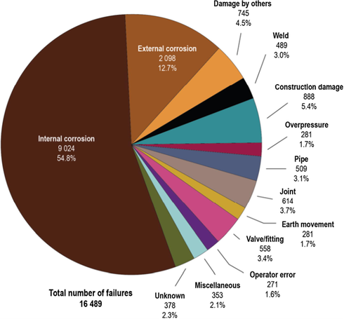
- Pipeline incidents and their causes for all years combined; January 1, 1990 to December 31, 2012 (hits, leaks, and ruptures, excludes pressure tests).
These factors have a great impact on the rate of corrosion because they affect the properties/integrity of the corrosion products formed on the surface of the metal.
Top of the Line Corrosion (TLC) is an internal chemical process that takes place at the upper side of the inner wall of the pipelines because of the condensation of water vapor containing corrosive gases like CO2, H2S, and organic acids – mostly acetic acid (HAc) - as a result of the exchanged heat between the pipe wall and the colder ambient medium. The pipelines affected by TLC usually exist in the stratified and wavy-stratified flow regime (Estavoyer, 1981; Gunaltun et al., 1999; Islam, 2017; Oddo and Tomson, 1982; Piccardino et al., 2004). Due to the complexity of the corrosion process, TLC gains more attention than the bottom of the line corrosion (BLC). Severe problems of localized corrosion are found in TLC because of its critical location (Sadek, 2013). Based on the corrosive constituents, TLC is divided into ‘sweet’ and ‘sour’. The former refers to the environments of high CO2 concentrations, whereas the latter is found in environments containing high levels of H2S (Singer et al., 2011).
Several pipeline failures have been traced to TLC in the last decades. For example, the case of the Lacq sour gas field in France was identified by Estavoyer in 1960 (Estavoyer, 1981). He recognized that TLC existed only at stratified and stratified wavy flow regimes. He then suggested that the main cause was the use of corrosion inhibitor that could not reach the top of the line. Since then, a number of in vitro and in vivo studies have been conducted to detect the TLC mechanism experimentally and theoretically and to develop methods to mitigate it in pipelines.
The “protective film” formed by corrosion inhibitors hinders the interaction between the water that bears the corrosive particles and the pipe wall, which considerably alleviates the corrosion process. Unfortunately, traditional non-volatile liquid inhibitors stay at the bottom of the line and do not reach the condensed water at the top of the line, making them useless for TLC prevention. Consequently, TLC is considered to be one of the most challenging corrosion issues facing the oil and gas industry (Zhang, 2008). That is why a comprehensive understanding of the TLC is important in order to develop more efficient mitigation strategies to combat it.
A previous review by Frenier and Wint (2014) presented the mechanisms of initiation and the prevention of TLC. Based on review, the authors described the complex TLC mechanism and approaches for its mitigation. Another recent review by Askari et al., (2019) focused on the corrosion risks resulting from internal aqueous media in contact with pipe wall in either sweet or sour service. In addition, various types of internal corrosion were discussed in this review, including metal loss, cracking mechanism, and TLC.
Based on the Web of Science (WoS) Database, the research trend in TLC from 1990 to 2020 is presented in Fig. 2. The keywords used for the literature search were “top of line corrosion”, “causes”, “mechanisms”, and “inhibitors”. From the figure, there are about 686 documents related to TLC in the WoS Database from 1990 to 2020. More attention to the study of the TLC phenomenon is observed in the current decade (Fig. 2a), that is, TLC has gained increased attention. However, only about 43 documents on the topic TLC inhibitors can be found in the WoS Database from 1990 to 2020 (Fig. 2b). This make TLC inhibitor a very active area of research which needs more attention.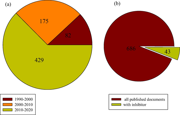
The number of published documents on TLC from 1990 to 2020 based on Web of Science search engine (a) Per decade (b) All published documents compared with only the one containing corrosion inhibitor.
Accordingly, this current review discusses the fundamentals of TLC, its causes, mechanisms, and the role of inhibitors in the mitigation process. Existing research gaps are outlined; challenges and future research directions are also highlighted.
2 Fundamentals of TLC
2.1 Causes of TLC
The role of pipelines is very important in the production process of the oil and gas industry, especially in the transport of liquids and gases from overseas sites to processing plants on land. Pipelines generally operate in stratified flow, transporting wet gas and liquids coming directly from the reservoir containing hydrocarbons, solid particles, carbon dioxide, water, and organic acids, etc., which form a complex mixture (Villarreal et al., 2006). The existence of water dissolved salts, organic acids, solids, and carbon dioxide causes serious corrosion in the pipelines (Gunaltun et al., 1999; Sun et al., 2001). TLC occurs at the upper side of the pipe (between 10 and 2 o’clock positions) due to the great temperature difference between the pipelines and the surrounding areas. The temperature gradient results in water condensation of the unprocessed vapor on the pipe wall, forming droplets of liquid and/or a thin film. Water vapor in the gas phase is condensed in the pipe wall in two different forms (Zhang, 2008):
-
On the side walls, the condensed liquid is formed and due to gravity, and it goes to the bottom of the line.
-
At the top of the pipe, droplets of liquid are formed and remain attached to the metal surface for a long period of time.
The dissolution of corrosive gases, such as hydrogen sulfide (H2S), carbon dioxide (CO2), and the acidic vapors like acetic acid (HAc) lead to severe corrosion problem. The following three phenomena takes place in TLC: condensation, chemical reactions in droplets, and finally corrosion (Zhang, 2008). Hinkson et al. (2008) conducted a study of the corrosivity of TLC and based on thermodynamic experiments, they modelled the water chemistry in TLC droplets. They evaluated the behavior of HAc in gas/liquid equilibrium and concluded that the free HAc concentration in the liquid phase at the top and bottom of the line depends on the pH level.
Fig. 3a shows the scheme of the cross-sectional wet gas pipeline showing TLC conditions, while Fig. 3b represents an example of a TLC attack. Field experience shows that pipelines are often buried in the soil/seabed which can provide thermal insulation while the upper part of the pipe is either not buried or not properly insulated, which leads to water condensation at the upper wall of the pipeline where the temperature difference between the cold environment (outside pipe) and the warm liquid (inside the pipe) is highest (Pojtanabuntoeng, 2012). Gunaltun et al. (1999) described a case of TLC in a wet-gas flowline of the Tunu field that crosses the Mahakam River at different locations in Thailand. Although the corrosion-monitoring systems have shown insignificant internal corrosion rates after 6 years of service, inspection by intelligent pigging found serious inner TLC at two flow lines. Serious corrosion was found at three spots in one line and at two spots in the second line. The lengths of the corroded parts varied from 10 to 100 m. The corrosion occurred at sections where the pipes were interconnecting directly with the river water. These were unburied pipe spots that were subjected to heavy cooling, which in turn led to heavy water condensation. A piece of pipe was removed, and visual examination and laboratory investigation revealed that the top section of the line was covered with FeCO3 (the most common scale takes place in CO2 corrosion:
of several deep pits. This observation emphasized the suggested explanation, that is, TLC was the consequence of water condensation in wet-gas lines in a flow regime of wavy-stratified flow.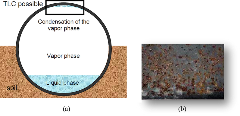
(a) Schematic diagram showing TLC formation on the top of pipeline (b) real image of TLC attack.
The rate of corrosion varies between the bottom of the line and the top of the line. The parameters for determining the rate of corrosion at the top of the line include gas temperature, water condensation rate, CO2 partial pressure, presence of organic acid, and gas velocity (John et al., 2009). In their study, Pots and Hendriksen (2000) showed that, during stratified-flow conditions with multiple phases, the top of a pipeline may be wetted by aggressive condensing water from the vapor phase. They concluded that the following corrosion-causing condition is necessary for TLC to occur in pipelines:
-
Direct contact of the warm inlets of pipelines with the cold seawater;
-
High water-condensation rates and low condensation of glycol;
-
High pipeline-inlet temperatures of approximately over 80 °C;
-
High water–vapor loading;
-
High CO2 partial pressures;
Singer et al. (2013) studied the above-mentioned five parameters and then thoroughly analyzed the effect of each of these five parameters. They investigated the parameters related to uniform corrosion, mesa attack, and pitting. They also provided a comprehensive observation of the phenomena related to TLC in sweet environments. They concluded that droplets could become supersaturated with FeCO3 because of the originally high average corrosion rate. The precipitation of FeCO3 on the metal surface can significantly reduce the average corrosion rate. Nonetheless, the effectiveness of this layer is considerably affected by the droplet renewal rate and the overall corrosivity of the environment; thus, very aggressive localized corrosion can occur. The study concluded that the level of TLC is ultimately the result of complicated interconnections between all these factors. Besides, the study questioned the values used as guidelines for TLC in the industry and made a case for it to be reconsidered. They study concluded that a comprehensive understanding of the mechanisms occurring in TLC has become a necessity to design an efficient TLC inhibition strategy.
A deep understanding of individual factors controlling the corrosion mechanisms of TLC is important in the mitigation strategies for TLC to avoid pipeline failure during service. In the next section, various factors affecting the rate of TLC are presented.
2.1.1 Water condensation rate
The water condensation rate has a pivotal role in determining the corrosion rate. It is affected by several factors including gas temperature, gas velocity, sub-cooling temperature, non-condensable gas concentration, internal pipe diameter, and system pressure (Zhang et al., 2007). Vitse (2002) constructed a flow loop to simulate the field pipelines with TLC issues. Rate of condensation at the top of the line was modified using a double pipe heat exchanger. The impact of CO2 partial pressure, temperature, gas velocity, and rate of condensation was thoroughly studied in distinct experiments. The results “emphasized” the existence of a critical condensation rate and the positive impact of the surface scale at high temperatures. However, the corroded steel at the TLC described in the field literature (Gunaltun et al., 1999; Gunaltun and Larrey, 2000), and visual observation of the condensing model (Zhang et al., 2007) showed that dropwise condensation is more likely to appear, unlike filmwise condensation.
Shant et al. (2017) conducted experiments at three angles, which represent the position of the pipeline, and investigated the flow of the droplet on the inner curvature of the pipe. At each angle, the experiments were conducted using saturated CO2 + 3.5%NaCl at three different temperatures 40, 60, and 80 °C, respectively in order to evaluate pits formation and the general corrosion rate. The results showed that the droplet size on the polished metal surface varies with respect to the temperature, which generates anode or cathode surfaces on the sample. Depending on the droplet morphology formed on the flat surface, pits formation and distribution occurs at a lower temperature. At higher temperatures pits formation interacts with the scales/corroded product and droplet morphology.
In a low condensation regime that forms stagnant droplets, the saturation of FeCO3 is easily accomplished with the droplets if the liquid remains on the metal. The condensation process could cause a change in the corrosivity in the condensed liquid, due to the nucleation and growth of the liquid droplets which will finally drop due to gravity. Eventually, the droplets cause a rise in the pH level and the Fe2+ concentration which favors scale formation. When the condensation develops a constant film on the metal, it is known as “filmwise condensation”. On the other hand, when the condensation develops into drops that do not wet the entire solid surface, it is known as “dropwise condensation”. When such drops reach a certain size, they fall off the surface (Okafor and Nesic, 2007). As a result, during dropwise-condensation, the surface of the metal will be ‘dry’ until another drop begins to form with a lower pH level and more aggressive corrosivity. This frequent sequence changes the nature of the FeCO3 protective layer, which subsequently leads to localized corrosion. Due to the high condensation rate, a localized attack is always obvious at the top of the line. Accordingly, the pitting rate as well as the surface covered by the localized attack both increases. It has been stated that the nature of corrosion on the TLC depends considerably on the size, kind, and staying time of the condensed liquid on the metal (Okafor and Nesic, 2007).
A correlation between water condensation rate and TLC rate has been thoroughly investigated and accepted (Gunaltun and Belghazi, 2001; Méndez et al., 2005; Nyborg and Dugstad, 2007; Ojifinni and Li, 2011). Generally, it is expected that when the condensation rate is low, the corrosion rate is also low, and it increases with increasing condensation. This occurs because the condensed water is quickly renewed at high condensation rates which prevents its full saturation with FeCO3 precipitations. However, a low condensation rate helps the droplets saturated with FeCO3 to form a thin condensed FeCO3 film on the surface in order to decrease the TLC (Singer et al., 2013; Vitse et al., 2003). The reported range of water condensation rates is from 0.001 to 2.25 mL m−2 s−1 (Asher et al., 2012; Dugstad, 2014; Gunaltun and Larrey, 2000; Ojifinni and Li, 2011; Pojtanabuntoeng et al., 2012; Singer et al., 2013; Svenningsen et al., 2013; Svenningsen and Nyborg, 2014). Gunaltun and Larrey (2000) associated TLC with the rate of condensation for the pipeline of the Tunu field and predicted a critical rate of condensation in the sweet system below which this significant range of TLC should not be between 0.15 and 0.25 mL m−2 s−1. Nonetheless, temperature, complexing anions, and the existence of organic acids have an impact on FeCO3 precipitation and can decrease the water condensation rate (John et al., 2009).
Olsen and Dugstad (1991) stated that pipeline suffered high corrosion rates of up to several mm y−1 at very high condensation rates. Consequently, only an insignificant volume of protective corrosion products stayed on the surface, which had no effect on the corrosion rate. A decrease in corrosion rate occurred when the rates of condensation decreased to just above the critical point, because of the growth of corrosion products on the surface. A non-protective scale is formed on the steel surface when a further decline in rates of condensation occurred, just below the critical point. In these scenarios, the rate of condensation does not affect the rate of corrosion. At high operating temperatures and at rates of condensation far below the critical, a protective corrosion film is developed and the rates of corrosion decreased substantially. The effect of water condensation rate on corrosion rate is presented in Fig. 4.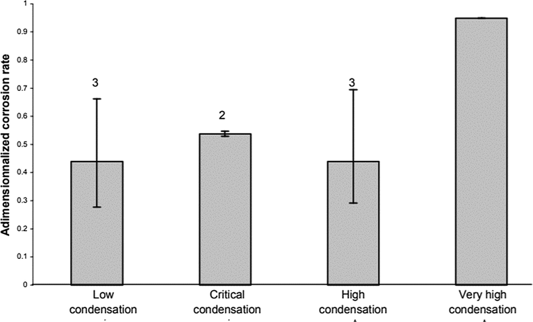
Influence of the condensation rate on the corrosion rate of carbon steel undergoing TLC: Tgas = 70 °C, Gas velocity = 5 m/s, HAc = 171 ppm - Partial pressure of CO2 constant. (Singer et al., 2004).
2.1.2 Gas temperature
Temperature has been recognized as the main factor that affects the TLC rate because of its effect on the rate of condensation and the nature of the corrosion products form, and eventually the rate of corrosion. The temperature of the gas and the outer environment (which results in condensation due to extreme cooling) affects the thickness of the condensate film, the condensation rate, and the film temperature (Chen et al., 2011). Up to date, there are numerous contradictory reports on the influence of low and high gas temperatures on the rate of corrosion due to the successive rate of condensation in the process. At low gas temperature, the condensation rate is expected to be relatively low, and the corrosion rate is adjusted by the electrochemical reaction of the condensed water. However, higher gas temperature results in increased film thickness and higher condensation rate which eventually increases the corrosion rate (Chen et al., 2011).
It is of great interest to note that the corrosion products (scale) produced at higher temperatures could precipitate and deposit on the metal surface, and consequently reduce the overall corrosion process. Olsen and Dugstad (1991) conducted a number of tests to assess the impact of several key factors in a flow loop and an autoclave. Between these factors, temperature was considered the most prominent since it significantly affected the developed film in the process of corrosion, that is, whether it was protective or not. They stated that at substantially low condensation rate and a temperature above 70 °C, the FeCO3 film was very protective. A study of TLC at various condensation rates and various temperatures (25, 40, and 55 °C) was successfully conducted (Anuar et al., 2016). The results showed that an increase in temperature will increase the rate of condensation, which in turn increases the rate of corrosion, that is, the rate of corrosion is higher at 55 °C than at 40 °C. Pitting formation on the steel surface was noticed, which indicated that the corrosion is localized and can cause serious damage to the pipeline in the long term. Scanning Electron Microscopy (SEM) analysis showed that, in both exposed conditions, the FeCO3 layer on the surface is not fully formed (Fig. 5).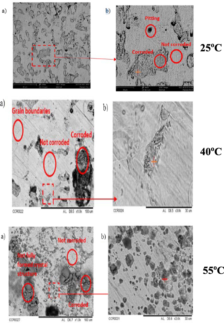
SEM image for X65 steel undergoing TLC at different temperature of 25, 40, and 55 °C at different magnifications: a) 1000×, b) 3000× (Anuar et al., 2016).
Zhang et al. (2007) in a study on TLC, correlated the gas temperature with the nature of corrosion product obtained. They stated that the corrosion product developed at low temperature (40 °C) was mainly porous FeCO3 and less protective due to the increase in the solubility of FeCO3. That is why, at this temperature, the rates of corrosion increased for the first couple of days and then remained constant afterwards. However, at a higher temperature (>70 °C), a dense and protective FeCO3 film was formed. Accordingly, a higher rate of corrosion was found in the initial stage which then decreased with time because of the development of the protective FeCO3 film. The mechanism of the formation of the carbonate film at this temperature could be justified by the saturation of the liquid film and the precipitation of corrosion products, which lowers the pH level locally.
Likewise, Vitse et al. (2003) conducted similar experiments by varying the gas temperature from 40 to 100 °C, respectively. Their report (as shown in Fig. 6) established that the corrosion rate increased with increased temperature and a maximum rate of corrosion was reported at 70 °C. It was suggested that the corrosion rate increases with increase in temperature according to Arrhenius’ law (Equation (1)) (endothermic reaction of corrosion) which is also in line with the report of de Waard and Lotz (1993) on temperature-corrosion rate dependency.
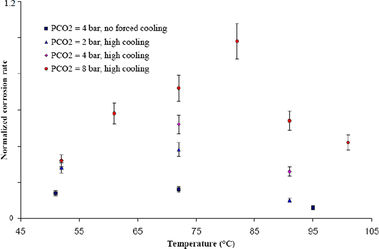
Influence of gas temperature on the corrosion rate of carbon steel undergoing TLC at different pCO2 and different cooling rate; Vgas = 8 m/s. (Vitse et al., 2003).
Thereafter, the trend was reversed, and the rate of corrosion reduced as the temperature increased to 90 °C which suggested a different phenomenon at such temperature.
The study conducted by Vitse (2002) established that the condensation rate was the main parameter affecting TLC at a higher temperature which results in thicker condensed film at the pipe wall. Consequently, the mass transmission of corrosive particles across the condensed liquid to the wall may be restricted. From another point of view, at a higher temperature, the precipitation of FeCO3 on the wall may partially protect the metal from additional corrosion process. A further understanding was obtained from the work of Van Hunnik et al. (1996) on the relationship between precipitation rate and temperature as explained by Arrhenius’ Law. It was concluded that higher gas temperature stimulates precipitation of the FeCO3 scale which dominates the kinetics of the corrosion reaction with a lower rate of corrosion. Another study suggests that a higher temperature regularly results in higher corrosion rates due to a higher level of Fe ions in the condensed water, which raises the pH level of the condensed water. As a result, the change in pH level changes the mechanism of the electrochemical reaction at the pipe wall and favors the formation of protective film, with a corresponding low corrosion rate (Nesic et al., 1996). Accordingly, the variation in gas temperature affect the rates of condensation and the internal wall temperature of the pipe, which in turn, changes the nature and mechanism of the TLC.
2.1.3 CO2 partial pressure
Singer et al. (2013) suggested that there is a connection between the partial pressure of carbon dioxide (pCO2) and the TLC average rates. The study pointed at the relationship between the pCO2 and the nature of the corrosion products. They stated that a lower pCO2 (0.13 bar) is not favorable to the development of protective FeCO3 layers because of the low supersaturation that eventually leads to a low but constant corrosion rate with time. While the initial attack was more aggressive, at high pCO2 (>2 bar), the corrosion average rate decreased with time. This was because the protective FeCO3 layers at higher supersaturation in the condensed liquid was achieved.
Vitse et al. (2002) presented some important understandings of the significance of pCO2 on TLC. They concluded that the pCO2 has little effect on the rate of corrosion at low temperature, high cooling, high temperature and low cooling rate, respectively. Nevertheless, it was observed that the effect of pCO2 is greater at high temperatures and high cooling rates, because it is easier to saturate the liquid film with corrosion products at a low condensation rate, thus raising the pH level and impeding the kinetics of the electrochemical reaction of CO2. Whereas, at high rates of condensation, it is impossible to saturate the liquid film and the pH level could be more susceptible to the effect of the pCO2. Their results agree with the proposal made by Olsen and Dugstad (1991), that both gas velocity and water vapor content play a significant role in the rate of condensation. Son (2004) also concluded that at high pCO2, the corrosion rate is increased by reducing the pH level due to the supply of protons from carbonic acid and increasing the rate of reduction of carbonic acid to bicarbonates. This is shown in Equation (2) as:
Ojifinni and Li (2011) conducted TLC experiments at a fixed rate of condensation (∼0.18 mL m−2 s−1) at 25 and 55 °C wall temperatures and stated that the pCO2 does not have any significant impact on TLC. They observed that when the pCO2 was raised from 50 psi (3.45 bar) to 261 psi (18 bar), a minor increase of TLC rates was detected at both temperatures. The low effect of pCO2 was described by the competitive role of CO2 and corroded Fe2+ which changed the pH level and the supersaturation of the condensed liquid. Similarly, Oehler (2012) reported a slight increase of TLC rates when pCO2 was raised from 5 to 20 bar in the absence of acetic acid, and at fixed rates of condensation.
Vitse et al. (2003) investigated the effect of pCO2 at low and high rates of condensation over a range from 1 to 8 bar and at a bulk temperature of 50, 70, and 90 °C, respectively. It was concluded that at 90 °C without cooling and at 50 °C with cooling, the partial pressure had little effect on the rate of corrosion. However, at 70 and at 90 °C with high cooling rate, there was significant change in the corrosion rate which was influenced by the partial pressure of carbon dioxide as shown in Fig. 7. There is still a little gap between this study and that of the de Waard’s correlation model (de Waard and Lotz, 1993). While Vitse et al. (2003) predicted that for every doubling of the pCO2, the corrosion rate increases by 40% at 70 °C and 110% at 90 °C, de Waard and Lotz (1993) predicted a 60% increase of corrosion rate as the pCO2 doubles.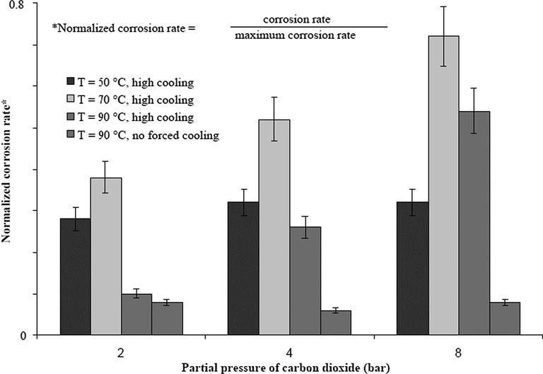
Influence of the pCO2 on the corrosion rate of carbon steel undergoing TLC; Vgas = 8 m/s. (Vitse et al., 2003).
A general conclusion from the two studies above is that at high rates of condensation, the rate of corrosion is significantly affected by the change in pCO2; however, at low rates of condensation, this is not the case. Likewise, at low rates of condensation, it may be easier to saturate (or supersaturate) the condensed liquid with the corrosion products which inhibits the migration of ions from and to the metal surface. This can consequently increase the pH level and slow down the kinetics of the reaction of corrosion by CO2. At increased rates of condensation, the buffering of the pH level of the condensed liquid by Fe ions may be insignificant and the pH level might be more vulnerable to the change in pCO2 (Vitse et al., 2002).
In summary, the pCO2 has negative and positive effects on TLC. It helps in the formation of the FeCO3 film that reduces the rates of corrosion. Also, it lowers the pH level of the condensed liquid and raises the corrosivity of the medium. But its greatest effects depend significantly on other environmental conditions like the water rate of condensation at the top of the line.
2.1.4 Gas velocity
Under dewing conditions, the corrosion rate is not correlated with the gas velocity (Nyborg and Dugstad, 2007). On the other hand, the impact of the gas velocity is affected by the condensation rate. The impact of the gas velocity on the rate of corrosion is calculated by the limitation of mass transfer for the condensation rate in the gas. The corrosion rate increases significantly when the condensation rate reaches a threshold (Gunaltun and Larrey, 2000). This is in accordance with the theory that the saturation level of the corrosive particles in the condensed film governs the corrosion rate. When the condensation rate is high enough, that is, above a threshold that can prevent the liquid film from reaching saturation, the corrosion rate in this case depends mainly on the corrosivity of the liquid.
According to the study conducted by Vitse (2002), it was determined that gas velocity does not directly affect the rate of corrosion but rather affects the rate of condensation which consistently impacts the corrosion rate as illustrated in Fig. 8. It was inferred from the study that both the condensation and the corrosion rates are induced by the gas velocity at 50 and 90 °C, and when the gas velocity descents from 8 to 2 m s−1, the condensation rate decreases. Likewise, it was concluded that the mass transfer is less important at low gas velocity because less water is available for condensation at the pipe wall resulting in low heat loss thereby preventing the phase change for the water phase. At a low condensation rate, there is every tendency to reach saturation on time to form a FeCO3 scale that is not protective unless at high temperature.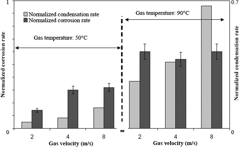
Influence of the gas velocity and condensation rate on the corrosion rate of carbon steel undergoing TLC (high cooling and pCO2 = 8 bar). (Vitse, 2002).
Similarly, the work of Singer et al. (2013) demonstrated that at low velocity, the gas condenses by producing stagnant droplets at the top of the pipe wall. Supersaturated FeCO3 is likely to be very high in the stagnant droplets thereby promoting the development of dense protective layers. When the gas velocity increases, the condensation regime changes from stagnant to sliding droplet at around 10 and 2 o'clock position. However, the droplets flow and slides to the bottom of the pipe. Although the stagnant droplet forms a protective layer, the sliding droplets do not interconnect with the metal surface long enough to produce a protective FeCO3 film. In most cases, the sliding droplets form two different films at the top of the pipe, FeCO3 (protective) films on the major droplet positions and non-protective Fe3C on the favored liquid pathways.
2.1.5 Presence of organic acids
The presence of organic acids in pipelines arises either from natural gas tanks or glycol regeneration that causes serious damage to most wet gas transportation pipelines (Gunaltun and Larrey, 2000). Reports have shown that the average amount of organic acids in produced water in gas and oil systems is in the range from 300 to 2000 ppm, where HAc contributes 50–90% of the organic acid, respectively (Okafor and Nesic, 2007). Formic, acetic, and propionic acids are the main organic acids commonly found in gas and oil wells. The effect of organic acids (HAc) on corrosion in the presence of CO2 has been thoroughly investigated (Garsany et al., 2002; Joosten et al., 2002; Liu et al., 2008; Nafday and Nesic, 2005; Singer et al., 2004). All these studies have reported that the presence of HAc increases the rate of corrosion. The explanation behind this behavior is the ability of HAc to reduce the pH level, thus increasing the solubility of Fe2+ because of the impact of undissociated HAc on the cathodic reaction (hydrogen reduction) of the corrosion process (Okafor and Nesic, 2007). It is important to understand that it is the amount of undissociated HAc that determines the total HAc concentration present in the condensed liquid at the TLC.
In real-life applications, the FeCO3 scale is known to exist on the internal surface of the metal. The impact of HAc on the thickness, growth, and protectiveness of the FeCO3 layer is the subject of contradicting publications. Hedges and McVeigh (1999) found that HAc reduced the thickness and protectiveness of the corrosion layer. However, other reports stated that there is no real effect on the FeCO3 formation and its protectiveness (Nafday and Nesic, 2005). Another study by Fajardo et al. (2007) described the contribution of HAc in relation to corrosion layers. The study claimed that HAc provokes a “scale undermining-effect”, where thicker FeCO3 scales in the presence of organic acids were reported. That study concluded that sufficient FeCO3 was not yet formed because of the higher corrosion rates by HAc; it took longer for the film to hinder further corrosion. Since HAc is volatile, it is condensed on the upper wall of the pipe, thus increasing the corrosivity of the condensed water and this poses a challenge to the integrity of the protective FeCO3 layer. Fig. 9 shows a typical representation of the TLC failure of the underwater pipeline caused by condensation of water in the presence of CO2 and volatile organic acids. The combined effects of water from the external environment and organic acid from the produced fluids increased the condensation rate (Ajayi, 2015).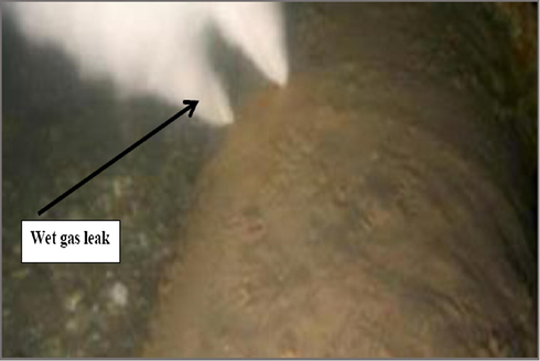
Photo of TLC pipeline failure (under water) caused by the condensation of water vapor on the top of the pipe in presence of CO2 and volatile organic acids (acetic and formic acid). (Ajayi, 2015).
Hinkson et al. (2008) thoroughly investigated the corrosivity and chemistry of the condensate. Using thermodynamics, they aimed at modelling the water found in droplets, specifically assessing the behavior of HAc in the gas/liquid environment. It was found that the free absorption of HAc at the bottom and the top of the line depends on the pH level. Nyborg and Dugstad (2007) demonstrated that the solubility of iron in condensed water increases when HAc is present in the CO2 environment. Due to the increase in the concentration of undissociated HAc in the droplet, the rate of corrosion increases with an increase in the concentration of HAc, thus increasing the concentration of HAc interconnecting with the metal (Okafor and Nesic, 2007).
Because of the increased retention time of the HAc-bearing droplets on the metal, the corrosion rate can also increase (Okafor and Nesic, 2007). According to George and Nešic (2007), it has been proven that the presence of HAc increases the rate of corrosion due to the ‘inversion’ in the ratio of bicarbonate/acetate. This is because at this inversion point, the acetic acid is the dominant source of acidity of the fluid. This reduces the pH level compared to the H2CO3. Gunaltun and Belghazi (2001) also provided some explanations for the increase in the rate of corrosion of carbon steel by HAc in the CO2 environment. They explained that HAc is stronger compared to carbonic acid and reacts quickly with carbon steel compared to ions. The corrosion products are iron acetate, and it is a complex compound soluble in acidified water, and thus increases the rate of corrosion. Iron acetate is known to be soluble, unlike insoluble carbonate. Besides, it is believed that HAc induced a stronger acidic buffering effect on the corrosion products layer than bicarbonate (Crolet et al., 1998).
It is also possible for HAc to interact with bicarbonate, thereby increasing the solubility of FeCO3 and reducing the thickness of the carbonate layer to accelerate the CO2 corrosion process. The increased corrosion rate is due to the formation of thinner FeCO3 layers, which are non-protective because acetate ions can form iron acetate, and transport Fe away from the surface of the metal (Ajayi and Lyon, 2013). The initial results also confirmed that in a CO2 environment, there is a gradual decrease in corrosion rates over time that can be explained by the development of the protective FeCO3 layer. The addition of HAc to the environment led to a substantial increase in the rate of corrosion because of the low pH level in the condensed water as the presence of acetate inhibits the formation of the carbonate layer. When gaseous HAc is present in a multi-phase system, it either adsorbs and helps to enhance dropwise condensation, or it dissolves in water droplets and is dissociated into protons and acetate ions (Okafor and Nesic, 2007). The supply of protons by the free HAc at the metal surface enhances the cathodic reaction and consequently increases the local corrosion rate.
The fundamental role of HAc in CO2 corrosion is still a controversial topic. Amri et al. (2011) reported that the presence of HAc in oilfield brines enhances the occurrence and the rate of localized CO2-TLC. The kinetic behavior of carbon steel in those brines indicates that the impact of the HAc is a balance between a boosted cathodic part reaction rate and an inhibited anodic one, with a subsequent positive shift of the corrosion potential. Both factors contribute to a high risk of localized corrosion in spots where the inhibition effect fails. Non-uniformly adsorbed molecules of HAc cause a substantial difference in the pH level between anodic and cathodic spots. The driving corrosion force between these two spots could be large enough to allow the development of few but deep pits. Okafor and Nesic (2007) stated that the concentration of the undissociated acetic acid greatly contributed to TLC; because the higher the undissociated HAc, the higher the concentration of protons that are available for cathodic reaction during the electrochemical (corrosion) process.
The conclusion reached by Nesic and co-workers is consistent with the results of previous researches that the rate of corrosion correlates with the concentration of HAc (Singer et al., 2004). It was found that at a low pH level, the condensed water is unbuffered and rapidly supersaturated with corrosion products that lead to an increase in the pH level and formation of FeCO3. At low condensation rates, a low concentration of HAc (approx. 18 ppm of undissociated HAc) is sufficient to double the corrosion rate. It will be important to conduct some experiments on the effect of HAc on CO2-TLC to establish more facts about the critical concentration that leads to a significant change in the rate of corrosion.
In summary, organic acids influence the rate of TLC in three ways (Hinkson et al., 2008):
-
Through increasing the cathodic rate of reaction, being a source of protons, HAc can increase the cathodic rate of reaction;
-
Through inhibiting the reaction of the anodic dissolution;
-
Through affecting the protectiveness and solubility of the corrosion films.
In the next section, the nature and the mechanism of TLC in sweet and sour corrosive environment is presented.
2.2 Nature of TLC
In several field inspections, TLC is essentially categorized as localized corrosion (Gunaltun et al., 1999). Pipe failure exists in specific areas, and, in most cases, it does not affect large spots. In the field, when the corrosion appears so large, the corrosion is referred to as “localized uniform corrosion”, rather than “localized corrosion” (Singer, 2017). The first documented case of TLC described it as “sharp-edged pits joined to form large areas of corrosion” (Gunaltun et al., 1999).
In sweet environments (that is, CO2-dominated), the corrosion is referred to as a mesa attack, where the pipe is not uniformly corroded, yet the pits are wide, bare of any layers, flat-bottomed, and surrounded by areas with intact corrosion (Fig. 10) (Gunaltun et al., 2006). Okafor and Nesic (2007) suggested a mechanism for corrosion under liquid droplets containing HAc. Under drop-wise condensation, they correlated the localized corrosion with the existence of protected and non-protected regions. The results inferred the development of galvanic cells between regions covered by a FeCO3 film and film‐free regions.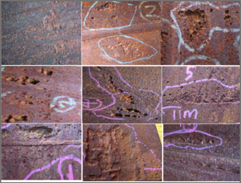
Typical TLC failure in CO2-dominated environments. (Gunaltun et al., 2006).
Singer (2013, 2017) investigated the localized TLC and presented a prediction model. The study stated that TLC rates correlates with the rates of condensation, the gas temperature, and the presence of HAc in the condensed water. Because of the renewal of the condensed water, the local breakdown of the FeCO3 film initiates the localized corrosion. Additionally, the exact location of the droplets is not directly related to the zone of the localized attack.
The first experimental study that investigated the TLC phenomenon was published by Amri et al. (2008, 2010, 2011). They presented a conceptual model of pit dissemination; however, more work was still needed. A new study by Islam et al. (2018a) presented a novel electrochemical probe to measure the rate of TLC of carbon steel. Later, to determine the precision and challenges of this new probe, a number of tests at different water condensation rates were conducted. The study demonstrated a step forward in the development of a probe for the electrochemical study of TLC. Some observations were recorded in this study, and the result indicates the predominance of uniform corrosion, depending on the nature of the conditions that were chosen to conduct the experiments. The localized nature of TLC may appear at other conditions (for example, the presence of organic acids, longer-term study, etc.) that have not been addressed using such a new probe.
In a sour environment (that is, H2S-dominated) the mode of the corrosion attack is speculative, since both uniform and pitting corrosion occurs. The mechanism of uniform H2S corrosion is still in need of further research (Sun and Nesic, 2007). Camacho et al. (2008) reported that in the presence of CO2/H2S of different ratios, the form of corrosion was strictly uniform, and no traces of localized attack could be found. FeS film has always been the principal corrosion present on the carbon steel surface. Singer et al., (2011) continued Camacho’s work (Camacho et al., 2008), and revealed that the existence of HAc in the presence of H2S, appeared to influence the cohesion of the FeS film and prompted localized corrosion.
According to the study conducted by Yaakob et al. (2016), localized corrosion at a partial pressure of H2S below 0.08 mbar was found. The extent of the localized corrosion was more serious at a gas temperature of 40 °C than at 60 °C. The localized corrosion is thought to be dominant because of the development of a non-homogenous corrosion layer and the imbalance between the rates of protective layer formation and the corrosion.
In a recent research involving simulating sour TLC in the existence of methanol, it was shown that for 10 bar H2S + 10 bar CO2, the TLC mass loss rate was 0.2–0.3 mm y−1 of general corrosion (Svenningsen, 2017). The presence of methanol led to serious localized corrosion with a slight increase in the mass loss rate of corrosion. Esmaeely et al., (2017) hypothesized in a recent study that, at low concentrations of H2S, defects in the corrosion layer allowed the corrosive particles to reach the steel surface, which in turn led to localized corrosion.
2.3 Mechanisms of TLC
TLC functions very differently depending on whether the environment is CO2 dominated, referred to as the sweet environment, or H2S dominated, referred to as the sour environment. The composition of the corrosion product layer (either FeCO3 or FexSy) should be a good guide for the corrosion mechanism’s dominance, but this principle can only be used in failure analysis when such information is readily available.
2.3.1 Sweet TLC environment
The existence of CO2 (without H2S) in the system leads to a corrosive environment known as sweet corrosion. General chemical reactions participating in the corrosive mechanism are shown below (Nešić and Sun, 2010; Tan et al., 2010).
Aqueous CO2 is formed when the gas dissolves in water and is then hydrated to form carbonic acid (H2CO3):
The dissociation of H2CO3 into the solution produces Hydrogen ions (
) and bicarbonate (
):
Another
and
are then formed as a result of
dissociation:
In CO2 corrosion for carbon steel, further electrochemical reactions should be considered. The anodic reaction is the oxidative solubility of iron in an aqueous solution:
The cathodic reactions cover the reduction of
, H2CO3,
, and/or H2O:
Therefore, the overall reaction of steel in aqueous CO2 in sweet TLC environment can be written as:
Thermodynamically, the precipitation rate depends on the supersaturation degree and temperature. Similarly, organic acids have been reported to influence the characteristics of the corrosion layer (Crolet et al., 1999; Dugstad, 1992; Nafday and Nesic, 2005). In general, FeCO3 layers protect against CO2 corrosion, if their cohesion is not challenged by mechanical damage, sudden changes in chemistry, or changes in operating conditions.
2.3.2 Sour TLC environment
Sour environments are defined by the presence of a significant amount of H2S typically with CO2 present as well. Corrosion mechanisms of H2S TLC have not been researched like their CO2 counterparts (Smith and Joosten, 2006). It appears that the controlling parameters for both mechanisms are different; however, such differences are mainly because of the characteristics related to each type of corrosion. The presence of H2S in the gas leads to dissolution (Smith, 1993; Sun, 2006):
Aqueous H2S can directly dissociate after dissolving in the solution. Bisulfide (
) and sulfide (
) species can form in the dissociation processes, as shown in the reactions below:
Like the sweet environment, acidic H2S can act as an additional source of hydrogen ions. The possibility of reduction of H2S also exists:
Ultimately, the overall reaction of steel in sour TLC environment can be written as:
Depending on the existing conditions, several types of FeS are formed (troilite, cubic FeS, and mackinawite). Experimental studies illustrated the existence of two different layers: a porous and thick outer layer, and a thin and dense inner layer (Singer, 2011). TLC is directly related to the characteristics of the corrosion layers. Therefore, deciding whether FeS or FeCO3 precipitates are of major importance for TLC predictions (Brown et al., 2003; Pots et al., 2002; Smith, 2011).
Some sour corrosion properties have been suggested (Singer, 2017):
-
Sour TLC does not appear to be as dangerous or as common as sweet TLC;
-
The rate of condensation may not be the chief controlling factor compared to sweet TLC;
-
The impact of the attack depends on the protectiveness and type of the iron sulfide film formed at the condensed water/steel interface;
-
The gas temperature could subsequently be a key factor since it directly influences the phase identity and physical characteristics of the formed iron sulfide.
In the next section, we will discuss the mitigation of TLC using corrosion inhibitors. The different classes of corrosion inhibitors used in the mitigation of TLC such as amine-based inhibitors, imidazoline-based inhibitors, thiol-based inhibitors and monoethylene glycol-based inhibitors will be outlined.
3 Mitigation of TLC using corrosion inhibitors
Effective mitigation of TLC in multiphase natural gas pipelines by using corrosion Inhibitors is still an active area of research, both in the academic and industrial sectors (Shen et al., 2013). Most of the work on TLC is still at the laboratory and screening phase to determine the best corrosion inhibition formulations and the treatment techniques to transport the inhibitors to the upper wall to prevent the electrochemical reaction of condensed water at the metal surface. The effectiveness of corrosion inhibitors used in protecting the TLC depends on its volatility to a great extent. Furthermore, the severe conditions because of the low pH level of freshly condensed water and the elevated pressure and temperature require a strong harmony between the inhibitor and the metal surface (Shen et al., 2013).
Corrosion is a crucial worldwide problem that strongly affects metals. Out of the several ways to prevent corrosion, volatile corrosion inhibitors (VCIs) are predominantly used as a method of temporary protection. Volatile Corrosion Inhibitor (VCI) is an inhibitor that, at normal temperature, has volatile property apart from being solid or liquid. It is a mixture of chemical compounds that slowly vaporizes. These compounds have the ability to vaporize and condense on the surface of the ferrous or non-ferrous material and make the substrate less susceptible to corrosion but work only in a confined space. The gas vapor reacts with the metal surface, condenses, and is then hydrolyzed by any moisture and finally releases ions that hinder metal corrosion. The inhibition of VCI depends significantly on the volatility of these compounds; since durable protection needs low volatility, whereas fast protective action necessitates high volatility (Olajire, 2017).
The development and use of VCIs for field applications are considered to be good potential for corrosion mitigation. VCIs are infused into the liquid phase, like conventional bottom of the line (BLC) inhibitors. Then the VCIs evaporate and co-condense at the TLC. VCIs can reach the entire surface of the carbon steel pipeline, because of their volatility, including complex-shaped parts and cracks (Andreev and Kuznetsov, 1998). Nevertheless, developing the chemical formulation that will retain sufficient inhibitive properties, with superior volatility, has proven to be a serious issue (Gunaltun et al., 2010).
VCIs are not a brand-new concept. In fact, they have already been used in the packaging industry (Gunaltun et al., 2010; Martin, 2009, 1997; Shen et al., 2013). Most current VCIs used in the TLC-researches are amine-based inhibitors, imidazoline-based inhibitors, thiol-based inhibitors, and some other compounds such as mono ethylene glycol (alcohol), azoles, and aldehydes. Their inhibition effectiveness greatly depends on several factors such as, their chemical structure, the operating conditions, the features of the metal surface, and the environments in which they exist (Singer, 2013).
The potential corrosion inhibitors for TLC application should meet the following properties (Shen et al., 2013):
-
Effective in the existence of organic acid;
-
Appreciable saturated vapor pressure;
-
The low potential of reaction with acidic environments.
3.1 Amine-based inhibitors
Amines are chemicals that are analogs of ammonia (NH3), in which either one, two, or three hydrogen atoms of ammonia are replaced by a substituent such as an alkyl or aryl group. Amines are classified as aliphatic, having only alkyl groups attached, or aromatic, having one or more aryl groups attached. Fig. 11 a-d represents the general formula of aliphatic amines. The nitrogen of the amine has two electrons, which are attracted to the polar metal surface. When it is attracted to the metal, the rest of the molecule (alkyl groups) becomes very hydrophobic driving out water and hindering the corrosion drastically. Most aliphatic amines are cheaper, low toxic, and many are harmless, natural components of foods and pharmaceuticals.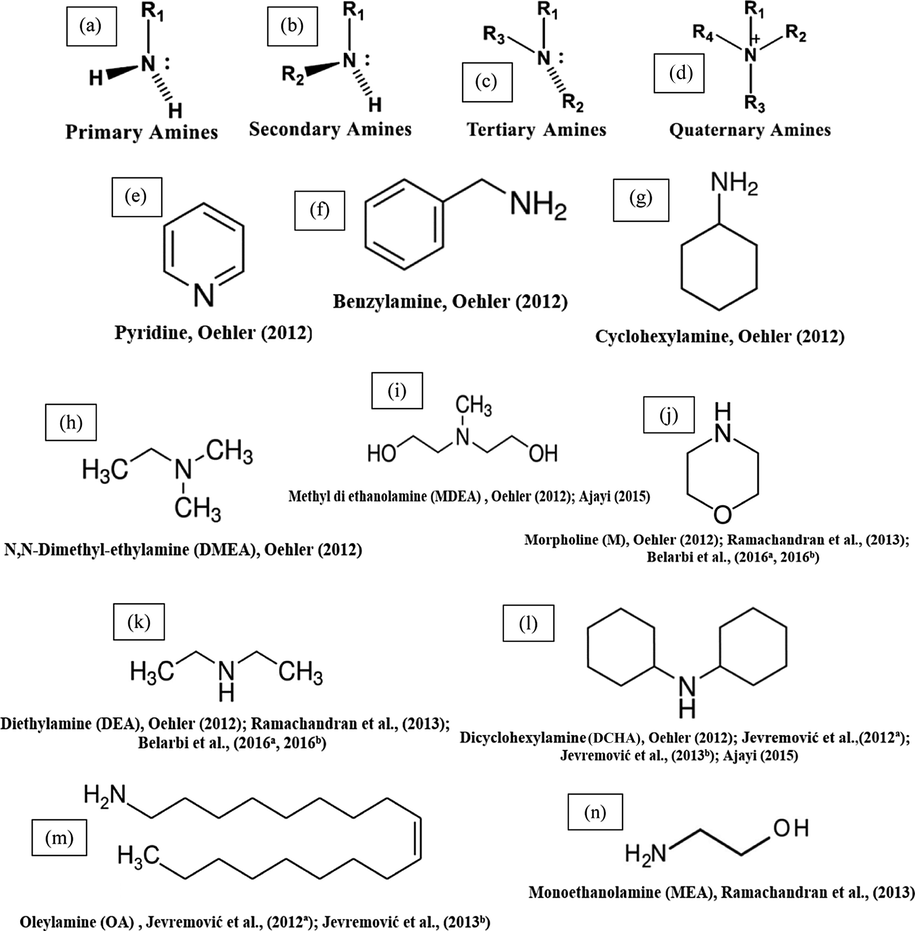
Chemical structures of some TLC inhibitors based on amines.
Different amines are used as operating materials during the production and purification of crude oil and natural gas; for instance, as corrosion inhibitors, and alkanolamines as absorbents in sour gas treatment plants, etc. (Kadnar, 1999). Generally, amine-type compounds appear to be the most reported TLC inhibitors.
A comprehensive research study was successfully implemented by Gunaltun et al. (2010) in order to determine and test the effectiveness of a volatile inhibitor. Based on the laboratory results, a combined product that contained a volatile amine inhibitor and a bottom line inhibitor was developed and tested (PX 4856 R). Its performance was better than the volatile inhibitor alone. The preliminary laboratory tests were confirmed by loop tests. When the volatile inhibitor was infused, the localized corrosion rate as well as the general corrosion rates declined dramatically.
Three generic volatile inhibitor compounds, a primary (VCI 1), a secondary (VCI 2), and a tertiary (VCI 3) amine have been tested for TLC inhibition on carbon steel using different tests (Oehler et al., 2012). The results showed that all three VCIs mitigate TLC. The authors found that despite the substantial differences in concept, the tests used in this study delivered similar results in general. In all the systems, the performance of the VCIs followed the order VCI 3 > VCI 2 > VCI 1. The findings from this work concluded that the efficiency of a single component was limited, but it is possible that a multi-component formulation would be more effective.
Oehler (2012) examined 16 generic amines VCIs for their ability to inhibit TLC. Some of these inhibitors are shown in Fig. 11 e-l. Different tests were applied to examine the inhibition efficiency of these compounds on TLC. In the presence of VCIs inhibitors and according to the results, inhibitors were divided into two groups: “Low performing VCIs” and “High performing VCIs”. The study concluded that for sufficient inhibition of TLC, the molecular weight and the boiling point of the molecules should be low, while the volatility should be high. These necessary characteristics are not often found in a film-forming compound, as they are long-chained polar molecules. Consequently, all successfully tested TLC inhibitors have stronger neutralization ability than film-forming ability.
Jevremović et al. (2012a) investigated the effect of a dicyclohexylamine and oleylamine compound (DCHA + OA) (Fig. 11 l, m) as a corrosion inhibitor for TLC. The volatile features of the inhibitor DCHA + OA were examined. It has poor volatility and did not protect the top of the line. However, when it was carried to the top through its own foam, it decreased the corrosion rate substantially.
Jenkins and Gilbert (2012) summarized the test results for a new corrosion inhibitor (TOL-CI) and their performance in preventing TLC. The inhibitor consisted of traditional gas pipeline corrosion inhibitor blended with standard and novel volatile amine compounds. In all the tests, the product gave >80% corrosion protection and no localized corrosion was observed. Based on early field trial results, the inhibitor was also found to work effectively when applied in a multiphase gas pipeline. Laboratory tests demonstrated that the addition of TOL-CI did not cause any process problems with respect to foam formation in MEG regeneration units.
Jevremović et al. (2013b) applied a novel method involving injecting of corrosion inhibitor within a foam medium, which was successfully applied in the previous research in a multiphase large scale flow loop to simulate field settings (Jevremović et al., 2012a). The study concluded that the TLC rate of carbon steel was successfully reduced by the foam that contains the mixture of DCHA + OA corrosion inhibitor (Fig. 11 l, m). However, the inhibition effect lasted over 20 h.
Ramachandran et al. (2013) reported the results of a laboratory study of the inhibition of TLC by various volatile amines corrosion inhibitors including morpholine (M), diethylamine (DEA), and monoethanolamine (MEA) (Fig. 11 j, k, n), and a proprietary corrosion inhibitor (CI) using a new technique, the Quartz Crystal Microbalance (QCM) under simulated TLC conditions. The QCM results demonstrated that morpholine (M) and the proprietary corrosion inhibitor (CI) significantly affected the water condensation rate and consequently showed good TLC protection, while DEA and MEA had little/no effect on water condensation and TLC corrosion.
Miksic et al., (2013) conducted a study to evaluate a wide variety of candidates to find TLC inhibitors that are effective in acidic environments. Different compounds were tested based on their physical–chemical characteristics, in addition to the available data about the mechanisms of the corrosion prevention, such as, Filming amine, Alkoxylated amine, azoles, certain acetylene alcohol, and others. Different tests illustrated that azoles, “green” volatile aldehydes, and certain acetylene alcohols are the best potential for providing TLC protection. On the other hand, it was also found that the low molecular weight amines and their derivatives did not work as good inhibitors due to their neutralization in acidic media.
The effectiveness of methyl diethanolamine (MDEA) and dicyclohexylamine (DCHA) (Fig. 11 i, l) as TLC inhibitors was studied by Ajayi (2015) using different techniques. The results revealed that the addition of MDEA to the wet gas leads to a significant reduction in the corrosion rate (up to 50 h) which acts as a pH stabilizer, favoring FeCO3 film formation. The results obtained indicated that DCHA had good inhibition characteristics for TLC. There was also a progressive increase in polarization resistance values with time which indicated a reduction in corrosion with time. This study concluded that MDEA and DCHA were very good corrosion inhibitors for carbon steel in brine solution full of CO2 gas at 60 °C for TLC.
Electrochemical techniques were used to study bottom of line (BLC) corrosion in order to further realize the TLC inhibition mechanism in the existence of morpholine (M) and diethylamine (DEA) (Fig. 12 j, k) in a mildly acidic pH level and CO2 environment (Belarbi et al., 2016a, 2016b). The results showed that the increase in the pH level after the addition of DEA and M into the aqueous solution may be responsible for the decline in the TLC rate. Morpholine and diethylamine did not have significant filming properties.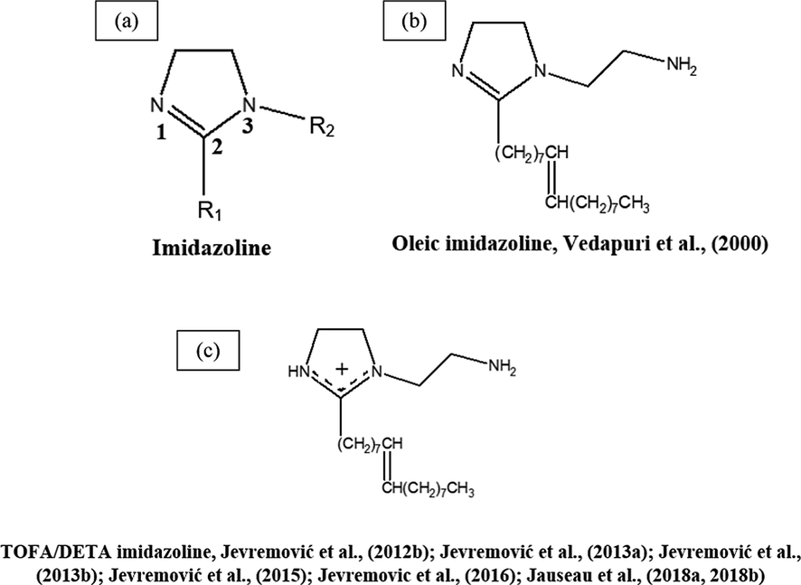
Chemical structures of some TLC inhibitors based on imidazolines.
Thomson et al. (2016) adopted a two-stage methodology to evaluate formulations for both TLC and BLC corrosion inhibition. The method involved an initial screening step using a distillation set-up followed by a longer-duration test in an autoclave system. This work showed that distillation can provide rapid and effective screening of chemicals for preventing TLC. The results of these test indicated that conventional film-forming quaternary amine inhibitors which perform well against BLC may provide little or no protection against TLC.
In a recent study by Jenkins and co-workers carried out to develop test methods suitable for assessing inhibitor performance in controlling TLC (Jenkins et al., 2018), two corrosion inhibitors (TOL-1 and TOL-2) were tested containing different volatile amine components. The study showed that the concentration of the volatile inhibitors and film formers in the condensing water was much lower than the concentration present in the bulk brine phase at the start of the test. Based on the test results, corrosion inhibitors do not mitigate TLC by pH modification of the condensing brine. However, to achieve the low inhibitor concentration in the gas phase and the condensing water required to control TLC, a high initial dose rate of inhibitor is needed (500 ppm).
Table 1 contains amine-based chemistry reported as TLC-inhibitors for steel. The application of amines was mainly restricted to a specific category of steel, as there is no significant work on Cr-type steels and many other very important categories of low carbon steel. It is also noted from the Table 1 that low corrosion rates and high inhibition efficiencies were obtained only in the case of using high concentrations of amines (≥500 ppm). Reducing the concentration to <500 ppm results in poor TLC protection. Although amines were applied in a variety of solutions such as DI water, NaCl, and brine solutions with and without HAc with good results, these solutions are not aggressive enough and most of them contain low concentrations of dissolved solids. However, whether the reported inhibition efficiencies can be repeated in highly aggressive conditions or not is still uncertain. Furthermore, the amines have not been well examined under real hydrodynamic turbulence flow conditions. Test duration: 2 weeks, 4 weeks Condensation rate: 0.25 mL/m2 s HAc concentration: 500 ppm Inhibitor concentration: 500, 2000 ppm Technique: WL, electrochemical study in a corrosion cell, ER probe, large scale flow loop Test duration: 7 days Test solution: 1000 ppm HAc + 0.1% NaCl Inhibitor concentration: 1000 ppm pH: 3.05–3.15 Technique: LPR, WL, autoclave, IC. Test duration: 5, 7 days Test solution: 0.1% NaCl Condensation rate: 0.25–0.40 g/m2/s HAc concentration: 0, 1000 ppm Inhibitor concentration: 1000 ppm Technique: WL, LPR, autoclave, IC, SEM, EDX, IFM Test solution: 3% NaCl HAc concentration: 1000 ppm pH: 4 inhibitor concentration: 1000 ppm Technique: ER measurements Test solution: brine (1%, 1000 ppm NaCl and 500 ppm acetic acid) Condensation rate: 0.25 – 0.5 mL/m2/s pH: <3, 3.1 Inhibitor concentration: 10, 25, 50, 500 ppmv Foam: 100 mL mono-ethylene glycol (MEG) Technique: WL, LPR, autoclave, foaming test Test solution: DI water + 1000 ppmv of HAc pH: 3.5–4 Inhibitor concentration: 5000 ppmv Foaming agent: sodium C14-16 olefin sulfonate Foaming agent concentration: 10 vol% Superficial gas velocity: 1.4 m/s Technique: large scale flow loop Test duration: 14 days Test solution: 50% light hydrocarbon + 50% synthetic brine mixture Inhibitor concentration: 2 ppm Technique: LPR, QCM Test duration: 1, 2, 4, 6, 8, 16, 18 h Test solution: 3.58% synthetic sea salt and 5% diesel fuel in DI water, 50 mL 500 ppm HAc in DI water Gas type: Natural gas Acid gas content: H2S 1.74 mol%, CO2 1.42 mol%, O2 25 ppm pH: 3.5 Inhibitor concentration: 1.2 g, 16.6l/MMcm/day, various Technique: loop test (WL), ER, LPR, visual assessment Test duration: 1–5 days Test solution: 1% NaCl Condensation rate: moderate HAc concentration: 100, 500, 1000 ppm Inhibitor concentration:100, 500, 1000, 2000 ppm Technique: WL, OCP, LPR, EIS, PDP, SEM, XRD, XPS Test solution: 1% NaCl Condensation rate: 0.6 mL/m2/s pH: 4.3, 4.7, 4.8 Inhibitor concentration: 400 ppmv Technique: WL, EIS, LPR, SEM Test solution: reverse osmosis water containing 1000 mg/L KCl HAc concentration: 0, 500 ppmv pH: 3.80, 3.35 Inhibitor concentration: 500 ppmv Technique: LPR, autoclave (WL) Test duration: 90 h Test solution: brine (1000 ppm NaCl + 500 ppm acetic acid) pH: 3.1 Inhibitor concentration: 25, 50, 500 ppm/vol Technique: WL, LPR, LC-MS CR: Corrosion rate; IE%: Inhibition efficiency; FL: Flow Loop; DI: Deionized; WL: Weight Loss; EIS: Electrochemical Imedance Spectoscopy; LPR: Linear Polarization Resistance; IC: Iron Concentration; SEM: Scanning Electron Microscopy; EDX: Energy Dispersive X-Ray; IFM: Infinite Focus Microscope; ER: Electrical Resistance Probe; QCM: Quartz Crystal Microbalance; XRD: X-ray Diffraction; XPS: X-ray Photoelectron Spectroscopy; PDP: Potentiodynamic Polarization; OCP: Open Circuit Potential; LC-MS: Liquid Chromatography–Mass Spectrometry.
Corrosion Inhibitor
Metallurgy
Temperature and Pressure
Experimental Conditions
Maximum protection
Reference
PX 4856 R: containing volatile amine (PX 4803R) + bottom line corrosion inhibitor
X65 Carbon steel
70 °C; 0.7 bar
CR (ER): 0.3 mm/y
IE%: 88.0%
CR(FL): 0.4 mm/y
IE%: 80% after 28 dGunaltun et al. (2010)
primary, secondary, and tertiary amine
UNS G10180 Carbon steel
91 °C; 20 bar
IE% (IC): 58%
Oehler et al. (2012)
Generic volatile amines
1030 Carbon steel
91°, 115 °C; 5, 10, 20 bar
CR(IC): 0.56 mm/y
IE%: 65%Oehler (2012)
Mixture of dicyclohexylamine + oleylamine (DCHA + OA)
X65 Carbon steel
70 °C; 69 kPa
CR (ER): 0.1 mm/y
IE%: 80%Jevremović et al. (2012)
Amine
UNS G10180 Carbon steel
90°, 120 °C; 0.3, 11.25 bar
CR (WL): 0.1769 mmy/mL/m2/s
IE%: 88.6%Jenkins, Gilbert (2012)
Mixture of Dicyclohexylamine + Oleylamine (1:1 vol%) (DCHA + OA)
X65 Carbon steel
60 °C; 1.1 bar
CR: 0.15 mm/y
IE%: 50%Jevremović et al. (2013b)
Morpholine (M), diethylamine (DEA), monoethanolamine (MEA), a proprietary corrosion inhibitor (CI)
Different metals
48.9°, 60 °C; atmospheric, 100 psi
IE%: 81%
Ramachandran et al. (2013)
Filming amine, Alkoxylated amine, and other inhibitors
UNS G10180 (SAE1018) Carbon steel and X65 Carbon steel
70°, 177 °C; 4.14 MPa, 68.95 kPa
CR: 0.027 mm/y
IE%: 98%Miksic et al. (2013)
Methyl di ethanolamine (MDEA), Dicyclohexylamine (DCHA)
60 °C; 0.81 bar
IE% (LPR): 92%
Ajayi (2015)
Diethylamine (DEA), Morpholine (M)
X65 Carbon steel
65 ± 2 °C; 0.66 bar
CR(WL): 0.5 mm/y
IE%: 44%
Belarbi et al. (2016a, 2016b)
Quaternary amine
C1018 Carbon steel
70, 80 °C; 5 bar
CR(WL): 0.02 mm/y
IE%: 78% in 0 ppmv HAcThomson et al. (2016)
Amine
UNS G10180 Carbon steel
90 °C; 0.3 bar
CR (LPR): 0.01 mm/y
IE: >99%Jenkins et al. (2018)
3.2 Imidazoline-based inhibitors
Imidazoline corrosion inhibitors are efficient water-based corrosion inhibitors that can be used in both the neutral medium settings, and in the acid and alkaline settings as well. Imidazoline chemistry is the basis for one of the dominating types of film-forming organic corrosion inhibitors. Imidazolines are heterocyclic compounds with two nitrogen atoms (Zhou et al., 2018). Fig. 12 a, shows the structure of imidazoline composed of three substructures. The long hydrocarbon chain (R1) develops hydrophobic layers in the solution, which prevents the interaction between the corrosive particles and the metal. The pendant side chain with an active functional group (R2) is generally composed of oxygen, nitrogen, and other heteroatoms, that leads to stable adsorption on the surface (Jaal et al., 2014).
Vedapuri et al. (2000) measured the TLC and BLC rates of a pipe in wet gas multiphase flow at pCO2 of 0.46 MPa and 0.79 MPa and temperatures of 40 °C and 60 °C, in a high pressure 10 cm diameter system. The used inhibitor was an oleic imidazoline active compound (Fig. 12 b) dissolved in isopropyl alcohol and water. The results showed that at pCO2 of 0.46 MPa, the addition of 50 ppm inhibitor substantially reduced the corrosion rate. More addition of inhibitor had no further effect on corrosion. At a higher pressure of 0.79 MPa, increasing the inhibitor concentration to 100 ppm further decreased the corrosion rate.
John et al. (2009) used the high-pressure/high-temperature autoclave with an externally cooled sample tube as a novel method for the simulation of TLC conditions. A variety of generic and commercial inhibitor formulations were used in this study and only the results of imidazoline-based inhibitors have been reviewed here. The results revealed that the high solubility of the tall oil imidazoline formulation in the continuously condensing water on the tube surface limits its persistence. Indeed, the autoclave results indicated a complete loss of protectiveness within 24 h. Imidazoline/quaternary ammonium formulation showed to be highly effective in mitigating carbon dioxide corrosion in simulated TLC conditions for up to 450 h, and this was due to the presence of a volatile constituent within the formulation. The inhibitor amide/imidazoline formulation had a relatively high initial corrosion rate which was maintained for the test duration. This may suggest the formation of a persistent inhibitor film.
Jevremović et al. (2013a, 2012b) applied a novel idea to mitigate TLC when using corrosion inhibitors. This novel idea included the injection of the corrosion inhibitor into a foam medium. The performance of the tall oil diethylenetriamine imidazoline (TOFA/DETA imidazoline) within a foam matrix was determined using an innovative experimental glass cell setup (Fig. 12c). The TLC rate of carbon steel was significantly declined by periodic treatment with the foam matrix with TOFA/DETA imidazoline. This study showed that the foam matrix with TOFA/DETA imidazoline can be used to apply batch inhibition of TLC.
After successful laboratory experiments to mitigate TLC (Jevremović et al., 2013a, 2012b), Jevremović et al. (2013b) applied this novel method in a large scale flow loop in order to mimic more realistic TLC conditions. The study concluded that the TLC rate of carbon steel was efficiently diminished by regular treatment by the foam containing a high concentration of a TOFA/DETA imidazoline corrosion inhibitor (Fig. 12c). However, the effect was not persistent, and the inhibition effect lasted between 3 h and 15 h.
Jevremović et al. (2015) later attempted to improve the efficiency of the TOFA/DETA imidazoline (Fig. 12c) for a longer period of time by investigating the inhibitive features of the foam medium with TOFA/DETA imidazoline infused under two conditions: stagnant and flowing using the same experimental procedures in the previous work (Jevremović et al., 2013b). The results revealed that the infusing under flowing conditions led to persistence in corrosion inhibition longer than that of the infusing under stagnant conditions. Successive infusing of foam containing TOFA/DETA imidazoline led to approximately 90% inhibition effectiveness, and the inhibition impact lasted up to 50 h. the results indicated that a slug of foam with TOFA/DETA imidazoline must be reapplied every 40 to 50 h, respectively to ensure the most effectiveness.
In the same manner, similar results were presented in a research published in 2016 (Jevremovic et al., 2016). This indicates that the foam matrix is a brilliant method to transport a corrosion inhibitor that can control the rate of TLC in wet CO2 gas flow.
In a recent study by Jauseau et al. (2018a, 2018b) the entrainment and deposition of liquid droplets in a gas phase were investigated as a possible method of transporting a nonvolatile corrosion inhibitor to the top of the line. The corrosion inhibitor used in this study was chosen based on its past demonstrated effectiveness against BLC. It contains an imidazoline-based inhibitor (24% TOFA/DETA imidazoline (Fig. 12c)). This study concluded in a high-temperature, high-pressure, and a large scale flow loop of CO2-TLC could be effectively mitigated by transporting a non-volatile corrosion inhibitor to the top by droplet entrainment.
Table 2 illustrates the imidazoline-based chemistry reported as TLC inhibitors for steel. As is the case with amine-based inhibitors, the use of imidazolines as inhibitors have been thoroughly studied for certain types of steel; little work has been done to further study other types of steels that are very important in the gas and oil industry. On the other hand, the literature focused on one or two imidazoline derivatives used to mitigate TLC. Thus, developing other types of imidazoline that could successfully work for a variety of steels will be noteworthy. Test solution: DI water + low viscosity oil Water cut: 40%, 80% Liquid velocity: 0.2, 0.5 m/s Gas velocity: 10, 20, 30 m/s Inhibitor concentration: 50, 100 ppm Technique: flow loop Test solution: DI water Condensation rate: 0.08 g/m2 /s Technique: autoclave (WL, IC) Test solution: 3% NaCl HAc concentration: 0.02 mol·dm−3 pH: 5 Inhibitor concentration: 70, 1000 ppmv Aqueous foaming agent concentration (sodium C14-16 olefin sulfonate): 20 vol% Contact time with the foam matrix: 5, 15, 30, 60 s Technique: EIS, PDS, ER, LPR, WL Test solution: DI water + 1000 ppmv of HAc pH: 3.5–4 Inhibitor concentration: 1000, 10,000, 20,000 ppmv Foaming agent: sodium C14-16 olefin sulfonate Foaming agent concentration: 10 vol% Technique: large scale flow loop Test solution: 0.02 mol dm−3 HAc in DI water pH: 3.5–4 Inhibitor concentration: 1000; 10,000; 20,000 ppmv Foaming agent: Sodium C14-16 olefin sulfonate Foaming agent concentration: 10 vol% Technique: large scale flow loop Test solution: 0.02 mol dm−3 HAc in DI water pH: 3.5–4 Inhibitor concentration: 1000; 10,000 ppmv Foaming agent: Sodium C14-16 olefin sulfonate Foaming agent concentration: 10, 20 vol% Technique: glass cell, ER, large scale flow loop Test duration: 2 day Test solution: 1% NaCl Gas composition: 70.2 (SF6) + CO2 (29.8) mol% pH: 5.9 Superficial liquid velocity (m/s): 0.06 0.06 0.06 Superficial gas velocity (m/s): 3.2 6.9 6.9 Inhibitor concentration (ppm): 0 0 300 Flow pattern: Stratified each time Stratified each time Stratified each time Droplet entrainment in pipe: NO YES YES In situ liquid velocity (m/s): 0.58 1.23 1.23 Predicted water condensation Predicted droplet deposition Technique: large scale flow loop CR: Corrosion rate; IE%: Inhibition efficiency; DI: Deionized; WL: Weight Loss; LPR: Linear Polarization Resistance; IC: Iron Concentration; ER: Electrical Resistance Probe; EIS: Electrochemical Impedance Spectroscopy; PDS: Potentiodynamic Sweep.
Corrosion Inhibitor
Metallurgy
Temperature and Pressure
Experimental Conditions
Maximum protection
Reference
Oleic Imidazoline
Carbon steel
40°, 60 °C; 0.46, 0.79 MPa
CR: 0.50 mm/y
IE%: 80%Vedapuri et al. (2000)
Tall oil imidazoline, Imidazoline/quaternary ammonium, Amide/imidazoline
Carbon steel
70 °C; 20 bar
CR: 0.03 mm/y
John et al. (2009)
TOFA/DETA Imidazoline
X65 Carbon steel
70 °C; 0.69, 0.96 bar
CR (ER): 0.1 mm/y
IE%: 80%Jevremović et al. (2012b); Jevremović et al. (2013a)
TOFA/DETA Imidazoline
X65 Carbon steel
60 °C; 1.1 bar
CR: 0.01 mm/y
IE%: 97% for 3 h
inhibitor film was not persistent enough after 3 hJevremović et al. (2013b)
TOFA/DETA Imidazoline
X65 Carbon steel
60 °C; 1.1 bar
CR: 0.07 mm/y
IE%: 90% for 50 hJevremović et al. (2015)
TOFA/DETA Imidazoline
X65 Carbon steel
60 °C; 1.1 bar
CR(ER):0.1 mm/y
IE%: 80%
CR(FL): 0.07 mm/y
IE%: 90% for 50 hJevremovic et al. (2016)
TOFA/DETA Imidazoline
UNS K03014 Carbon steel
70 to 72 °C; 2.85 MPa
Test A Test B Test C
rate (mL/m2/s): 0.14 0.25 0.25
rate (mL/m2/s) 0 2.16 2.16
CR: 0.3 mm/y
IE%: 77%Jauseau et al. (2018a, 2018b)
3.3 Thiol-based inhibitors
A thiol or thiol derivative is any chemical compound of the form R–SH, where R represents an alkyl or other organic substituent (Fig. 13a), and the –SH functional group is either a sulfanyl group or a thiol group. Thiols are used as odorants for detecting natural gas, which is odorless in its pure form. Thiols are sometimes referred to as mercaptans (Cremlyn, 1996; Patai, 2010). Thiols, long-chain alkanethiols, in particular, have a strong attraction for Fe, Hg, Zn, Cd, As, Pb, Au, Ag, and Cu (Matsuzaki et al., 2011). It has been found that thiol compounds act as efficient inhibitors of the corrosion of metals in different media (Belarbi et al., 2019; Devi et al., 2015; Guzman et al., 2009; Matsuzaki et al., 2011; Qafsaoui et al., 2008; Srhiri et al., 1992)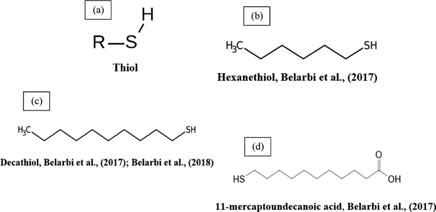
Chemical structures of some TLC inhibitors based on thiols.
Using different techniques, the effectiveness of decanethiol, hexanethiol, and 11-mercaptoundecanoic acid (Fig. 13b–d) for CO2 corrosion inhibition has been investigated (Belarbi et al., 2017). The results suggest the development of an adsorbed inhibitor film. Further tests were also conducted to assess the residence time. Decanethiol demonstrated very good inhibition characteristics and high persistence among the tested inhibitors. With the same added amount (100 ppmv), the 11-mercaptoundecanoic acid and decanethiol offered better protection than hexanethiol against TLC.
Belarbi et al. (2018) investigated the impact of the operating factors on the effectiveness of decanethiol (Fig. 13c) in TLC. The effects of hydrocarbon, monoethylene glycol (MEG), water condensation rates, and H2S were assessed. The investigation found that decanethiol was able to protect the steel samples exposed to TLC conditions at all tested gas temperatures and water condensation rates. The presence of 50 wt% MEG in the bulk aqueous phase did not affect the inhibition efficiency of decanethiol. It was able to decrease localized corrosion of carbon steel and change the morphology of corrosion on samples exposed to 30 ppm H2S. The performance of the decanethiol was further evaluated in the presence of heptane. In the presence of a non-polar solvent (heptane), there was no adsorption of thiols on the steel surface, leading to poor inhibition properties at the top of the line. Table 3 shows the thiol-based chemistry reported as TLC inhibitors. Test duration: 2 days Test solution: 1% NaCl condensation rate: 0.6 mL/m2/s Inhibitor concentration: 100, 400 ppmv Test duration: 3, 7 days Test solution: 1% NaCl, DI water pH: 4 condensation rate: 0.005, 0.12, 0.056, 0.90, 2.2 mL/m2/s Inhibitor concentration: 400 ppm H2S concentration: 30 ppm CR: Corrosion rate; IE%: Inhibition efficiency; DI: Deionized; WL: Weight Loss; SEM: Scanning Electron Microscopy; XPS: X-ray Photoelectron Spectroscopy; EDS: Energy-Dispersive X-ray Spectroscopy.
Corrosion Inhibitor
Metallurgy
Temperature and Pressure
Experimental Conditions
Maximum protection
Reference
Hexanethiol, decanethiol, and 11- mercaptoundecanoic acid
X65 Carbon steel
65 ± 2 °C; 66 × 103 Pa
Technique: WL, SEM, EDS, XPSCR: 0.02 mm/y IE%: 98%
Belarbi et al. (2017)
Decanethiol
X65 Carbon steel
40°, 65°, 80 °C, 1 bar
Technique: WL, SEM, EDSCR: ≤0.06 mm/y IE%: >87%
Belarbi et al. (2018)
3.4 Monoethylene glycol-based inhibitors
Monoethylene glycol (MEG) is an odorless, sweet-tasting, colorless, and viscous compound with the formula (CH2OH)2. MEG is often referred to as a hydrate inhibitor because of its application in the prevention of the formation of solid–gas hydrate in wet natural gas pipelines at low operating temperatures such as sea lines (Lehmann et al., 2014). It has been reported that MEG could be used as an inhibitor in CO2 corrosion when the CO2 partial pressure is very low. However, the use of corrosion control methods such as the application of pH stabilization would be required at higher CO2 partial pressure (Gulbrandsen and Morard, 1998). The use of MEG is cost-effective because the rich MEG which is initially injected into the flowline can undergo ‘reclamation’ which is a process of removing solids (non-volatile salts) that precipitated in the formation water, and produce a lean MEG which can be re-injected into the flowline (Lehmann et al., 2014).
MEG can be adsorbed on the steel surface, which hinders the steel from interacting with the corrosive environment (Ehsani, 2013). MEG can reduce the solubility of Fe ion, which in turn leads to saturation of Fe ion thus reducing the rate of corrosion (Svenningsen and Nyborg, 2014). In the TLC case, MEG has been reported to withhold the condensation rate by reducing the vapor pressure of the liquid phase of wet gas (Ehsani, 2013; Svenningsen and Nyborg, 2014). There are no sufficient studies on the impacts of MEG on the TLC, as most of the studies were conducted under the BLC conditions.
To evaluate the inhibition impact of MEG on the TLC, condensation rate measurements were used (Ehsani, 2013), since the water rate of condensation depends on the concentration of MEG in the bulk liquid and the temperature. The higher glycol concentration (or a lower rate of condensation) decreases the FeCO3 solubility and accelerates the formation of a protective film. This study concluded that the presence of 90% MEG is sufficient to decrease the condensation rate below the critical rate of 0.25 g/m2s and avoid TLC.
Ajayi (2015) studied the impact of MEG on carbon steel TLC in the presence of HAc. The investigation found that MEG partly neutralized the effects of HAc. Therefore, MEG could act as a pH adjuster to reduce the corrosion rate in production pipelines. The study assumed that the presence of MEG at top of the line reduced the partial pressure of water by adsorbing it from the gas phase, thereby lowering the dew point of the gas and reducing the condensation rate, and consequently the TLC rate.
A glycol/water co-condensation model was developed to study the impact of MEG on TLC (Guo et al., 2017, 2016). Long-term experimental results indicated an inhibitory impact of MEG on the TLC rate and localized corrosion. The corrosion results are due to the impact of MEG on the rate of condensation and MEG concentration in the condensing phase.
The impact of MEG on the condensation and TLC behavior was thoroughly investigated (Islam et al., 2018b). The study demonstrated that the corrosion rates were reduced with increasing bulk MEG concentrations. This points out that the MEG co-condensation and the reduction of the condensation rate are key elements in TLC reduction. However, the latter is slightly more central. Under the immersion conditions, no localized corrosion was noticed, which highlights the impact of the condensation process on localized TLC.
In a recent study by Widyanto and Suputra Wiguna (2019) the impact of MEG on the TLC rate of low carbon steel in an acidic environment with high temperature was studied. After adding MEG into the solution of HAc at 50 and 70 °C, the TLC rate was substantially reduced. The mechanism is a result of the reduced condensation rate, which in turn reduced the production of the electrolyte necessary for the corrosion reaction. The study concluded that all the concentrations of MEG investigated have a significant inhibiting impact on the TLC rate. Table 4 shows a summary of reported TLC inhibitors based on monoethylene glycol. Test duration: 18 h Test solution: DI-Water Inhibitor concentration: 50, 90% vol. Technique: autoclave, FTIR Test duration: 1–5 days Test solution: 1% NaCl Condensation rate: moderate HAc concentration: 1000 ppm Inhibitor concentration: 1000, 5000 ppm Technique: WL, OCP, LPR, EIS, PDP, SEM, XRD, XPS Test duration: 21 days Test solution: MEG/water solution with CO2 Inhibitor concentration: 50, 70, 90 wt% Gas velocity, Vgas: 1–3 m/s Techniques: large scale flow loop Test duration: 10, 17, 30 days Test solution: MEG/water solution with CO2 Inhibitor concentration: 10, 50, 80 wt% pH: 5.6 Techniques: WL, SEM, EDS, Raman spectroscopy Test duration: 2, 4, 6 days Test solution: 2000 ppm HAc + 50%v MEG Technique: chamber simulate TLC condition, light microscope, macro camera IE%: Inhibition efficiency; DI: Deionized; WL: Weight Loss; FTIR: Fourier-transform infrared spectroscopy; LPR: Linear Polarization Resistance; SEM: Scanning Electron Microscopy; EDS: Energy-Dispersive X-ray Spectroscopy; XRD: X-ray Diffraction; XPS: X-ray Photoelectron Spectroscopy; PDP: Potentiodynamic Polarization; OCP: Open Circuit Potential; EIS: Electrochemical Impedance Spectroscopy.
Corrosion Inhibitor
Metallurgy
Temperature and Pressure
Experimental Conditions
Maximum protection
Reference
MEG
Carbon steel
60°, 90°, 120 °C; 20 bar
Condensation rate: 0.2 g/m2s with 90% MEG at 120 °C
Ehsani (2013)
MEG
Carbon steel
60 °C; 0.81 bar
IE% (WL): 74%
Ajayi (2015)
MEG
X65 Carbon steel
42 °C; 3 bar
IE%: 70%
Guo et al. (2017, 2016)
MEG
1030 Carbon steel
55 ± 1 °C
IE%: 59%
Islam et al. (2018b)
MEG
Low carbon steel
50°, 70 °C
IE%: 77.65%
Widyanto, Suputra Wiguna (2019)
4 Existing knowledge gaps on TLC
Although there are many studies on TLC mechanism and mitigation, there are some knowledge gaps still remaining to be explored. In this section, some knowledge gaps are identified and discussed.
-
Most reported TLC inhibitors have been tested in brine solutions that have low concentrations of dissolved solids, such as, NaCl, and ignored the highly aggressive brine solutions that have a high concentration of total solids and the presence of light hydrocarbons.
-
The reported TLC inhibitors have focused mainly on carbon steel class. Not much attention is given to other iron-based alloys that are widely used at high temperatures and high pressures, such as Cr-steel, duplex stainless steels, ferritic, austenitic, and martensitic, etc.
-
Most corrosion inhibitors for the TLC inhibition are amines, imidazoline, thiol, and glycol. No important attempts have been made to study other chemical compounds.
-
There is a gap between short term lab studies on single inhibitors under static or contrived flow conditions and the practical, complex flow, multiphase electrolyte, multiple inhibitor conditions found in practice.
-
Fundamental investigations are often not performed to determine the sort of adsorption (whether physical or chemical) as well as adsorption/desorption kinetics. This restricts the field of the validity of this type of mitigation. The effect of the steel surface properties (roughness, scale, existence of oxide or other corrosion product layers) on the effectiveness of the TLC inhibitors has not been studied.
-
When field data is available, the corrosion inhibitor compounds are usually kept confidential. Even when a paper has been published with an inhibition efficiency of about 70% in a field trial (Punpruk et al., 2010), the disclosed amount of information is not usually enough for further research.
-
Compatibility tests of volatile inhibitors with other chemicals injected into the field are required to ensure that no process is set during field testing. The published literature lacks such tests.
-
The development of an effective TLC inhibitor formulation usually involves mixing different types of chemical compounds. They should be evaluated over an interval known as their shelf life. The published literature lacks such reports.
-
TLC inhibitors are generally not applied directly to the steel; they are rather added to pre-corroded steel surfaces. This means that in developing TLC inhibitors, the inhibitor-surface interaction of previously corroded steel must be taken into account. This is accomplished through examining the interactions between the FeCO3 scales, and the inhibitors, as the real mechanism of this reaction remains unclear up till now.
-
Corrosion environments often contain measured quantities of H2S which can form an FeS scale. Yet, few studies investigated the impact of such FeS scales on the effectiveness of the inhibitors.
-
Using a foam medium to transport the corrosion inhibitor to the top of the pipes is a very good potential; however, numerous challenges still need to be overcome before being used in real-life applications. Thus, optimizing the type and concentration of corrosion inhibitor still needs further study.
-
The scarcity of stop-start and other dynamic flow evaluation studies; steady state flow or static electrolyte conditions are rarely of relevance-yet widely practiced by academic laboratories.
5 Future research directions
This section discusses some of the challenges and future research directions to be pursued in an attempt to develop effective mitigation for TLC using corrosion inhibitors.
-
The key challenge in the development of VCIs as TLC inhibitors is to utilize the right molecules of high corrosion inhibition efficiency. Compatibility with other applied chemicals, dissolution in the hydrocarbon and water phases, health and safety concerns, and eco-friendly processes must be taken into account.
-
When developing the TLC inhibitor formulations, it is recommended that inhibitor formulation should contain at least a pH stabilizer, such as MDEA, which can increase the solution pH level to further promote the formation of protective FeCO3 film.
-
Most of the TLC inhibitors reported with high inhibition efficiencies were obtained only in the case of using high concentrations (≥500 ppm). This is an area of novel research for the development of corrosion inhibitor formulations that can be effective for TLC by using low concentrations.
-
Further studies can be done to determine the shelf life of the inhibitor films under different flow conditions and corrosive gases, and further tests can be conducted to test promising new technologies that include inhibitor foams and the application of other chemicals that can enhance the adhesion of active particles to the pipes.
-
The duration of the TLC experiments could be extended to a longer period such as 1 month, 3 months, and even 6 months to further study time-dependent of the inhibition of the suggested formulations on corrosion rate.
-
Using powerful measurement-methods such as x-ray photoelectron spectroscopy (XPS), transmission electron microscopy (TEM), Raman Microscopy and atomic force microscopy (AFM) for surface characterization is an important research area to understand the inhibitor-metal interaction. Such characterization offers new mechanisms of interaction like chemical complexation with metal atoms or physical adsorption of inhibitor molecules.
6 Conclusion
TLC is a serious challenge in the oil and gas industry. This type of corrosion occurs exclusively in stratified flow regimes, and wet gas transportation because of the condensation of water that is filled with corrosive gases. One of the most effective methods to mitigate TLC is the use of chemical corrosion inhibitors. This work has reviewed the causes, mechanisms, and mitigation methods using mainly corrosion inhibitors reported from scientific research publications for TLC from 1990 to 2020. Nitrogen-based compounds such as amines and imidazolines are the most widely used inhibitor chemistries. Nevertheless, thiol-based compounds used in recent years have shown good inhibition efficiencies in various conditions and are considered promising corrosion inhibitors for TLC. Furthermore, we have documented some knowledge gaps concerning TLC inhibitors and highlighted potential future research areas.
CRediT authorship contribution statement
Aisha H. Al-Moubaraki: Investigation, Methodology, Writing - review & editing. I.B. Obot: Conceptualization, Investigation, Methodology, Writing - review & editing.
Declaration of Competing Interest
The authors declare that they have no known competing financial interests or personal relationships that could have appeared to influence the work reported in this paper.
References
- Ajayi, F., Lyon, S., 2013. Detrimental effects of acetic acid on corrosion of carbon steel pipelines transporting wet gas. In: 37th Annu. SPE Niger. Int. Conf. [NAICE] (Lagos, Niger. 7/30/2013-8/1/2013) Proc.
- Ajayi, F.O., 2015. Mitigating corrosion risks in oil and gas equipment by electrochemical protection: Top of the line corrosion. PhD diss., The University of Manchester, UK.
- Alberta Energy Regulator, 2013. Report 2013-B : Pipeline Performance in Alberta, 1990-2012 1–104.
- Amri, J., Gulbrandsen, E., Nogueira, R.P., 2011. Role of acetic acid in CO2 top of the line corrosion of carbon steel. In: NACE - International Corrosion Conference Series, Paper No.11329.
- Amri, J., Gulbrandsen, E., Nogueira, R.P., 2010. Propagation and arrest of localized attacks in carbon dioxide corrosion of carbon steel in the presence of acetic acid. Corrosion 66, 035001-1-035001–7. https://doi.org/10.5006/1.3360906.
- The effect of acetic acid on the pit propagation in CO2 corrosion of carbon steel. Electrochem. Commun.. 2008;10:200-203.
- [CrossRef] [Google Scholar]
- Volatile inhibitors for CO2 corrosion. In: NACE - International Corrosion Conference Series. 1998.
- [Google Scholar]
- Anuar, S.B.S., Ismail, M.C., Raja, P.B., Rahman, N.A. i. B.A., 2016. Condensation rate effect on top of line corrosion in CO2 environment. ARPN J. Eng. Appl. Sci. 11, 12058–12063.
- Asher, S.L., Sun, W., Ojifinni, R., Pacheco, J., Li, C., Nelson, J., Ling, S., 2012. Top of the line corrosion prediction in wet gas pipelines. In: NACE International, Corrosion/2012, 11–15 March, Salt Lake City, Utah, NACE-2012-1303. pp. 2353–2360.
- A comprehensive review on internal corrosion and cracking of oil and gas pipelines. J. Nat. Gas Sci. Eng.. 2019;71:1-25.
- [CrossRef] [Google Scholar]
- Decanethiol as a corrosion inhibitor for carbon steels exposed to aqueous CO2. Corrosion. 2019;75:1246-1254.
- [CrossRef] [Google Scholar]
- Belarbi, Z., Farelas, F., Singer, M., Nešić, S., 2016a. Role of amine in the mitigation of CO2 top of the line corrosion. In: NACE International, Corrosion /2016, 6–10 March, Vancouver, British Columbia, Canada, NACE-7274.
- Role of amines in the mitigation of CO2 top of the line corrosion. Corrosion. 2016;72:1300-1310.
- [CrossRef] [Google Scholar]
- Belarbi, Z., Farelas, F., Young, D., Singer, M., Nesic, S., 2018. Effect of operating parameters on the inhibition efficacy of decanethiol. In: NACE - International, Corrosion/2018, 15–19 April, Phoenix, Arizona, USA, NACE-10823.
- Thiols as volatile corrosion inhibitors for top-of-the-line corrosion. Corrosion. 2017;73:892-899.
- [CrossRef] [Google Scholar]
- Brown, B., Lee, K.L., Nesic, S., 2003. Corrosion in multiphase flow containing small amounts of H2S. In: NACE - International, Corrosion Conference Series, Paper No. 03341.
- Camacho, A., Singer, M., Brown, B., Nesic, S., 2008. Top of the line corrosion in H2S/CO2 environments. In: NACE - International, Corrosion Conference Series, Paper No. 08470. pp. 084701–0847022.
- Best management practices: mitigation of internal corrosion in oil effluent pipeline systems. Can. Assoc. Pet. Prod. 2009:1-29.
- [Google Scholar]
- Chen, Y., Zhang, L., Qin, H., Xu, L., Lu, M., 2011. Effects of temperature on CO2 top of line corrosion of pipeline steel. In: NACE International, Corrosion/2011, 13-17 March, Houston, Texas, NACE-11327.
- An Introduction to Organosulfur Chemistry. John Wiley and Sons; 1996.
- Crolet, J.L., Thevenot, N., Dugstad, A., 1999. Role of free acetic acid on the CO2 corrosion of steels. In: NACE International, Corrosion/99, 25–30 April, San Antonio, Texas, NACE-99024.
- Role of conductive corrosion products in the protectiveness of corrosion layers. Corrosion. 1998;54:194-203.
- [CrossRef] [Google Scholar]
- de Waard, C., Lotz, U., 1993. Prediction of CO₂ corrosion of carbon steel. In: NACE-International, Corrosion/93, Paper No: 93069.
- Formation, investigation and characterization of self-assembled monolayers of 5-methyl-1, 3, 4-thiadiazole-2-thiol in corrosion protection of copper in neutral media. Adv. Appl. Sci. Res.. 2015;6:28-41.
- [Google Scholar]
- Dugstad, A., 2014. Top of line corrosion - Impact of MEG and organic acid in the gas phase. In: NACE International, Corrosion/2014, 9–13 March, San Antonio, Texas, USA, NACE-2014-4382.
- Dugstad, A., 1992. The importance of FeCO3 supersaturation of carbon steel. In: Corrosion/92, Proc. Corrosion, Houston, TX, Paper. 14.
- Influence of Monoethylene Glycol (MEG) on the Corrosion Inhibition of Wet-Gas Flow Lines. Australia: Curtin University; 2013.
- Esmaeely, S.N., Zhang, W., Brown, B., Singer, M., Nešić, S., 2017. Localized corrosion of mild steel in marginally sour environments. In: Corrosion. National Assoc. of Corrosion Engineers International, pp. 1098–1106. https://doi.org/10.5006/2422.
- Estavoyer, M., 1981. Corrosion problems at lack sour gas field, H2S corrosion in oil & gas production. In: NACE International. p. 905.
- Fajardo, V., Canto, C., Brown, B., Nesic, S., 2007. Effect of organic acids in CO2 corrosion. In: NACE - International, Corrosion Conference Series, Paper No. 07319. pp. 073191–0731918. https://doi.org/10.1149/ma2006-02/16/837.
- Frenier, W.W., Wint, D., 2014. Multifaceted approaches for controlling top of line corrosion (TLC) in pipelines. In: Soc. Pet. Eng. - SPE Int. Conf. Exhib. Oilf. Corros. 2014 New Challenges a New Era 65–80. https://doi.org/10.2118/169630-ms.
- Speciation and electrochemistry of brines containing acetate ion and carbon dioxide. J. Electroanal. Chem.. 2002;538:285-297.
- [CrossRef] [Google Scholar]
- Investigation of carbon dioxide corrosion of mild steel in the presence of acetic acid - Part 1: Basic mechanisms. Corrosion. 2007;63:178-186.
- [CrossRef] [Google Scholar]
- Gulbrandsen, E., Morard, J.H., 1998. Why does glycol inhibit CO2 corrosion?. In: NACE - International Corrosion /98, 22–27 March, San Diego, California, NACE-98221.
- Gunaltun, Y., Piccardino, R., Vinazza, D., 2006. Interpretation of MFL and UT inspection results in case of top of line corrosion. In: NACE - International, Corrosion Conference Series, Paper No. 6170.
- Gunaltun, Y., Pou, T.E., Singer, M., Duret, C., Espitalier, S., 2010. Laboratory testing of volatile corrosion inhibitors. In: NACE - International, Corrosion/2010, 14–18 March, San Antonio, Texas, NACE-10095.
- Gunaltun, Y.M., Belghazi, A., 2001. Control of top of line corrosion by chemical treatment. In: NACE International, Corrosion/2001, 11–16 March, Houston, Texas, NACE-01033.
- Gunaltun, Y.M., Larrey, D., 2000. Correlation of cases of top of line corrosion with calculated water condensation rates. In: NACE International, Corrosion/2000, 26–31 March, Orlando, Florida, NACE-00071.
- Gunaltun, Y.M., Supriyatman, D., Achmad, J., 1999. Top of line corrosion in multiphase gas lines. A case history. In: NACE International, Corrosion/99, 54th Annual Conference and Exposition, San Antonio, Texas, USA, 25–30 April. NACE 99036.
- A glycol/water co-condensation model to investigate the influence of monoethylene glycol on top-of-the-line corrosion. Corrosion. 2017;73:742-755.
- [CrossRef] [Google Scholar]
- Guo, S., Farelas, F., Singer, M., 2016. Effect of monoethylene glycol on sweet top of the line corrosion. In: NACE International, Corrosion/2016, 6–10 March, Vancouver, British Columbia, Canada, NACE-7891.
- 5-Amino-1, 3, 4-thiadiazole-2-thiol corrosion current density and adsorption thermodynamics on ASTM A-890-1B stainless steel in a 3.5% NaCl solution. J. Chil. Chem. Soc.. 2009;54:123-128.
- [Google Scholar]
- Hedges, B., McVeigh, L., 1999. The role of acetate in CO2 corrosion: The double whammy. In: NACE International, Corrosion/99, 25–30 April, San Antonio, Texas, NACE-99021.
- Hinkson, D., Singer, M., Zhang, Z., Nesic, S., 2008. A Study of the chemical composition and corrosivity of the condensate in top of the line corrosion. In: NACE - International, Corrosion Conference Series-NACE 08466. pp. 084661–0846615.
- Islam, M.M., 2017. An Investigation on the top-of-the-line corrosion using novel methods. PhD diss., Curtin University.
- Study of the top-of-the-line corrosion using a novel electrochemical probe. Corrosion. 2018;74:588-598.
- [CrossRef] [Google Scholar]
- Corrosion of carbon steel under condensing water and monoethylene glycol. Corros. Sci.. 2018;143:10-22.
- [CrossRef] [Google Scholar]
- Jaal, R.A., Ismail, C., Ariwahjoedi, B., 2014. A Review of CO2 corrosion inhibition by imidazoline-based inhibitor. MATEC Web Conf. 13, 05012-1-05012–4. https://doi.org/10.1051/C.
- Jauseau, N., Farelas, F., Singer, M., Nešić, S., 2018a. Investigation of the applicability of droplet transport for top of the line corrosion mitigation. In: NACE - International, Corrosion/2018, 15–19 April, Phoenix, Arizona, USA, NACE-11493.
- Investigation of the role of droplet transport in mitigating top of the line corrosion. Corrosion. 2018;74:873-885.
- [CrossRef] [Google Scholar]
- Jenkins, A., Gilbert, I., 2012. Development of a top-of-line corrosion inhibitor and a top-of-line corrosion test method. In: NACE - International, Corrosion/2012, 11–15 March, Salt Lake City, Utah, NACE-2012-1275.
- Jenkins, A., Gilbert, I., Kamaruzaman, A., Lone, A., 2018. Top-of-line corrosion inhibition and proposal of an inhibition mechanism. In: NACE - International, Corrosion/2018, 15–19 April, Phoenix, Arizona, USA, NACE-11117.
- A mixture of dicyclohexylamine and oleylamine as a corrosion inhibitor for mild steel in NaCl solution saturated with CO2 under both continual immersion and top of the line corrosion. J. Serbian Chem. Soc.. 2012;77:1047-1061.
- [CrossRef] [Google Scholar]
- A Novel method to mitigate the top-of-the-line corrosion in wet gas pipelines by corrosion inhibitor within a foam matrix. Corrosion. 2013;69:186-192.
- [CrossRef] [Google Scholar]
- Jevremović, I., Singer, M., Achour, M., Blumer, D., Baugh, T., Misković-Stanković, V., Nešić, S., 2012b. A Novel method to mitigate the top of the line corrosion in wet gas pipelines by corrosion inhibitor within a foam matrix. In: NACE - International, Corrosion Conference Series, NACE-C2012-0001403.
- Evaluation of a novel top-of-the-line corrosion (TLC) mitigation method in a large-scale flow loop. Corrosion. 2015;71:389-397.
- [CrossRef] [Google Scholar]
- Jevremović, I., Singer, M., Achour, M., Miskovic-Stankovic, V., Nešić, S., 2013b. Evaluation of a novel top-of-the-line corrosion (TLC) mitigation method in a large-scale flow loop. In: NACE - International, Corrosion Conference Series, NACE-2321.
- Development of an effective method for internal pipeline corrosion control in the presence of CO2. Zast. Mater.. 2016;57:195-204.
- [CrossRef] [Google Scholar]
- John, D., Capelli, L., Kinsella, B., Bailey, S., 2009. Top of the line corrosion control by chemical treatment. In: NACE - International, Corrosion/2009, 22–26 March, Atlanta, Georgia, NAC-09286.
- Jones, D., 1992. The technology and evaluation of corrosion. In: Principles and Prevention of Corrosion. pp. 1–35.
- Joosten, M.W., Kolts, J., Hembree, J.W., Achour, M., 2002. Organic acid corrosion in oil and gas production. In: NACE International, Corrosion/2002, 7–11 April, Denver, Colorado, NACE-02294.
- Determination of amines used in the oil and gas industry (upstream section) by ion chromatography. J. Chromatogr. A. 1999;850:289-295.
- [CrossRef] [Google Scholar]
- Koch, G.H., Brongers, M.P.H., Thompson, N.G., Virmani, Y.P., Payer, J.H., 2002. Corrosion cost and preventive strategies in the United States (FHWA-RD-01-156).
- Lehmann, M.N., Lamm, A., Nguyen, H.M., Bowman, C.W., Mok, W.Y., Salasi, M., Gubner, R., 2014. Corrosion inhibitor and oxygen scavenger for use as MEG additives in the inhibition of wet gas pipelines. In: Proceedings of the Annual Offshore Technology Conference. pp. 3292–3312. https://doi.org/10.4043/25070-ms.
- The effect of acetic acid and acetate on CO2 corrosion of carbon steel. Anti-Corrosion Methods Mater.. 2008;55:130-134.
- [CrossRef] [Google Scholar]
- Martin, R.L., 2009. Control of top-of-line corrosion in a sour gas gathering pipeline with corrosion inhibitors. In: NACE - International, Corrosion/2009, 22–26 March, Atlanta, Georgia, NACE-09288.
- Martin, R.L., 1997. Inhibition of vapor phase corrosion in gas pipelines. In: NACE - International, Corrosion Conference Series, Houston, TX, Paper. 97337.
- Corrosion resistance and structure of thiol self-assembly super thin film on zinc coated steel sheet. ISIJ Int.. 2011;51:108-114.
- [CrossRef] [Google Scholar]
- Méndez, C., Singer, M., Camacho, A., Hernández, S., Nesic, S., Gunaltun, Y., Joosten, M., Sun, Y., Gabbetta, P., 2005. Effect of acetic acid, pH and MEG on the CO2 top of the line corrosion. In: NACE - International, Corrosion Conference Series, NACE-05278.
- Vapor corrosion inhibitors for Top-of-the-line corrosion. Mater. Perform.. 2013;52:56-60.
- [Google Scholar]
- Nafday, O.A., Nesic, S., 2005. Iron carbonate scale formation and CO2 corrosion in the presence of acetic acid. In: NACE - International, Corrosion Conference Series, NACE-05295.
- Key issues related to modelling of internal corrosion of oil and gas pipelines - A review. Corros. Sci. 2007
- [CrossRef] [Google Scholar]
- A mechanistic model for carbon dioxide corrosion of mild steel in the presence of protective iron carbonate films - Part 3: Film growth model. Corrosion. 2003;59:616-628.
- [CrossRef] [Google Scholar]
- An Electrochemical model for prediction of corrosion of mild steel in aqueous carbon dioxide solutions. Corros.. 1996;52:280-294.
- [CrossRef] [Google Scholar]
- Nešić, S., Sun, W., 2010. Corrosion in acid gas solutions. In: Shreir’s Corrosion, Tony J.A. Richardson, (Ed.) Elsevier, Oxford. pp. 1270-1298.
- Nyborg, R., Dugstad, A., 2007. Top of line corrosion and water condensation rates in wet gas pipelines. In: NACE International, Corrosion/2007, 11–15 March, Nashville, Tennessee, NACE-07555. pp. 075551–0755510.
- Simplified calculation of CaCO3 saturation at high temperatures and pressures in brine solutions. JPT, J. Pet. Technol.. 1982;34:1583-1590.
- [CrossRef] [Google Scholar]
- Oehler, M., 2012. Top-of-the-line corrosion control by continuous chemical treatment. PhD diss., Curtin University, Perth, Australia.
- Oehler, M.C., Bailey, S.I., Gubner, R., Gough, M., 2012. Testing of generic volatile inhibitor compounds in different top-of-the-line corrosion laboratory test methods. In: NACE - International, Corrosion/2012, 11–15 March, Salt Lake City, Utah, NACE-2012-1483.
- Ojifinni, R.A., Li, C., 2011. A parametric study of sweet top-of-line corrosion in wet gas pipelines. In: NACE International, Corrosion/2011, 13–17 March, Houston, Texas, NACE-11331.
- Effect of acetic acid on CO2 corrosion of carbon steel in vapor-water two-phase horizontal flow. Chem. Eng. Comm.. 2007;194:141-157.
- [CrossRef] [Google Scholar]
- Corrosion inhibition of offshore oil and gas production facilities using organic compound inhibitors - A review. J. Mol. Liq.. 2017;248:775-808.
- [CrossRef] [Google Scholar]
- Olsen, S., Dugstad, A., 1991. Corrosion under dewing conditions. In: Corrosion/91, Paper No 472, NACE, Houston, Texas, pp. 1–13.
- Patai, S., 2010. The Chemistry of The Thiol Group. Wiley, London. https://doi.org/10.1002/9780470771310.
- Internal inspection of wet gas lines subject to top of line corrosion. Corros./NACE Int. 2004:1-10.
- [Google Scholar]
- Influence of Water/Hydrocarbons Co-Condensation On Top of the Line Corrosion. USA: Institute for Corrosion and Multiphase Technology, Ohio University; 2012.
- Pojtanabuntoeng, T., Singer, M., Nesic, S., 2012. Top-of-the-line corrosion in the presence of hydrocarbon co-condensation in flowing condition. In: NACE International, Corrosion/2012, 11–15 March, Salt Lake City, Utah, NACE-2012-1534. pp. 4305–4317.
- Pots, B.F.M., Hendriksen, E.L.J.A., 2000. CO2 corrosion under scaling conditions - The special case of top-of-line corrosion in wet gas pipelines. In: NACE - International Corrosion Conference Series.
- Pots, B.F.M., John, R.C., Rippon, I.J., Thomas, M.J.J.S., Kapusta, S.D., Girgis, M.M., Whitham, T., 2002. Improvements on de waard-milliams corrosion prediction and applications to corrosion management. In: NACE - International Corrosion Conference Series, Paper No. 02235.
- Punpruk, S., Thammachart, M., Gunaltun, Y., 2010. Field testing of volatile corrosion inhibitors and evaluation of batch treatment efficiency by cooled probe. In: NACE - International Corrosion /2010, 14–18 March, San Antonio, Texas.
- Corrosion inhibition of copper by selected thiol compounds. ECS Trans.. 2008;13:123-132.
- [CrossRef] [Google Scholar]
- Ramachandran, S., Jovancicevic, V., Rodgers, P., Ahmed, I., Al-Waranbi, M., 2013. A New top-of-the-line corrosion inhibitor to mitigate carbon dioxide corrosion in wet gas systems. In: NACE - International, Corrosion/2013, 17–21 March, Orlando, Florida, NACE-2274.
- Web-based national corrosion cost inventory system for Saudi Arabia. Anti-Corrosion Methods Mater.. 2014;61:72-92.
- [CrossRef] [Google Scholar]
- Ruschau, G.R., Al-Anezi., M.A., 2003. Oil and gas exploration and production. In: Retrieved from Http:/Corrosionda. Com/Prodmanu/Oilgas/Index. Htm.
- Sadek, M.M., 2013. Top-of-line corrosion prediction in offshore pipelines. Civ. Eng. Program. Univ. Teknol. PETRONAS.
- Shant, J.R., Barker, R., Neville, A., 2017. Variation of top of line corrosion rates at different positions in pipe. In: ASME 2017 India Oil and Gas Pipeline Conference, IOGPC 2017. https://doi.org/10.1115/IOGPC20172438.
- Shen, M., Furman, A., Kharshan, R., Whited, T., 2013. Development of corrosion inhibitors for prevention of top of the line corrosion (TLC). In: NACE - International, Corrosion/2013, Orlando, FL, NACE-2509.
- Study of the localized nature of top of the line corrosion in sweet environment. Corrosion. 2017;73:1030-1055.
- [CrossRef] [Google Scholar]
- Singer, M., 2013. Study and modeling of the localized nature of top of the line corrosion. PhD dissertation, Ohio University, Ohio, USA.
- Singer, M., 2011. Top of the line corrosion in sour environment - Study of the controlling parameters. In: 18th International Corrosion Congress 2011, Paper 80.
- Singer, M., Camacho, A., Brown, B., Nešić, S., 2011. Sour top-of-The-line corrosion in the presence of acetic acid. Corrosion 67, 085003-1-085003–16. https://doi.org/10.5006/1.3615805.
- CO2 top-of-the-line corrosion in presence of acetic acid: a parametric study. Corrosion. 2013;69:719-735.
- [CrossRef] [Google Scholar]
- Singer, M., Nesic, S., Gunaltun, Y., 2004. Top of the line corrosion in presence of acetic acid and carbon dioxide. In: NACE Meeting Papers, Paper No. 04377.
- Singh, B., Krishnathasan, K., 2009. Pragmatic effects of flow on corrosion prediction. In: NACE - International, Corrosion Conference Series, Paper No: 09275.
- Smith, S.N., 2011. Discussion of the history and relevance of the CO2/H2S ratio. In: NACE - International, Corrosion Conference Series, Paper No. 11065.
- Smith, S.N., 1993. A proposed mechanism for corrosion in slightly sour oil and gas production. In: 12th Intl. Corrosion Congr.: Corrosion Control for Low-Cost Reliability Conference.
- Smith, S.N., Joosten, M.W., 2006. Corrosion of carbon steel by H2S in CO2 containing oilfield environments. In: NACE - International, Corrosion Conference Series, NACE-06115.
- Son, A.J., 2004. Pitfalls in monitoring sweet corrosion inhibition using residual analysis techniques. In: NACE International, Corrosion/2004, 28 March-1 April, New Orleans, Louisiana, NACE-04373.
- Thiol compounds as corrosion inhibitors of carbon steel (XC 38) in sodium chloride medium. Mater. Corros.. 1992;43:406-414.
- [CrossRef] [Google Scholar]
- Sun, W., 2006. Kinetics of iron carbonate and iron sulfide scale formation in CO2/H2S corrosion. PhD diss. Chem. Eng., Ohio University, USA.
- Sun, W., Nesic, S., 2007. A Mechanistic model of H2S corrosion of mild steel. In: NACE - International, Corrosion Conference Series, Paper No. 07655.
- Sun, Y.H., Hong, T., Jepson, W.P., 2001. Corrosion under wet gas conditions. In: NACE - International, Corrosion Conference Series-Paper No. 01034.
- Svenningsen, G., 2017. Sour top of line corrosion testing with methanol. In: NACE - International, Corrosion Conference Series, Paper No. 9337.
- Svenningsen, G., Foss, M., Nyborg, R., Fukagawa, H., Kurniawan, I., 2013. Top of line corrosion with high CO2 and organic acid. In: NACE International, Corrosion/2013, 17–21 March, Orlando, Florida, NACE-2013-2591.
- Svenningsen, G., Nyborg, R., 2014. Modeling of top of line corrosion with organic acid and glycol. In: NACE International, Corrosion/2014, 9–13 March, San Antonio, Texas, USA, NACE-2014-4057.
- Tan, Y., Fwu, Y., Bhardwaj, K., Bailey, S., Gubner, R., 2010. Review of critical issues in carbon dioxide corrosion testing and monitoring techniques. In: NACE International, Corrosion/2010, 14–18 March, San Antonio, Texas, NACE-10155.
- Thomson, H., McCall, M., Stephens, A., Simpson, C.M.E., Ray, J., Frigo, D.M., Graham, G.M., 2016. Development of new laboratory test methods for measuring top of the line corrosion and assessing corrosion inhibitor performance, in: Society of Petroleum Engineers - SPE International Oilfield Corrosion Conference and Exhibition. https://doi.org/10.2118/179940-ms.
- Van Hunnik, E.W.J., Pots, B.F.M., Hendriksen, E.L.J.A., 1996. The formation of protective FeCO3 corrosion product layers in CO2 corrosion. In: NACE-International, Corrosion/96, 24–29 March, Denver, Colorado, NACE-96006.
- Vedapuri, D., Kang, C., Dhanabalan, D., Gopal, M., 2000. Inhibition of multiphase wet gas corrosion. In: NACE - International, Corrosion/2000, 26–31 March, Orlando, Florida, NAC-00043.
- Carbon-steel corrosion in multiphase slug flow and CO2. Corros. Sci.. 2006;48:2363-2379.
- [CrossRef] [Google Scholar]
- Vitse, F., 2002. Experimental and theoretical study of the phnomena of corrosion by carbon dioxide under dewing conditions at the top of a horizontal pipeline in the presence of a non-condensable gas. PhD diss. Ohio University, USA.
- Vitse, F., Alam, K., Gunaltun, Y., De Torreben, D.L., Duchet-Suchaux, P., 2002. Semi-empirical model for prediction of the top-of-the-line corrosion risk. In: NACE - International, Corrosion Conference Series, Paper No. 02245.
- Mechanistic model for the prediction of top-of-the-line corrosion risk. Corrosion. 2003;59:1075-1084.
- [CrossRef] [Google Scholar]
- The effect of mono ethylene glycol on the top of line corrosion rate of low carbon steel in acetic acid and elevated temperature environment. Heliyon. 2019;5
- [CrossRef] [Google Scholar]
- Yaakob, N., Farelas, F., Singer, M., Young, D., 2016. Localized top-of-line corrosion in marginally sour environments. In: NACE - International, Corrosion Conference Series, Paper No. 7695.
- Zhang, Z., 2008. A Study of top of the line corrosion under dropwise. PhD diss., Chemical Engineering of Ohio University.
- Study on the compound of imidazoline corrosion inhibitor. In: IOP Conference Series: Earth and Environmental Science. Institute of Physics Publishing; 2018. p. :1-10.
- [CrossRef] [Google Scholar]


