

Translate this page into:
Improved self-healing performance of polymeric nanocomposites reinforced with talc nanoparticles (TNPs) and urea-formaldehyde microcapsules (UFMCs)
⁎Corresponding author. shakoor@qu.edu.qa (Rana Abdul Shakoor)
-
Received: ,
Accepted: ,
This article was originally published by Elsevier and was migrated to Scientific Scholar after the change of Publisher.
Abstract
Abstract
The present work reports the self-healing performance of the epoxy based polymeric nanocomposite coatings containing different concentrations (1 and 3 wt%) of talc nanoparticles (TNPs) modified with sodium nitrate (NaNO3), and a fixed amount (5 wt%) of urea-formaldehyde microcapsules (UFMCs) encapsulated with linseed oil (LO). The polymeric nanocomposites were developed, coated on polished steel substrates, and their structural, thermal, and self-healing characteristics were investigated using various techniques. The successful loading (∼wt 10%) of NaNO3 into TNPs, which can be ascribed to the involvement of physio-chemical adsorption mechanism, is validated and proceeds without altering the TNPs parent lamellae structure. The performed tests elucidated that the self-release of the corrosion inhibitor (NaNO3) from TNPs is sensitive to the pH of the solution and immersion time. In addition, the release of the linseed oil (self-healing agent) from UFMCs in response to the external damage was found to be a time-dependent process. The superior self-healing and corrosion inhibition performance of the protective polymeric nanocomposites coatings containing 3 wt% TNPs and UFMCs/LO are proven using the electrochemical impedance spectroscopy (EIS) studies. A careful selection of smart carriers, inhibitor, and self-healing agent compatible with polymeric matrix has enabled to attain decent self-healing and convincing corrosion inhibition efficiency of 99.9% and 99.5%, respectively, for polymeric nanocomposites coatings containing 3 and 1 wt% TNPs, making them attractive for many industrial applications.
Keywords
Nanoparticles
Nanocomposites
Corrosion inhibitor
Self-healing coatings
Electrochemical Impedance Spectroscopy

1 Introduction
Corrosion has been proclaimed as one of the most destructive phenomena, which not only results in a substantial economic loss but can also be life-threatening and cause massive environmental problems. The primary reason associated with the corrosion process is the decrease in the Gibbs free energy of the system, which causes the metal to return to its natural lower energy state-oxide form (Gilbert, 1978). One of the common ways to protect the materials from the deleterious effect of corrosion is to form a physical barrier avoiding direct contact between the material and the external environment. This physical barrier can be damaged or weakened during operational use or due to the inherent porosity of the coating matrix leading to the further propagation of scratch, penetration of corrosive species, and thus degradation of materials. The conception of a “smart” coating is more advanced and has been applied to functional coatings that can respond to certain stimuli generated by internal or external factors (Gilbert, 1978). In addition to the barrier, the coating itself must have sufficient capability to inhibit the corrosion process if the protective barrier is damaged by any means. Therefore, corrosion protection requires the use of anticorrosion pigments or corrosion inhibitors that protect the underlying metal. However, the direct addition of corrosion inhibitor into a matrix is not a good idea, as it may react with the matrix resulting in poor barrier properties and can cause damage to the coatings (Zahidah et al., 2017). The well-adopted approach is to load these active species into compatible carriers or reservoirs and their uniform dispersion into the composite matrix.
Numerous reservoirs or nanocontainers, including polymer microcapsules (Khan et al., 2019a, 2019b; Lang and Zhou, 2017), mesoporous inorganic materials (Borisova et al. (2012); Chenan et al. (2014); Vijayan and Al-Maadeed (2016)), porous and hollow particles and nanotubes (Habib et al., 2019; Ubaid et al., 2019a; Vijayan et al., 2016) have been reported in the literature. Several functionalities can be introduced into coatings using this approach. One of the most advanced strategies is the addition of self-healing functionality into polymeric capsules, which has been widely studied over a long period of time (Cho et al., 2009; Habib et al., 2019; Montemor and Ferreira, 2008; Skorb et al., 2009; Snihirova et al., 2010; Tedim et al., 2012). The smart coatings incorporated with self-healing agent and corrosion inhibitor not only heals the defect through a polymerizable agent but also inhibits corrosion at the corroding area due to the presence of a corrosion inhibitor (Brown et al., 2003; Snihirova et al., 2012). Various self-healing systems have been studied so far (Abdullayev and Lvov, 2010; Attaei et al., 2020a, Attaei et al., 2020b; Habib et al., 2019; Khan et al., 2019b; Nardeli et al., 2021, 2020a, 2020b; Qian et al., 2017; Taryba et al., 2011; Thakur and Kessler, 2015) The incorporation of urea-formaldehyde microcapsules (UFMCs) encapsulated with a suitable self-healing agent into the polymeric matrix is one of the promising strategies to repair the damage. The work of White et al. is well known in this field (White et al., 2001).
Recent literature is quite valuable with lots of contributions focusing on the encapsulation of various functional species claiming decent self-healing and improved corrosion inhibition abilities triggered by external stimuli such as pH, light, temperature, and mechanical damage (Habib et al., 2020;Habib et al., 2019; Khan et al., 2020; Nawaz et al., 2020a, 2020b). Montemor et al. (Montemor et al., 2009) modified silane coatings with cerium ions as an inhibiting agent, which provided effective healing to the steel. Szabó et al. (Szabó et al., 2015a) synthesized urea- resorcinol formaldehyde microcapsules loaded with linseed oil and octadecylamine (OCD) as a corrosion inhibitor. Sehrish et al. (Habib et al., 2019) synthesized UFMCs encapsulated with linseed oil as a self-healing agent. Her work also included loading of a corrosion inhibitor into halloysite nanotubes (HNTs) and addition of microcapsules and modified nanotubes into epoxy matrix. The results obtained from EIS demonstrated decent corrosion inhibition efficiency. Shchukina et al. (Shchukina et al., 2018) carried out a comparative study of 8-hydroxyquinoline loaded into two different containers comprising of HNTs and mesoporous silica on corrosion protection of poly epoxy powder coating and effectively inhibited the pitting corrosion.
Talc is the clay mineral composed of magnesium silicate, which has a high resistance to acid, alkali, and heat. It is commonly used in the organic coating as a reservoir to load the corrosion inhibitor and to enhance the barrier properties of coatings (Bahrani et al., 2018). In this regard, Bahrani et al. (Bahrani et al., 2018) successfully loaded zinc cation and 4,5-imidazole into talc nanocontainer and studied its loading ability to release inhibitors to attain active corrosion protection in an epoxy ester coatings. Although some reports are available on talc, however, to the best of our knowledge, there is no published study on talc loaded with an inorganic corrosion inhibitor in combination with a self-healing agent in the epoxy matrix.
In the present study, talc nanoparticles (TNPs) loaded with sodium nitrate-NaNO3 (corrosion inhibitor), and UFMCs encapsulated with linseed oil (self-healing agent) were synthesized separately. The polymeric nanocomposites were developed by reinforcing the polymeric matrix with the loaded TNPs (1 and 3 wt%) and encapsulated UFMCs (5 wt%). A comparative analysis was made to investigate the self-healing performance of developed polymeric nanocomposite coatings. A decent improvement in the self-healing and corrosion inhibition performance of the developed polymeric nanocomposites coatings make them attractive for corrosion protection in some relevant industrial applications.
2 Methodology
2.1 Materials
As-received talc nanoparticles (TNPs) used as nanocontainers, sodium nitrate (NaNO3) used as the corrosion inhibitor, linseed oil used as the-self-healing agent, epoxy resin (815C) and its curing agent (EPIKURE curing agent 3282) has been provided by Hexion, USA, hydrochloric acid (37%), sodium hydroxide pellets, urea, formaldehyde, ammonium chloride (NH4Cl), resorcinol and polyvinyl alcohol (PVA) (Mw 89,000–98,000, 99+% hydrolyzed), were purchased from Sigma Aldrich, Darmstadt. Carbon steel coupons (30 × 30 × 1.0 mm3) used as substrates were obtained from a local source. Silicon carbide (SiC) abrasive papers were purchased from China.
2.2 Synthesis of loaded TNPs and UFMCs/LO
The loading process of as-received TNPs with NaNO3 was started with the preparation of a saturated solution of NaNO3 in water. The ratio of the inhibitor to nanoparticles in this work was 2:1. During this process, 6 g of NaNO3 was dissolved in 50 mL of water, and then 3 g of as-received TNPs was added. The solution was kept on stirring for 24 h at room temperature followed by vacuum cycling for another 24 h to ensure the removal of air and the loading of the inhibitor in TNPs. The solution was then centrifuged for 30 min at 4000 rpm, followed by drying at 60 °C overnight until it is completely dried. The urea-formaldehyde microcapsules (UFMCs) encapsulated with linseed oil were synthesized by the in-situ polymerization technique, as reported in our previous work (Habib et al., 2019).
2.3 Characterization of loaded TNPs and UFMCs/LO
The microstructural analysis was conducted by transmission electron microscopy (TEM) and field emission scanning electron microscope (FE-SEM-Nova Nano-450, FEI, New York, NY, USA) coupled with EDS tool. The Brunauer-Emmett-Teller-BET (Surface Area Analyzer, Micromertitcs ASAP 2420, USA) was employed to study specific surface area and cumulative pore volume. The structural and phase purity were examined through X-ray diffraction analysis (PANanalytical, Empyrean, Royston, United Kingdom) X’-pert Pro Cu (Kα) with a scanning rate of 2°/min and scanning angle ranging between 10° ≤ 2θ ≤ 90°. Fourier transform infrared spectra were recorded using FTIR Frontier (PerkinElmer, Waltham, MA, USA) spectrometer in the range of 4000–500 cm−1 utilizing ATR method. The thermal stability was conducted using TGA/DTA analyzer pyris 4000 (PerkinElmer-USA) ranging from 30 to 600 °C at the heating rate of 10 °C/min.
2.4 Preparation of polymeric nanocomposites
Two different concentrations of loaded TNPs (1 and 3 wt%) and a fixed amount (5 wt%) of UFMCs encapsulated with linseed oil, based on the previous study (Habib et al., 2019), were incorporated into the epoxy resin followed by the addition of a hardener (epoxy to hardener ratio was 5:1). The epoxy mixture was then kept for sonication for 5 min in the degasser mode to remove all the air bubbles from the solution. A blank epoxy mixture was also prepared for comparison. 5 g of epoxy was added to 1 g of hardener to prepare blank epoxy mixture. The prepared nanocomposites coatings were applied to the pretreated polished steel samples using the doctor blade technique and fully cured at room temperature (25 °C), for two weeks. The thickness of cured coated sample was 150 ± 5 μm. The coating thickness gauge meter (PosiTector 6000) from DeFelsko (Made in USA) was used to measure the thickness of coating samples. The cured coatings were manually scratched using scalpel before EIS measurements. The width of scratch before immersing in the electrolyte was 160 μm.
2.5 Characterization of polymeric nanocomposites
FTIR analysis was undertaken to study the chemical bonding and structural interactions present among various species present in the developed polymeric nanocomposites. The thermal stability of the prepared, polymeric nanocomposites was assessed by TGA analysis. The self-healing capability of the synthesized nanocomposites was analyzed through FE-SEM (Nano-450, FEI, New York, NY, USA). For this purpose, the coated samples were subjected to artificially controlled damage, and the self-healing process was monitored at different intervals of time.
The self-healing ability and electrochemical performance of the synthesized polymeric nanocomposites in 3.5 wt% NaCl solution was investigated using electrochemical impedance spectroscopy (EIS) technique. The EIS measurements were carried out using Gamry 3000 (30 K BOOSTER Potentiostat/Galvanstate/ZRA, USA) consisting of a three-electrode system. In this study, the coated sample was used as the working electrode, whereas the graphite rod and Ag/AgCl were used as the counter and the reference electrodes, respectively. The chloride concentration of the reference electrode was 3 M. An area of 1 cm2 of the coated samples was exposed to the NaCl solution and placed at open circuit potential for 30 min before starting the electrochemical measurements as represented in Figure S2. The frequency range for the EIS experiment was within 0.1 Hz −100 kHz from the higher to the lower value, and the RMS signal was 10.0 mV. The EIS test for each coating was repeated three times to guarantee the reproducibility. The measured EIS data were analyzed by Gamry E-Chem 3000 software, and fitting parameters were determined by the suitable equivalent circuits. All EIS measurements were conducted at room temperature.
3 Results and discussions
3.1 Microstructural analysis of modified nanocontainers
The morphology of the as-received, loaded TNPs and UFMCs/LO was observed through FE-SEM (Fig. 1) and TEM (Figure S1). TNPs have flat, smooth lamellae and tabular structures, as shown in Fig. 1a (Bahrani et al., 2018; Shchukina et al., 2018) The FE-SEM images of loaded TNPs are presented in Fig. 1b. It can be noticed that the loading of NaNO3 has preserved the parent lamellae structure of TNPs. However, the presence of NaNO3 on TNPs results in reducing their surface smoothness. The EDS analysis (Fig. 1d) shows that the main constituents of the as-received TNPs are Si, Mg, and O representative of their chemical composition (Mg3Si4O10(OH)2). A comparison of EDS analysis of loaded TNPs (Fig. 1e) and as-received TNPs shows the presence of additional elements consisting of Na and N confirming the successful loading of NaNO3 into TNPs. The TEM analysis displayed in Figure S1 also represented that TNPs are composed of layered sheets structure. After loading the inhibitor, its structure is not disturbed. The FE-SEM analysis of UFMCs/LO is shown in (Fig. 1c). The UFMCs/LO have demonstrated a spherical morphology, with diffused and rough outside structure, which may be due to the dense nature of linseed oil (Habib et al., 2019). Moreover, EDS analysis of UFMCs/LO (Fig. 1f) confirms the presence of the main constituents of urea formaldehyde and linseed oil that is carbon, nitrogen, and oxygen. FE-SEM analysis of UFMCs encapsulated with linseed oil is also already discussed and published in our previous work (Habib et al., 2019).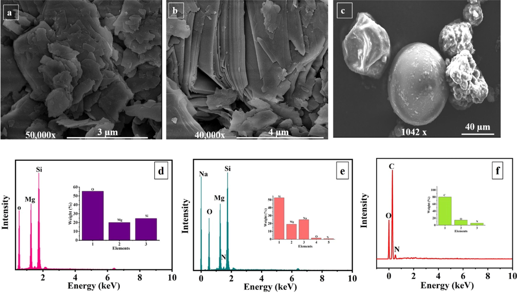
FE-SEM and EDS analysis, of (a, d) as-received TNPs, (b, e) TNPs loaded with NaNO3 and (c, f) encapsulated UFMCs.
The isotherm of the Brunauer-Emmett-Teller (BET) showing the specific surface areas of the as-received TNPs and loaded TNPs are presented in Fig. 2, with an inset showing cumulative pore volume. The specific surface area (SSA) of the as-received TNPs is determined to be 33.41 m2g−1, and the cumulative pore volume is computed to be 0.18 ccg−1 (Qin et al., 2020, 2018). The BET measurements of the loaded TNPs indicate that the SSA is decreased to be 29.37 m2g−1. In addition, the pore volume is also reduced to 0.16 ccg−1, revealing the loading of the inhibitor (NaNO3) into TNPs.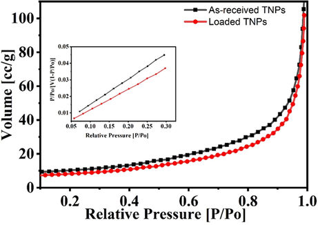
BET analysis of as-received TNPs and loaded TNPs.
The structural and chemical interaction of species present in the as-received TNPs, the loaded TNPs, and the UFMCs encapsulated with linseed oil were investigated through FTIR. For a clear comparison, the FTIR spectra of NaNO3, the as-received TNPs, and the loaded TNPs are presented in Fig. 3. A detailed discussion about FTIR analysis of the UFMCs encapsulated with linseed oil can be found in our previous published work (Habib et al., 2019). As shown in Fig. 3 (inset), in the case of as-received TNPs, the absorbance peak at 1059 cm−1 is assigned to a different vibration, and bending modes of Si-O-Si, Si-O, and O-Si-O tetrahedral layer (Marzbani et al., 2016; Shchukina et al., 2018; Szabó et al., 2015b) and the peaks at 667 and 3659 cm−1 are related to the MgO/MgOH octahedral layer (Marzbani et al., 2016). There are no significant changes in the intensity of the peaks upon the loading of NaNO3 into TNPs. Though some shift in wavenumbers of the absorption band is seen from 1059 to 1070 and 3659 to 3673 cm−1, indicating changes in vibrations of talc lattice (Bahrani et al., 2018). However, additional peaks of NaNO3 provide interaction between TNPs and the inhibitor. It can be noticed from the inset of Fig. 3, the characteristic peaks of NaNO3 are observed at 1328 and 2426 cm−1 due to N-O symmetric and asymmetric stretching vibrations, which are shifted to 1353 and 2431 cm−1 in the loaded TNPs (Trivedi and Dahryn Trivedi, 2015). This displacement in the peaks after loading can be ascribed to the physisorption and electrostatic interaction taken place between TNPs and the inhibitor (Ubaid et al., 2019b).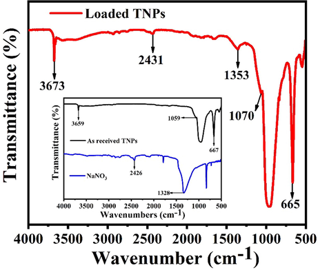
FTIR spectra of as-received TNPs and loaded TNPs.
The XRD spectra of the as-received TNPs and the loaded TNPs are shown in Fig. 4. It can be seen that the spectra of the as-received TNPs demonstrate a crystalline behavior with characteristic basal diffraction peaks at 9.5°, 18.9°, 19.3° and 28.7° corresponding to (0 0 1), (0 0 2), (0 2 0) and (0 3 0) crystal planes, respectively (Marzbani et al., 2016). It can be further noticed that the original crystalline crystal structure of TNPs is preserved even after the loading of NaNO3. However, some new diffraction peaks of NaNO3 at 29.6° and 39.1° corresponding to the crystal planes of (1 1 0) and (0 0 2) have appeared, revealing that NaNO3 has been loaded in TNPs. A detailed discussion of the XRD spectrum of UFMCs encapsulated with linseed oil can be found in our previous publication (Habib et al., 2019).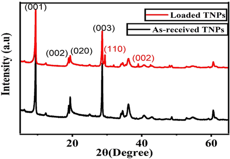
XRD patterns of as-received TNPs and loaded TNPs.
3.2 Thermal stability of developed smart containers
The TGA and DTA curves of the as-received TNPs and the loaded TNPs are shown in Fig. 5. In the case of the as-received TNPs (Fig. 5 (inset)), there is no noticeable weight loss to 850 °C. This excellent thermal stability of the as-received TNPs can be attributed to their inherent high decomposition temperature (1500 °C). Only ∼ 0.1% weight loss is observed until the entire heating window, which may be associated with the adsorbed moisture. In contrast, in the TGA curve of the loaded TNPs, there is a considerable amount of weight loss. The weight loss can be seen in four stages, as shown in Fig. 5. Initially, stage 1, the loaded TNPs, remains quite stable up to 335 °C. During stage 2, the loaded TNPs starts to decrease its weight slowly due to the decomposition of NaNO3 as it is unstable after 350 °C which is due to the decomposition of sodium nitrate into sodium nitrite (NaNO2) (Habib et al., 2019). In stage 3, a further small amount of weight loss is observed. When the temperature is further increased up to 850 °C designated as stage 4, it is observed that almost all the NaNO3 has been decomposed into sodium oxide, nitrogen dioxide and oxygen. A sharp endothermic peak is observed at 600 °C, showing decomposition of the loaded TNPs, and ∼ 10% of weight loss is observed at this stage following the DTA curve. At 650 °C, the exothermic peak and the positive loop are found, which may be related to the thermal oxidation process (Navio et al., 1992). The thermal stability of UFMCs/LO is already being reported in our previous publication (Habib et al., 2019).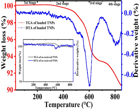
TGA and DTA analysis of as-received TNPs and loaded TNPs.
Based on weight loss measurements observed in TGA, we can calculate the amount of the inhibitor that is loaded into TNPs by following Equation 1 (Mekeridis et al., 2011). The weight of the loaded TNPs at the initial stage (321 °C) is considered as W1; the weight of the loaded TNPs at the 4th stage (850 °C) is taken as W2 and the difference in the weight loss is ΔW = W2-W1. Hence, the ratio mass loss (rm) for the loaded TNPs is 10% w/w following Equation 1.
3.3 Structural and thermal characteristics of developed nanocomposites coatings
FTIR spectra of the developed polymeric nanocomposites coatings and the blank epoxy coatings are shown in Fig. 6. All FTIR spectra have common peaks at 823, 1036, 1457, 1505, and 2925 cm−1. The peak at 823 cm−1 is assigned to the oxirane C-O-C stretching, which may be due to the cross-linking between the epoxy and the hardener. The peak at 1036 is designated to the stretching of C-O-C of an ether. The peaks at 1457 and 1505 cm−1 are related to the deformation of the C-H of CH2 and CH3, and 2925 cm−1 is assigned to the stretching of the aromatic ring (González et al., 2012). The absence of any additional peaks in all FTIR spectra proves that there is no unwanted reaction taking place between the epoxy and the smart containers (loaded TNPs and encapsulated UFMCs). Thus, the incorporation of the loaded TNPs and the encapsulated UFMCs into the epoxy matrix will not lead to a degradation in the properties of the polymeric nanocomposites. These results are also in accordance with the previously published reports (Feng and Cheng, 2017).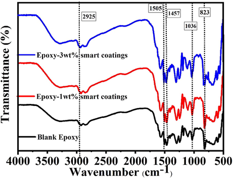
FTIR analysis of the smart polymeric nanocomposite coatings and the blank epoxy.
A comparison of the thermal stability of the polymeric nanocomposites and the blank epoxy coatings is presented in Fig. 7. The weight loss measurements indicate that all synthesized nanocomposites and the blank epoxy coatings do not show any noticeable degradation up to 350 °C, and only ∼6% weight loss is noticed. The major degradation can be noticed after 350 °C contributing to ∼80–85% weight loss. This reduction in the weight loss can be attributed to the (i) degradation of the long epoxy chains and bonds and (ii) Decomposition of NaNO3. The weight loss after 400 °C can be ascribed to the removal of some additives present in the epoxy matrix (Ubaid et al., 2019a). The TGA analysis indicates that the polymeric nanocomposites are thermally stable up to 350 °C, and the incorporation of the loaded TNPs and the encapsulated UFMCs has not hampered the inherent decent thermal characteristics of the epoxy matrix making them attractive for many industrial applications.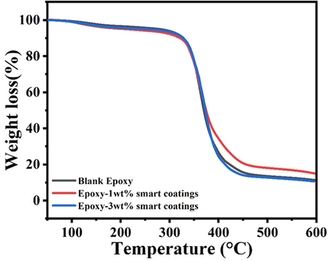
A comparison of TGA curves of polymeric nanocomposite coatings and blank epoxy.
3.4 Self-healing characteristics of polymeric nanocomposites coatings
The self-healing ability of the developed polymeric nanocomposites was investigated through a field emission scanning electron microscope (FE-SEM) over a period of 96 h. The FE-SEM results for the smart polymeric coatings containing 3 wt% loaded TNPs are presented in Fig. 8a. The results of 1 wt% are not reported to avoid the repetition of the results as a similar trend is observed. It can be observed that the initial scratch width is ∼160 μm at 0 h, and the scratch width decreases with time. After 96 h, the scratch is almost healed up, indicating decent self-healing performance. This healing effect can be attributed to the fact that when the scratch is made, the microcapsules are broken down upon mechanical stress and released linseed oil to form a protective layer on the damaged area. Linseed oil upon interaction with air or oxygen starts to polymerize and auto-oxidies, which leads to cross-linking, and eventually, the formation of a protective layer on the exposed steel substrate (Lang and Zhou, 2017). Moreover, the localized change in the pH triggered the release of the inhibitor from TNPs, which contributes to the inhibition of the corrosion effect on the scratched area. These findings are also consistent with previous studies (Habib et al., 2019; Habib et al., 2021).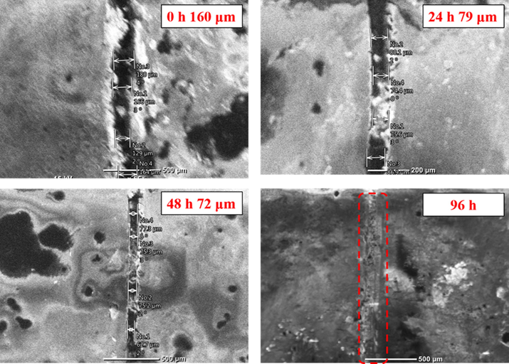
. FE-SEM analysis of the polymeric nanocomposite coatings containing 3 wt% loaded TNPs at different intervals of time (0, 24, 48, 96 h).
In order to confirm the release of the linseed oil to form a protective layer and NaNO3 to inhibit corrosion on the scratched area, the EDS analysis of the polymeric nanocomposites coatings containing 3 wt% TNPs and UFMCs/LO after immersion in 3.5 wt% NaCl solution for 96 h was carried out, as shown in Fig. 8b. The inset in Fig. 8b shows the weight percentages of the detected elements. It can be seen that characteristic peaks of carbon (C), oxygen (O), representative of linseed, and nitrogen (N), associated with NaNO3, are detected, confirming the release of the self-healing agent from the UFMCs and the inhibitor from TNPs.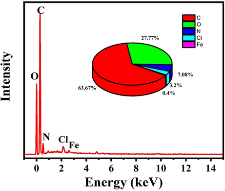
. EDS analysis of the protective film formed on the scratched area of the polymeric nanocomposite coatings containing 3 wt% TNPs.
3.5 The corrosion inhibition efficiency of polymeric nanocomposites
EIS was employed, at open circuit potential, to study the protective efficiency of the scratched blank epoxy and the scratched developed polymeric nanocomposites coatings containing 1 and 3 wt% TNPs and UFMCs/LO applied on the polished steel substrates and immersed in 3.5 wt% NaCl solution at room temperature. The immersion times were 24, 48, 72, 96, and 120 h. The Bode, phase angle, and Nyquist plots for the blank epoxy coatings are shown in Fig. 9 (a, b, and S3a, respectively). Commonly, in the bode plots, the higher values of impedance at low frequency |Z0.1Hz| is often associated with the protective behavior of the coatings. It was observed from Fig. 9a that, after 24 h of immersion, the impedance value at low frequency |Z0.1Hz| was the highest compared to those of the rest of the immersion times. As immersion time is increasing, the impedance value of the blank epoxy is depreciating, elucidating the decrease in its protective ability. In the Nyquist plots, as the Nyquist semicircle diameter is increased, the protective behavior of the coatings is increased. Thus, the same behavior can be seen in both the Nyquist plot in Figure S3a and the corresponding bode plots (Fig. 9a). The Zreal showed a decrease with the passing of immersion time, which is an indication of the decrease in the overall protection provided by the blank epoxy coatings. In the phase angle plot (Fig. 9b), two capacitance loops have been observed. These loops decreased, at high and low frequency, with the passing of immersion times indicating the decrease in the corrosion resistance of the blank epoxy (Wang et al., 2019). The shift in the phase angle plots towards the less negative value is consistent with the corresponding Bode plots. The relationship between the impedance modulus and the capacitance loop is direct. The lower the impedance modulus, the lower the capacitance loop, and vice versa.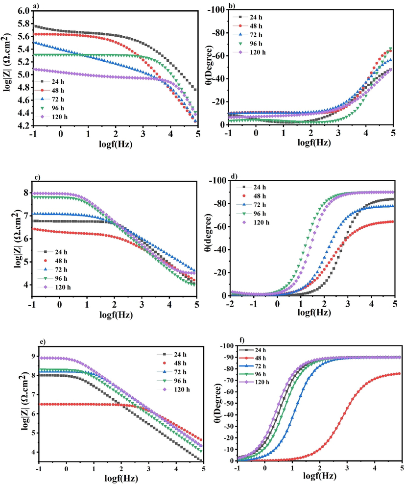
a) Bode, b) Phase angle for the blank epoxy matrix, c) Bode, d) Phase angle for the polymeric nanocomposite coatings containing 1 wt% TNPs, e) Bode, f) Phase angle for the polymeric nanocomposite coatings containing 3 wt% TNPs.
Fig. 9 (c, d) and (e, f), respectively, showed the Bode and phase angle plots for the scratched polymeric nanocomposite coatings containing 1 and 3 wt% TNPs and UFMCs/LO at different immersion times. Their Nyquist plots showed in Figure S3 (b and c), respectively. The low-frequency impedance values (|Z0.1Hz|) in the Bode plots (Fig. 9c and 9e) and the Nyquist semicircles shown in Figures S3b and S3c for the two nanocomposites coatings revealed a decreasing trend the same as the corresponding ones of the blank epoxy coating after 24 h immersion time. This is due to the diffusion of the electrolyte into the substrate and the formation of the corrosion products at the defect site. At that stage, the steel substrate at the scratched site interacts with the Cl- ion in the solution that leads to the formation of the conductive paths and enhances the corrosion rate (Attaei et al., 2020b). After 48 h and further increase in the immersion time, we can observe a different trend compared to the corresponding blank epoxy. An increase in the low-frequency impedance values and in the Nyquist semicircle plots is seen for both nanocomposite coatings, as shown in Fig. 9 (c and S3b) (e and S3c), respectively. This demonstrates the imperative recovery of the protective barrier properties of the nanocomposite coatings and emphasizes the release of the self-healing agent and the corrosion inhibitor in the scratched area, as previously explained in section 3.5. The self-healing agent polymerized to form a protective layer on the scratched area, and the corrosion inhibitor (NaNO3) is released from the TNPs, which further inhibits the corrosion onset. Furthermore, the phase angle values of the polymeric nanocomposite coatings (1 and 3 wt% TNPs and UFMCs/LO) after 120 h of immersion are close to −85° and −90°, as shown in Fig. 9 d and 9f, respectively, illustrating their capacitance behavior.
The evolution of values of Rct, Rpo, CPE1 and CPE2 of the blank epoxy and the modified polymeric nanocomposite coatings are represented in Fig. 10 (a, b, c and d) respectively. The obtained fitting parameters are shown in Table S1. The impedance data of the blank epoxy and the developed polymeric nanocomposite coatings are fitted using the electrical equivalent circuits shown in Fig. 11a and b, respectively. The circuits utilized for fitting the EIS data for all coatings are two-time constants. The resistances presented in the equivalent circuits are designated as Rs for the solution resistance, Rpo for the pore resistance and Rct for the charge transfer resistance. The CPE1 and CPE2 are constant phase elements that associated with the coating and the electrical double layer at the metal/coating interface, respectively. Due to the non-homogeneity of all coatings, they are employed instead of coating capacitance (Cc) and double layer capacitance (Cdl), respectively. Additionally, a Warburg diffusion element (W) was included to express the mass transfer at the low-frequency domain. The time constant at low frequency (Rct/CPE2) is associated with the barrier properties of the polymeric nanocomposite coatings at the interface between the metal and the coating, whereas the time constant at high frequency (Rpo/CPE1) is related to the polymeric composite properties. The impedance of CPE is calculated using the following Equation (Abdelaal et al., 2018; Hsu and Mansfeld, 2001);
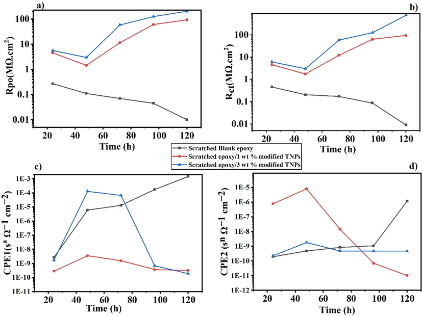
Evolution of the (a) coating pore resistance Rpo, (b) charge transfer resistance of the coatings Rct (c) value of the capacitance CPE1, (d) value of the capacitance CPE2.
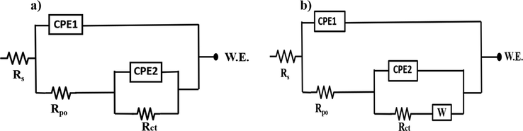
Equivalent circuit used to fit data a) Blank epoxy coatings b) polymeric nanocomposite coatings.
In the case of the blank epoxy, as presented in Fig. 10b and Table S1, after 24 h of immersion, the noted Rct value is 0.46 MΩ.cm2, having a maximum semicircle in the Nyquist plot. After 120 h of immersion, there is an expectation for a substantial decrease in the value of Rct that is 0.01 MΩ.cm2, suggesting that the blank epoxy starts to corrode and lose its protective ability. This is also an indication that the blank epoxy is not providing any further protection at the scratched area because there is nothing preventing the flow of the electrolyte. Furthermore, the Rpo values decreased from 0.27 MΩ cm2 to 0.01 MΩ cm2 after 120 h immersion time, as shown in Fig. 10a. Besides, the increase in the value of CPE1 and CPE2 with immersion time, as illustrated in Fig. 10 (c and d, respectively), shows the deterioration of the protective coating.
In case of the polymeric nanocomposite coatings containing 1 wt% TNPs and UFMCs/LO, it is noticed that the Rct value is 4.61 MΩ cm2 after 24 h of immersion, as shown in Fig. 10b and Table S1. This value is decreased to 1.75 MΩ cm2 after 48 h that may be accounted to the presence of some pores from the insufficient release of the self-healing agent, which encouraged the onset of corrosion on the scratched area. As immersion time is increased, the Rct value starts to increase, reaching 93.63 MΩ cm2 after 120 h of immersion (Fig. 10b). This indicates the complete release of the self-healing agent in addition to the release of the inhibitor from the TNPs. Since the immersion time is increased, the local pH of the media is changed resulting in the triggering of the inhibitor’s release. Therefore, the increase in the Rct values with immersion time is an indication that the addition of TNPs nanocomposites is providing good corrosion protection. Moreover, the polymeric nanocomposites coatings containing 3 wt% TNPs and UFMCs/LO showed the same behavior with approximately 8 times higher Rct values, along the immersion times, compared to the corresponding polymeric nanocomposites containing 1 wt% TNPs, as shown in Fig. 10b and Table S1. The lessened Rct value of the polymeric nanocomposite coatings containing 1 wt% TNPs is due to the smaller concentration of TNPs. Although the concentration of the self-healing agent is the same (5 wt%) in both the polymeric nanocomposites, the corrosion inhibitor did have a contribution in inhibiting corrosion. Furthermore, it is worthy to be mentioned that the inhibitor’s release is accompanied with a diffusion process, which can be notified as (W) in Fig. 11b. Since the inhibitor is joined in the electrochemical reaction of the corrosion mechanism, as described later in section 3.6, and formed a protective layer along with the self-healing agent. Thus, the diffusion process of the inhibitor' release has a considerable effect on retarding the Cl- ions penetrating through the coating. This can be clearly observed from the consistently increased values of the Warburg diffusion coefficient (W) with the charge transfer resistances values (Rct) of the polymeric coatings, as shown in Table S1.
Moreover, the Rpo values showed the same trend as the Rct value, where it was 4.54 MΩ cm2 and 5.61 MΩ cm2 after 24 h and increased to 93.45 MΩ cm2 and 204.8 MΩ cm2 for the polymeric nanocomposite coatings containing 1 wt% and 3 wt% TNPs, respectively, as represented in Fig. 10a. The decrease in CPE1 and CPE2 with immersion time (Fig. 10 c and d) for both composition of polymeric nanocomposites is further proof that the developed nanocomposite coatings are providing enough protection. The increase in the resistance values with the immersion time is related to the good compatibility of the TNPs and the microcapsules with the epoxy matrix and an indication that the release of the inhibitor and the self-healing agent is a time-dependent process. It worth mention that the corrosion inhibition efficiency (IE) of the developed polymeric nanocomposites is calculated by the following equation (Shahzad et al., 2020);
3.6 Self-healing and corrosion inhibition mechanism of polymeric nanocomposites
The corrosion inhibition mechanism of the inhibitor (NaNO3) is mainly associated with its capability to easily reduce to nitrite by a ferrous ion as represented in equation 6. The most important reaction in the corrosion process initiated due to interaction of steel with Cl-, which leads to the formation of Fe2+, can be described by Equation 4 (Ryu et al., 2017);
The Fe2+ are soluble and can be easily transported to the defect site in the presence of chloride ions and proceed the corrosion process, but due to the presence of NaNO3 it will interact with nitrate ions to convert Fe2+ to Fe3+ to form a ferric oxide layer on the steel substrate. Nitrite is then reduced to nitric oxide. Though nitric oxide gas is very toxic but at ambient temperature and pressure, it usually evaporates, as shown in Equation 6 (Gaidis, 2004).
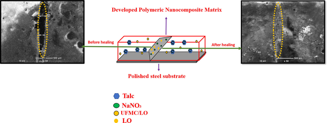
The detailed healing mechanism is explained in the schematic diagram shown in Fig. 12. Upon mechanical damage, i-e scratch, the encapsulated UFMCs incorporated into the polymeric matrix, break instantaneously to release linseed oil (healing agent), and transport it to defect site. Due to the rough outside surface of UFMCs, as shown in Fig. 1c, it will have good adhesion with polymer matrix, which will release the linseed oil due to mechanical stress (Suryanarayana et al., 2008). Linseed oil consists of unsaturated fatty acid with long chains of carbon–carbon double bond (C=C). When linseed oil is released from microcapsules, it oxidizes due to interaction with oxygen or air and then forms a passive layer on the damaged/scratched part due to the oxidation of C=C (Habib et al., 2019). Since linseed oil is cured easily while interaction with air, it forms a protective layer to heal the damage. Moreover, the formation of scratch initiated the corrosion process due to that the local pH of the defect site will also change, which in turn triggers the release of corrosion inhibitor from TNPs. The efficient corrosion inhibition efficiency is also evident through EIS analysis and is accredited by two factors that are self-healing functionality delivered by linseed oil and corrosion inhibition performance offered by corrosion inhibitor.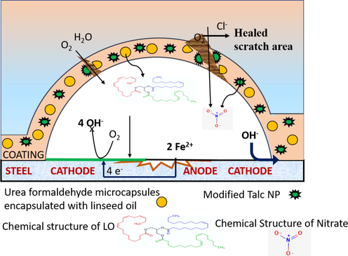
Schematic diagram showing the self-healing and corrosion inhibition mechanism of the developed polymeric nanocomposite coatings.
4 Conclusion
Polymeric nanocomposite coatings were developed by reinforcing the epoxy matrix with varying amounts of TNPS (1 wt% and 3 wt%) loaded with NaNO3 at a fixed concentration of UFMCs encapsulated with linseed oil (5 wt%). A comparison of the structural, thermal, self-healing, and corrosion inhibition properties was conducted to elucidate the salient characteristics of the developed polymeric nanocomposites. Promising self-healing properties and tempting corrosion inhibition efficiency of 99.9% and 99.5%, associated with polymeric nanocomposites containing 3 wt% and 1 wt% loaded TNPs, respectively, are achieved. The promising characteristics of polymeric nanocomposite coatings can be attributed to the careful selection of compatible nanocontainers, inhibitor, and self-healing agents. The improved properties of polymeric nanocomposites make them attractive for many industrial applications.
Funding
This research was funded by Qatar National Research Fund (a member of the Qatar Foundation), grant number NPRP Grant 11S–1226–170132. Statements made herein are solely the responsibility of the authors.
Acknowledgement
The authors would like to thank the Central laboratory Unit (CLU), Qatar University, 2713, Doha, Qatar, for SEM analysis facility.
Data availability
The raw/processed data required to reproduce these findings cannot be shared at this time due to legal or ethical reasons.
Declaration of Competing Interest
The authors declare that they have no known competing financial interests or personal relationships that could have appeared to influence the work reported in this paper.
References
- N-aminophthalimide as a synthon for heterocyclic schiff bases: efficient utilization as corrosion inhibitors of mild steel in 0.5 mol.L-1 H2SO4 solution. Egypt. J. Chem.. 2018;61:539-558.
- [CrossRef] [Google Scholar]
- Clay nanotubes for corrosion inhibitor encapsulation: release control with end stoppers. J. Mater. Chem.. 2010;20(32):6681.
- [CrossRef] [Google Scholar]
- Smart epoxy coating modified with isophorone diisocyanate microcapsules and cerium organophosphate for multilevel corrosion protection of carbon steel. Prog. Org. Coat.. 2020;147:105864.
- [CrossRef] [Google Scholar]
- Autonomous self-healing in epoxy coatings provided by high efficiency isophorone diisocyanate (IPDI) microcapsules for protection of carbon steel. Prog. Org. Coat.. 2020;139:105445.
- [CrossRef] [Google Scholar]
- Chemical modification of talc with corrosion inhibitors to enhance the corrosion protective properties of epoxy-ester coating. Prog. Org. Coat.. 2018;120:110-122.
- [CrossRef] [Google Scholar]
- Influence of Embedded Nanocontainers on the Efficiency of Active Anticorrosive Coatings for Aluminum Alloys Part I: Influence of Nanocontainer Concentration. ACS Appl. Mater. Interfaces. 2012;4(6):2931-2939.
- [CrossRef] [Google Scholar]
- In situ poly(urea-formaldehyde) microencapsulation of dicyclopentadiene. J. Microencapsul.. 2003;20(6):719-730.
- [CrossRef] [Google Scholar]
- Hollow mesoporous zirconia nanocontainers for storing and controlled releasing of corrosion inhibitors. Ceram. Int.. 2014;40(7):10457-10463.
- [CrossRef] [Google Scholar]
- An intelligent coating doped with inhibitor-encapsulated nanocontainers for corrosion protection of pipeline steel. Chem. Eng. J.. 2017;315:537-551.
- [CrossRef] [Google Scholar]
- Chemistry of corrosion inhibitors. Cem. Concr. Compos.. 2004;26(3):181-189.
- [CrossRef] [Google Scholar]
- Applications of FTIR on Epoxy Resins - Identification, Monitoring the Curing Process, Phase Separation and Water Uptake. Infrared Spectrosc. - Mater. Sci. Eng. Technol. 2012;2
- [CrossRef] [Google Scholar]
- Habib, S., Fayyad, E., Nawaz, M., Khan, A., Shakoor, R.A., 2020. Cerium Dioxide Nanoparticles as Smart Carriers for Self-Healing Coatings. https://doi.org/10.3390/nano10040791
- Improved self-healing performance of polymeric nanocomposites reinforced with talc nanoparticles (TNPs) and urea-formaldehyde microcapsules (UFMCs) Arabian J. Chem.. 2021;14(2):102926.
- [CrossRef] [Google Scholar]
- Habib, S., Khan, A., Nawaz, M., Sliem, M.H., Shakoor, R.A., Kahraman, R., Abdullah, A.M., Zekri, A., 2019. Self-healing performance of multifunctional polymeric smart coatings. Polymers (Basel). 11. https://doi.org/10.3390/polym11091519
- Technical Note: Concerning the Conversion of the Constant Phase Element Parameter Y0 into a Capacitance. CORROSION. 2001;57:747-748.
- [CrossRef] [Google Scholar]
- Hybrid halloysite nanotubes as smart carriers for corrosion protection. ACS Appl. Mater. Interfaces. 2020;12(33):37571-37584.
- [CrossRef] [Google Scholar]
- Designing and performance evaluation of polyelectrolyte multilayered composite smart coatings. Prog. Org. Coat.. 2019;137:105319.
- [CrossRef] [Google Scholar]
- Synthesis and properties of polyelectrolyte multilayered microcapsules reinforced smart coatings. J Mater Sci. 2019;54(18):12079-12094.
- [CrossRef] [Google Scholar]
- Synthesis and characterization of poly(urea-formaldehyde) microcapsules containing linseed oil for self-healing coating development. Prog. Org. Coat.. 2017;105:99-110.
- [CrossRef] [Google Scholar]
- Lvovich, V.F., 2012. Impedance Spectroscopy: Applications to Electrochemical and Dielectric Phenomena, Impedance Spectroscopy: Applications to Electrochemical and Dielectric Phenomena. https://doi.org/10.1002/9781118164075
- Marzbani, P., Resalati, H., Ghasemian, A., Shakeri, A., 2016. Surface Modification of Talc Particles with Phthalimide: Study of Composite Structure and Consequences on Physical, Mechanical, and Optical Properties of Deinked Pulp. BioResources 11. https://doi.org/10.15376/biores.11.4.8720-8738.
- Release studies of corrosion inhibitors from cerium titanium oxide nanocontainers. J. Nanopart Res.. 2011;13(2):541-554.
- [CrossRef] [Google Scholar]
- Analytical characterization of silane films modified with cerium activated nanoparticles and its relation with the corrosion protection of galvanised steel substrates. Prog. Org. Coat.. 2008;63(3):330-337.
- [CrossRef] [Google Scholar]
- Chemical composition and corrosion protection of silane films modified with CeO2 nanoparticles. Electrochim. Acta. 2009;54(22):5179-5189.
- [CrossRef] [Google Scholar]
- Nahir, T.M., 2005. Impedance Spectroscopy: Theory, Experiment, and Applications, 2nd ed Edited by Evgenij Barsoukov (Texas Instruments Inc.) and J. Ross Macdonald (University of North Carolina, Chapel Hill). John Wiley & Sons, Inc.: Hoboken, NJ. 2005. xvii + 596 pp. $125. J. Am. Chem. Soc. https://doi.org/10.1021/ja059742o.
- Biobased self-healing polyurethane coating with Zn micro-flakes for corrosion protection of AA7475. Chem. Eng. J.. 2021;404:126478.
- [CrossRef] [Google Scholar]
- Self-healing ability based on hydrogen bonds in organic coatings for corrosion protection of AA1200. Corros. Sci.. 2020;177:108984.
- [CrossRef] [Google Scholar]
- Novel healing coatings based on natural-derived polyurethane modified with tannins for corrosion protection of AA2024-T3. Corros. Sci.. 2020;162:108213.
- [CrossRef] [Google Scholar]
- Thermal decomposition of sodium nitrite and sodium nitrate pre-adsorbed on TiO2 surfaces. J. Therm. Anal.. 1992;38:673-682.
- [CrossRef] [Google Scholar]
- Nawaz, M., Habib, S., Khan, A., Shakoor, R.A., Kahraman, R., 2020a. autonomous self-healing in epoxy coatings. https://doi.org/10.1039/c9nj06436b.
- Nawaz, M., Habib, S., Khan, A., Shakoor, R.A., Kahraman, R., 2020b. Cellulose microfibers (CMFs) as a smart carrier for autonomous self-healing in epoxy coatings. New J. Chem. https://doi.org/10.1039/C9NJ06436B.
- Orazem, M.E., Tribollet, B., 2008. Electrochemical impedance spectroscopy.
- Dual-action smart coatings with a self-healing superhydrophobic surface and anti-corrosion properties. J. Mater. Chem. A. 2017;5:2355-2364.
- [CrossRef] [Google Scholar]
- Fabrication and electromagnetic performance of talc/NiTiO3 composite. R. Soc. Open Sci.. 2020;5:171083.
- [CrossRef] [Google Scholar]
- Qin, W., Xia, T., Ye, Y., Zhang, P., 2018. Subject Category : Subject Areas : Fabrication and electromagnetic performance of talc / NiTiO 3 composite.
- An electrochemical study to evaluate the effect of calcium nitrite inhibitor to mitigate the corrosion of reinforcement in sodium chloride contaminated Ca(OH)2 solution. Adv. Mater. Sci. Eng.. 2017;2017
- [CrossRef] [Google Scholar]
- Halloysites and mesoporous silica as inhibitor nanocontainers for feedback active powder coatings. Prog. Org. Coatings. 2018;123:384-389.
- [CrossRef] [Google Scholar]
- Photocatalytically-active and photocontrollable coatings based on titania-loaded hybrid sol–gel films. J. Mater. Chem.. 2009;19:4931-4937.
- [CrossRef] [Google Scholar]
- “SMART” protective ability of water based epoxy coatings loaded with CaCO3 microbeads impregnated with corrosion inhibitors applied on AA2024 substrates. Electrochim. Acta. 2012;83:439-447.
- [CrossRef] [Google Scholar]
- Hydroxyapatite microparticles as feedback-active reservoirs of corrosion inhibitors. ACS Appl. Mater. Interfaces. 2010;2:3011-3022.
- [CrossRef] [Google Scholar]
- Suryanarayana, C., Rao, K.C., Kumar, D., 2008. Progress in Organic Coatings Preparation and characterization of microcapsules containing linseed oil and its use in self-healing coatings 63, 72–78. https://doi.org/10.1016/j.porgcoat.2008.04.008.
- Linseed oil-filled microcapsules containing drier and corrosion inhibitor - Their effects on self-healing capability of paints. Prog. Org. Coatings. 2015;84:136-142.
- [CrossRef] [Google Scholar]
- Linseed oil-filled microcapsules containing drier and corrosion inhibitor – their effects on self-healing capability of paints. Prog. Org. Coatings. 2015;84:136-142.
- [CrossRef] [Google Scholar]
- The combined use of scanning vibrating electrode technique and micro-potentiometry to assess the self-repair processes in defects on “smart” coatings applied to galvanized steel. Electrochim. Acta. 2011;56:4475-4488.
- [CrossRef] [Google Scholar]
- Zn–Al layered double hydroxides as chloride nanotraps in active protective coatings. Corros. Sci.. 2012;55:1-4.
- [CrossRef] [Google Scholar]
- Self-healing polymer nanocomposite materials: a review. Polymer (Guildf).. 2015;69:369-383.
- [CrossRef] [Google Scholar]
- Spectroscopic characterization of disodium hydrogen orthophosphate and sodium nitrate after biofield treatment. J. Chromatogr. Sep. Tech.. 2015;06
- [CrossRef] [Google Scholar]
- Effect of concentration of DOC loaded TiO 2 nanotubes on the corrosion behavior of smart coatings. Ceram. Int.. 2019;45:10492-10500.
- [CrossRef] [Google Scholar]
- Multifunctional self-healing polymeric nanocomposite coatings for corrosion inhibition of steel. Surf. Coatings Technol.. 2019;372:121-133.
- [CrossRef] [Google Scholar]
- Vijayan P., P., Al-Maadeed, M.A.S.A., 2016. TiO2 nanotubes and mesoporous silica as containers in self-healing epoxy coatings. Sci. Rep. 6, 38812. https://doi.org/10.1038/srep38812.
- Vijayan P.P., Hany El-Gawady, Y.M., Al-Maadeed, M.A.S.A., 2016. Halloysite Nanotube as Multifunctional Component in Epoxy Protective Coating. Ind. Eng. Chem. Res. 55, 11186–11192. https://doi.org/10.1021/acs.iecr.6b02736.
- Self-healing performance and corrosion resistance of graphene oxide–mesoporous silicon layer–nanosphere structure coating under marine alternating hydrostatic pressure. Chem. Eng. J.. 2019;361:792-804.
- [CrossRef] [Google Scholar]
- Halloysite nanotubes as nanocontainer for smart coating application: A review. Prog. Org. Coatings. 2017;111:175-185.
- [CrossRef] [Google Scholar]
Appendix A
Supplementary material
Supplementary data to this article can be found online at https://doi.org/10.1016/j.arabjc.2020.102926.
Appendix A
Supplementary material
The following are the Supplementary data to this article:


