

Translate this page into:
Influence of pH values on the electrochemical performance of low carbon steel coated by plasma thin SiOxCy films
⁎Corresponding author at: Department of Chemistry, Faculty of Science (Men’s Campus), Al-Azhar University, Nasr City, 11884 Cairo, Egypt. alaa.fahmy@azhar.edu.eg (Alaa Fahmy)
-
Received: ,
Accepted: ,
This article was originally published by Elsevier and was migrated to Scientific Scholar after the change of Publisher.
Abstract
Chromium (VI) coatings are highly toxic and carcinogenic; therefore, thea should be replaced by a new eco-friendly material that retains its effectiveness in terms of corrosion. Herein, thin silicon oxycarbide films as an eco-friendly anticorrosive coating were deposited on a low carbon steel substrate by a radio frequency capacitively coupled plasma technique using tetraethyl orthosilicate (TEOS) as a precursor. The corrosion performance of the coatings were evaluated by potentiodynamic polarization and electrochemical impedance spectroscopy (EIS) in dependence on the gap distance between the plasma electrodes and the pH values at room temperature. The chemical bonding and morphological features of the deposited films were investigated by Fourier Transformer Infrared Spectroscopy in Attenuated Total Reflectance (ATR-FTIR) mode, X-Ray Diffraction (XRD), and energy-dispersive X-ray spectroscopy (EDX) coupled with scanning electron microscopy (SEM). The values were significantly decreased by reducing the gap distance and reached a minimum at 1 cm gap distance. It was reduced from 12 µA/cm2 for the blank sample to 0.714 µA/cm2 in treated sample at gap distance 1 cm and protective efficiency reached ∼ 94% in the neutral solution. Nevertheless, the best protective efficiency achieved more than 99% of the total protection in alkaline medium as measured at room temperature for treated sample at gap distance 1 cm.
Keywords
Corrosion resistance
Mild steel
Plasma treatments
Tetraethyl orthosilicate
Thin film

1 Introduction
Low-carbon steel is the most widely applied form of carbon steel, containing a carbon content of less than 0.25 wt%. Therefore, it has a remarkable economic and industrial importance due to its reasonable cost and excellent mechanical properties. It is often employed in structural shapes (angle iron and channel), automobile, bridge and construction components, food cans, and pipes (Naderi and Sarhan, 2019). Corrosion poses a serious problem for these metallic materials, due to most metals including carbon steel, not being thermodynamically stable. Therefore, they become corroded especially in atmospheric and aqueous mediums (Rangel et al., 2019). The corrosion process destroys millions of tons of carbon steel per year (Shekari et al., 2017; Kusmanov et al., 2016). Moreover, almost 3% of the total global native product (∼2.8 trillion US dollars) is wasted every year due to corrosion-related issues (Rangel et al., 2020). Thus, it is important to improve the corrosion resistance of carbon steel without losing its physical and mechanical properties.
Chromate coating was used to advance the resistivity of corrosion for a long time due to its simplicity (Sakai et al., 2012). It is normally produced by either electrochemical or chemical treatments of carbon steel in a solution including hexavalent chromium with other components (Zarras and Stenger-Smith, 2015). In this method the chromate layer is deposited on the substrate surface by dipping rather than a spraying method (Pokorny et al., 2016). Unfortunately, this technique is environmentally harmful (Vassallo et al., 2006; Ponton et al., 2019). Additionally, it has been evidenced that hexavalent chromium species are dispersed by human perspiration (Kendig and Buchheit, 2003). Cr(VI) is highly toxic and carcinogenic and therefore, it should be replaced by a new eco-friendly substitute equally effective in terms of corrosion. Some non-toxic and environmentally friendly coatings techniques have been employed to protect the carbon steel surface. These techniques are either wet such as the sol–gel process (Abuín et al., 2012; Salahinejad et al., 2014; Cheraghi et al., 2012), or dry as chemical vapor deposition (CVD), and plasma-enhanced chemical vapor deposition (PECVD) (Kakiuchi et al., 2012; Ghorbani et al., 2018). Among these techniques, the plasma process is a promising technique for metallic surface modification to enhance its corrosion resistance (Abu-Saied et al., 2019). In contrast to the sol–gel and chemical vapor deposition process, the plasma-enhanced processes are an eco-friendly method and provide high protection efficiency in a short processing time and at a low operating temperature.
Organosilicon precursors are most frequently used for the deposition of thin films on the steel substrate. The deposited films are usually cross-linked, insoluble, pinhole-free, and adhere well to the substrates (Fahmy et al., 2015; Lasorsa et al., 2010; Fahmy et al., 2019). A good homogeneity, high adhesion to a wide range of inorganic and organic surfaces, minimal environmental impact, and competitive cost are the properties of the coatings obtained using the sol–gel coatings technique. Alibakhshi et al. (Alibakhshi et al., 2018) prepared an eco-friendly sol–gel hybrid silane coating based on tetraethylorthosilicate (TEOS) and trimethoxymethylsilane (TMOMS) on a mild steel substrate for corrosion protection. They reported that the hybrid coating with the highest corrosion resistance was obtained by hydrolysis of the mixture of 50% silanes (TEOS/ TMOMS: 50/50 w/w) for 24 h. Nevertheless, the limitation of thickness and presence of defects and micro-cracks in the coating which diminish their protective properties are the main challenges for applying the silane sol–gel system.
Vassallo et al. (Vassallo et al., 2006) discussed the electrochemical properties of steel coated by SiOx-like film in a 1 M Na2SO4 solution. The thin film was fabricated using hexamethyldisiloxane (O2 /HMDSO) plasma fed in a capacitively coupled radio frequency reactor. A homogeneous film with 1.2 µm thickness was obtained at a fed ratio(O2 /HMDSO) = 14 and provided a good corrosion inhibition efficiency. Delimi et al. (Delimi et al., 2010) applied thin films on steel substrate using a mixture of SiH4 (3% in N2) and N2O. They reported that 290 s of plasma treatment is enough to obtain a thin film which decreased the corrosion current (Icorr) of the steel substrate from 7.20 to 0.02 µA/cm−2 in 3% NaCl aqueous solution. Lasorsa et al. (Lasorsa et al., 2010) studied the protective characters of SixOyCz coatings deposited on carbon steel using a two-step process. The protective film was deposited by rf plasma using methyltrimethoxysilane (MTMOS) as a precursor. The deposited coating provides good corrosion resistance against 5% H2SO4 and 0.1 M NaCl solutions at room temperature. Ponton et al. (Ponton et al., 2019) prepared thin and dense SiO2 films with effective electrochemical properties. The film was acquired from tetraethyl orthosilicate (Si(OC2H5)4, TEOS) by chemical vapor deposition (CVD) between 400 and 550 °C. However, a very important step reported in literature for improving the corrosion resistance is the plasma pre-treatment of metal substrates. This has been proved to dramatically improve the corrosion protection ability of the subsequent SiOx layer (Palumbo et al., 2009).
In our previous works (Fahmy et al., 2021; Gangan et al., 2020), protective thin films were prepared by rf plasma using TEOS based on gap distances and plasma power at fixed a deposition time of 10 min. The structure of the deposited films was examined using XPS, FTIR, EDX and XRD and the results confirmed the formation of silicon oxycarbide coating. The electrochemical measurements (in 3.5% NaCl) show an increasing of Rct values for steel substrate from 19.37 to 1485 Ω cm2 at 1 cm gap distance and 100 W of plasma power.
Most of the research in this field is aimed towards the effect of deposited layers against corrosion and how they can be employed as a protective layer with varying conditions such as precursor, time of plasma, power, or the substrate as discussed above. However, little attention is paid to studying the structure − electrochemical relationships of the plasma deposited layer based on the gap distance between the electrodes and the electrochemical performance in different pH mediums.
The article offers an environmentally friendly alternative to replace highly polluting chromium (VI) coatings with SiOxCy coatings. Cr (VI) is highly toxic and carcinogenic as described above and therefore, should be replaced by a new eco-friendly material and that is highly effective against corrosion and does not generate toxic products during its hydrolysis.
Furthermore, the current work aims to prepare a protective silicon oxycarbide coating on the steel substrate using TEOS/Ar plasma and inspect its electrochemical performance in different pH mediums.
2 Experimental
2.1 Materials
Carbon steel samples were obtained from Central Metallurgical Research Institute in Egypt and was analyzed by FOUNDRY-MASTER Optical Emission Spectrometer. The composition of it (in wt%) as follow: 0.271% C, 0.214% Si, 0.829% Mn, 0.0305% P, 0.0156% S, 0.0122% Cr, 0.0187% Ni, 0.0033% Al, 0.0041% Co, 0.0071% Cu, 0.0001% Ti, 0.0028 % V, 0.0095 % W, 0.0095% Pb, 0.0108% As, 0.0003% B and 98.57% Fe. Tetraethyl orthosilicate (TEOS) (Si(OC2H5)4 with molar mass 208 g mol−1 was acquired from Sigma-Aldrich with analytical grade 99%.
2.2 Preparation of SiOx-like thin film
The disc-shaped steel samples (25 mm in diameter and 10 mm in thickness) were polished with silicon carbide emery papers with different grades (60, 80, 120, 400, 800, 1000, and 2000) to get a smooth surface. Afterwards, the samples were washed in acetone and dried at room temperature. As shown in Fig. 1 the electrical electrodes are faced to each other and separated by a distance, this distance is called the gap distance between the two electrodes (interelectrode distance in the plasma reactor).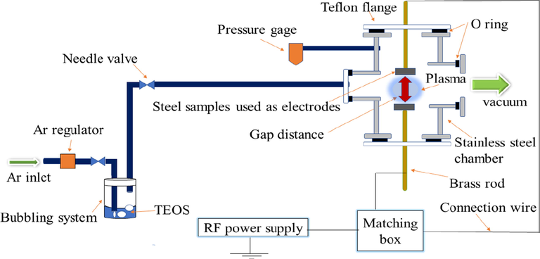
Schematic diagram for the discharge cell.
The steel specimen was then placed in the plasma chamber at room temperature and the chamber was pumped down to 300 mTorr using a vacuum pump. After that, the argon gas was introduced into the bubbler system containing (TEOS) liquid and carried the TEOS vapor into the plasma reactor until the pressure reached 1 Torr. Thereafter, the rf power was switched on and fixed at 100 W for 5 min. SiOx layers were synthesized by the plasma generator (RFG 1 K-13) with 13.6 MHz and 1000 W power. The schematic representation of the experimental setup is shown in Fig. 1.
2.3 Corrosive solutions
The electrochemical measurements of treated steel were carried out in a 3.5% NaCl solution (pH 6.5) at room temperature. Furthermore, the 1 cm gap distance sample (best condition) was evaluated in a wide range of pH values (1.0, 3.0, 5.0, 9.0, and 12.0) to provide a clear understanding of the corrosion behavior of the plasma-treated samples. The solutions with different pH were prepared using a phthalate buffer system as shown in the supplementary (Table S1) (Elsayed et al., 2016).
The analytical grades of the chemicals used were: HCl (37%), NaOH (99.9%), KCl (99.9%), borax (99.9%), NaCl (99.9%), and potassium hydrogen phthalate (99.9%).
2.4 Electrochemical measurements
Electrochemical experiments were carried out with a Potentiostat /Galvanostat /FRA analyzer (Autolab PGSTAT 30), using a classical three-electrode set up with a saturated calomel reference electrode (SCE) and a platinum grid as a counter electrode. The surface area of the working electrode was 1 cm2.
Potentiodynamic polarization tests were performed by scanning an applied potential from −0.3 to 1 mV at a scan rate of 1 mV s−1. The corrosion rate kcorr in (mmpy) was obtained from the Icorr values by the following equation (Fahmy et al., 2021).
The inhibition efficiency (
) was calculated from the potentiodynamic parameter Eq. (2).
Electrochemical impedance spectroscopy (EIS) was done by applying an AC excitation of 10 mV amplitude (peak-to-zero) of sinusoidal voltage in the frequency range from 100 kHz to 10 mHz at open circuit potential (OCP). Impedance data were modeled using ZSim 3.30d software to choose proper electrochemical equivalent circuits and calculate EIS parameters. Also, the inhibition efficiency (
) was calculated using Eq. (3).
2.5 Investigation of the deposited films
2.5.1 Scanning electron microscopy (SEM) and energy-dispersive X-ray spectroscopy (EDX)
The surface morphology was analyzed using SEM (FEI-inspect -S50) with a magnification range up to 100,000 x. The SEM is attached with an EDX unit with an acceleration voltage of 30 kV and used for elemental analysis of the treated sample compared to the untreated ones.
The plasma-treated steel sample was cut into similar halves using a water jet cutter and placed perpendicularly in the SEM unit to take the cross-section shots.
2.5.2 Fourier transformed infrared (FTIR) spectroscopy
The chemical structure of the deposited film was examined using FTIR (Bruker Alpha 2) in attenuated total reflectance ATR mode with a wavenumber range from 400 to 4000 cm−1.
2.5.3 X-ray diffraction (XRD)
The crystalline structure of untreated and treated carbon steel samples was discussed employing X-ray diffraction (XRD, PAN alytical X’Pert pro MPD, PW3040/60 type) in 2θ mode with Cu-Kα radiation (λ = 0.154 nm) at 40 KV and 40 mA.
3 Results and discussion
3.1 Electrochemical investigations
3.1.1 Potentiodynamic polarization measurements
The impact of plasma deposited silicon oxycarbide thin films on the electrochemical properties of low carbon steel in 3.5% NaCl aqueous solutions was demonstrated using potentiodynamic polarization curves. Both the cathodic and anodic polarization curves of low carbon steel in 3.5% NaCl at 30 °C (room temperature) dependent on the gap distance of electrodes are seen in Fig. 2.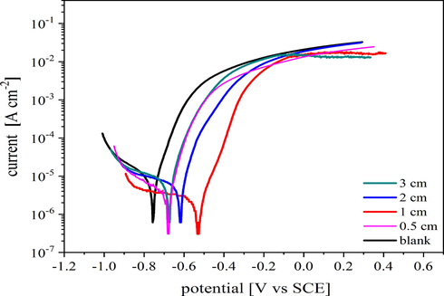
Potentiodynamic polarization curves of untreated and plasma-treated steel at different gap distances of the electrodes in 3.5% NaCl at room temperature (30°) using a scan rate of 1 mV s−1.
The enhancement of both cathodic and anodic reactions of treated steel compared to the untreated ones were recorded a more pronounced enhancement was observed in the anodic reaction compared to the cathodic one. The associated electrochemical parameters such as corrosion current density (
), corrosion potential (Ecorr), corrosion rate (Kcorr), corrosion inhibition efficiency (
%), anodic, and cathodic Tafel slope (
,
) are shown in Table 1. The
values are significantly decreased by reducing the gap distance and reaches a minimum at 1 cm gap distance. The corrosion current (
) is reduced from 12 µA/cm2 for the blank sample to 2.942 and 0.714 µA/cm2 for treated samples at gap distances 2, and 1 cm, respectively. The sharp decrease of the corrosion current density indicates a large inhibition of localized corrosion, such as pitting corrosion. This means the protective coating blocks the defects in the steel substrate and prevents the penetration of Cl− ions through it.
Gap distance
Icorr
(µA/cm2)
Ecorr
(mV VS SCE)
βa
(mV.dec−1)
βc
(mV.dec−1)
K
(mm/year)
Ƞpol
%
blank
12.001
−809.3
115.00
−203
0.08981
ــــــــــــ
3.0 cm
07.351
−711.4
101.00
−325
0.05501
38.74
2.0 cm
02.942
−624.3
064.75
−310
0.02201
75.48
1.0 cm
00.714
−534.7
067.54
−316
0.00534
94.05
0.5 cm
06.264
−767.1
102.00
−224
0.04688
47.80
The protective efficiency reaches to 94.05 and 75.48% for 1 and 2 cm, respectively. Moreover, the protective coatings increase the corrosion potential of the steel substrate from −0.8093 V to −0.5347 V, −0.6243 V, and −0.7114 V vs. SCE, for 1, 2 and 3 cm gap distance, respectively. The difference in Ecorr between the plasma deposited samples and the blank are more than 85 mV and shifted to more positive values. This is an indication that the silicon oxycarbide thin film highly retarded the anodic dissolution of steel.
Potentiodynamic results indicated that silicon oxycarbide thin films provide effective protection with efficiency up to 94.05 and 75.48% for 1 and 2 cm gap distance, respectively. The protective action of such film might be attributed to its chemical structure (SiO2-like) which is mainly composed of the Si-O-C and Si-O-Si backbone, both of which are an essential key for metal protection (Saloum et al., 2018).
3.1.2 Electrochemical impedance spectroscopy (EIS)
The corrosion behavior of plasma-treated samples was also measured using EIS in a 3.5% NaCl solution at 30 °C and the results are explained in terms of Bode and Nyquist plots. According to the Nyquist plot Fig. 3a and Bode plot Fig. 3b and c, all plasma-treated samples exhibit two capacitive loops which account for two different time constants. The first loop observed at high frequencies correspond to the properties of the protective silicon oxycarbide layer and the second one at lower frequencies is characteristic for the steel substrate-electrolyte interaction (Anagri et al., 2019). The impedance spectra were analyzed by fitting the experimental data to an equivalent circuit model composed of two-time constants as shown in Fig. 3d, and the different EIS parameters such as film resistance (Rf), double-layer capacitance (Cdl), charge transfer resistance (Rct), constant phase element (Y0 and n) and efficiency of inhibition (
%) are listed in Table 2. The parameters in Table 2 were obtained by fitting the experimental EIS data using the fitting tools in ZSim 3.30d software.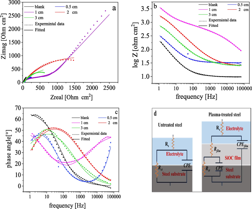
EIS analysis of base material and plasma-treated samples in 3.5% NaCl at room temperature (30°). (a) Nyquist plot, (b and c) Bode plots, and (d) the electrical equivalent circuit used to fit EIS data.
Gap distance
Rs
(Ω cm2)
Rct
(Ω cm2)CPE
Rf
(Ω cm2)Cf
Cdl
(μF cm−2)Chi- square
(χ2)
ηEIS
%
Yo
(μ Ω −1 sn cm−2)n
Yo
(μ Ω−1 sn cm−2)n
Blank
9.6
200.5
1200.00
0.73
-----
-----
-----
708.50
1.4 × 10⁻³
-----
0.5 cm
27.3
319.2
0.05
0.92
727.2
620.0
0.73
0.02
4.3 × 10⁻³
37.18
1 cm
89.5
3565.5
09.80
0.53
6300
88.0
0.61
0.50
1.1 × 10⁻³
94.37
2 cm
25.43
1739.6
62.30
0.73
3152
37.7
0.72
27.30
5.2 × 10⁻⁴
88.47
3 cm
26.2
387.0
300
0.62
10.54
300
0.79
80.15
3.3 × 10⁻³
48.19
The fitted data indicate that the chi-square (χ2) values are around 10−3. The lower value of χ2 indicates a good agreement between the fitted data and the experimental results.
Constant phase element (CPE) was used in order to deal with the non-ideal capacitance response. The impedance of the constant phase element (ZCPE) and the double-layer capacitance (Cdl) are calculated by using Eqs. (4) and (5):
Nonetheless, (n) determines diverse physical phenomena such as surface heterogeneity results from surface roughness, inhibitor porous layer formation and degree of polycrystallinity. The values of n merely reflect the surface homogeneity of the Si-O-C layer.
The double-layer capacitance (Cdl) is significantly decreased after plasma deposition because of the nature of the organosilicon layer which acts as a barrier layer and slows down the interaction between the electrolyte and steel substrate. Cdl values were decreased due to a decrease in the local dielectric constant and/or an increase in the thickness of the electrical double layer.
Furthermore, the Bode plot obtained for untreated steel showed a capacitive loop in the low-frequency region. After the film deposition, the low-frequency maximum is still detected but a more intense component was developed in the high-frequency region. The second maximum correspond to electrolyte-film interactions and the presence of the two components suggests simultaneous reactions on the film and substrate surfaces takes place. The presence of small pores in the protective film that allow electrolytes to reach the steel substrate, and the onset of a low-frequency time constant might be the reason.
Moreover, the growth in the high-frequency (HF) maxima is accompanied by a drop in the low-frequency one, reveals a better performance of the system under the corrosive medium (Smith et al., 2015; Li et al., 2010). EIS results revealed good corrosion behavior of carbon steel coated with silicon oxycarbide thin films, which is in good agreement with potentiodynamic polarization analysis.
In conclusion, the 1 cm gap distance is the optimum gap distance for the deposition of an effective film against corrosion.
3.1.3 Influence of pH values on the corrosion performance
In order to get a more in-depth electrochemical investigation, a new series of samples were prepared using TEOS/ plasma and the gap distance was fixed at 1 cm. The electrochemical properties of newly prepared samples were inspected in various buffer solutions with different pH values. The electrochemical behavior of plasma-treated steel was tested in solutions with different pH values by electrochemical impedance spectroscopy (EIS). Fig. 4 displays the Bode plots of treated samples in comparison to the untreated ones in different pH solutions (1, 3, 5, 9, and 12). The untreated sample exhibits almost a similar behavior in all buffer solutions, which give a concavity shape with a maximum around 101 Hz.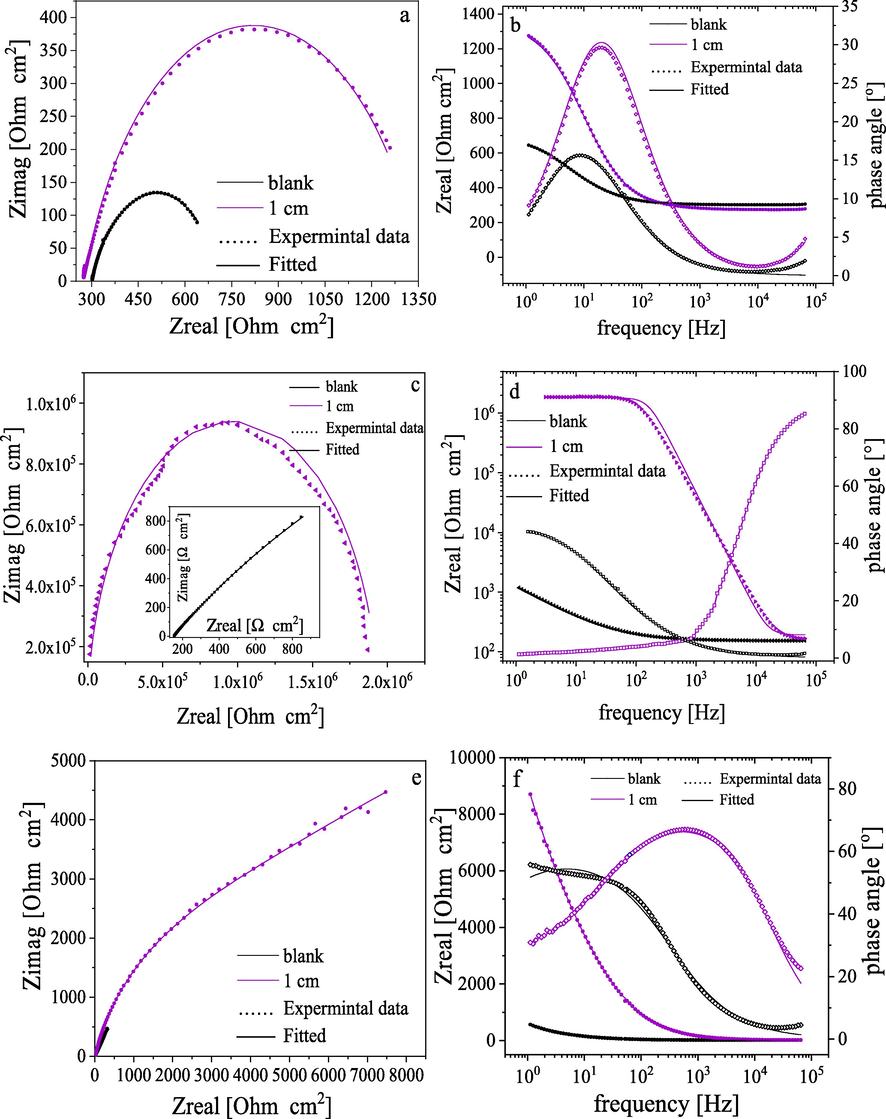
Examples of EIS plots of plasma-treated samples in phthalate buffer solutions with different pH as: Nqusit (a, c, and e), and Bode (b, d and f) for pH 3, 9 and 12 at room temperature (30°).
For the plasma-treated sample, the HF loop was detected in all pH solutions and in the solution with pH 9 indicating a great improvement in the corrosion resistance of the treated carbon steel in this medium (Rangel et al., 2019). Moreover, the presence of only one concavity at the high-frequency region suggests that there is no interaction between the solution and steel substrate. Therefore, the film entirely isolates the steel substrate from the corrosive electrolyte (Barranco et al., 2004; Yadav et al., 2019) which will be further confirmed in a later section through SEM investigations.
Also, it is worth noting that the phase angle was elevated to be ∼ 80° and 90° in the case of pH 9 and 12, respectively as presented in Fig. 4 d and f. This variation reveals the capacitive behavior of the coatings which retard the flow of oxidative species through it (Rangel et al., 2019).
The Bode plots also demonstrate the impedance as a function of the frequency where the impedance increases with decreasing frequency achieving the highest value at the low-frequency extreme. The total resistance of system Rt (Rt = Rct + Rs) was derived from the impedance/frequency curve at the lowest frequency extreme (10−1 Hz) (Rangel et al., 2020).
The obtained impedance was presented in Table 3 and it was seen that the highest impedance was observed in alkaline solutions with inhibition efficiency 99.58 and 93.49% for pH 9 and 12, respectively. However, the highly acidic solutions are aggressive towards coating causing cracks, pinholes, or other kinds of defects that may originate from the partial rupture of films allowing the electrolyte to diffuse through the film reaching the substrate.
pH
Sample
Rs (Ω cm2)
Rct (Ω cm2)
CPE Yo (μ Ω −1 sn cm−2)
Rf
Cf
Yo (μ Ω −1 sn cm−2)
Cdl (μF cm−2)
Chi- square v
ηEIS %
1
Blank
46.70
269.6
110.00
0.80
-----
-----
-----
45.60
1.9 × 10⁻⁴
-----
1 cm
46.08
584.2
57.00
0.87
18.25
5400
0.66
34.20
6.7 × 10⁻⁵
53.83
3
Blank
300.90
415.5
190.00
0.76
-----
-----
-----
85.20
7.0 × 10⁻⁵
-----
1 cm
278.66
996.5
0.065
0.86
1089
45
0.78
0.01
1.4 × 10⁻⁴
58.30
5
Blank
180.70
56.8
1.17
0.93
-----
-----
-----
0.56
1.5 × 10⁻³
-----
1 cm
177.38
182.0
0.027
0.78
160.9
6.14
0.88
8.5 × 10⁻⁴
1.3 × 10⁻³
68.79
9
Blank
151.50
7772.0
240.00
0.71
-----
-----
-----
309
6.5 × 10⁻⁵
-----
1 cm
167.30
1.89 x10⁶
1.7 x10⁻⁴
0.89
16,000
1.6 × 10⁻³
0.76
6.2 × 10⁻⁵
1.1 × 10⁻¹
99.58
12
Blank
14.40
566.3
43.00
0.67
-----
-----
-----
6.89
1.1 × 10⁻³
-----
1 cm
14.93
8705.2
5.40
0.80
3500
53
0.44
2.51
8.0 × 10⁻⁴
93.49
The electrochemical performance of silicon oxycarbide films in the alkaline solution can be explained through the following statement.
The strong alkaline solutions (pH more than 9) are OH-rich which can break the polarized Si-O-Si bond in the amorphous silicon oxycarbide matrix (Sorarù et al., 2002).
3.2 Surface morphology
The surface of the steel before plasma treatment was smooth and crack-free as shown in Fig. 5a. Moreover, the impact of plasma treatment on the morphological features of steel was studied for a gap distance of 1 cm between plasma electrodes as an example (optimum gap distance) using the SEM as presented in Fig. 5c and show that the mild steel was covered by a homogeneous layer.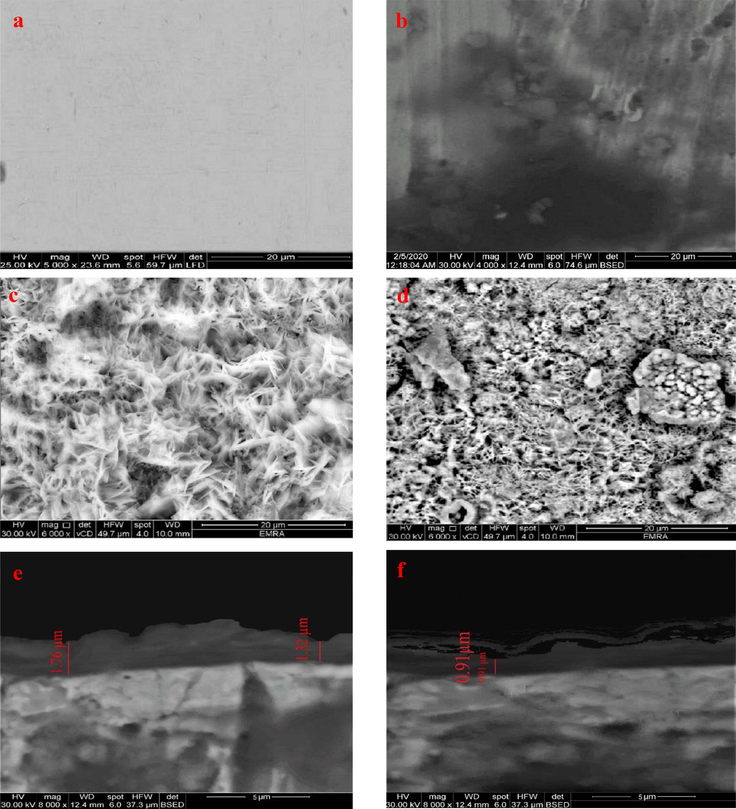
SEM image of carbon steel sample: blank (untreated) (a), blank sample after 24-hour immersion in 3.5% NaCl solution (b), the deposited sample with a gap distance 1 cm as an example (c), the deposited sample with a gap distance 1 cm after 24-hour immersion in 3.5% NaCl solution (d), cross-section of the treated sample with a gap distance 1 cm (e), cross-section of the treated sample with a gap distance 1 cm after 24-hour immersion in 3.5% NaCl (f).
Fig. 5b reveals the surface morphology of the untreated sample after 24-hour dipping in a 3.5% NaCl solution. The steel surface was damaged by pitting corrosion caused by chloride ions attacked the steel surface. Conversely, the plasma-treated samples after dipping show considerable improvement as presented in Fig. 5d. The corrosive medium caused some of the ruptures on the protective layer, but the steel below it was protected, which confirms that plasma/TEOS treatments provide a good protection for the steel against corrosion.
Moreover, the cross-section view of the coating (Fig. 5e) shows that the thickness of the deposited layer was in the range from ∼ 1.3 to 1.8 µm. The cross-section view after 24-hour immersion in 3.5% NaCl was revealed in Fig. 5f and displays a strong superficial damage of the protective layer but still covers the steel sample and isolates it from corrosive solution. Additionally, the SEM images of 2 and 3 cm gap distance are presented in Fig. S1 and show that the homogeneity of the deposited film gets worse by increasing the gap distance between two electrodes.
The effect of pH of corrosive solution on the morphological feature of plasma-treated carbon steel was revealed in Fig. 6a and 6b. The corrosive medium (pH 1) caused strong pitting on the protective layer, but the film still appears united and shows a spongy-like structure (Fig. 6a). Contrastingly, the surface of SiOC layer exhibits a very protected surface after 24 h immersing in pH 9 solution and appeared homogeneously structured, with little pits and cracks (Fig. 6b). This can potentially account for unique electrochemical results of plasma-treated samples in this medium.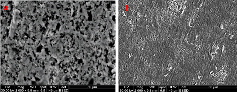
SEM images of plasma-treated steel samples with 1 cm gap distance after 24-hour immersion in solution with pH: (a) 1, (b) 9 at 30°.
Finally, the plasma-treated samples display a great stability in neutral and alkaline mediums confirming the plasma/TEOS treatments afford good protection for the steel against corrosion in these mediums and agreeing well with the electrochemical measurements results.
3.3 Elemental analysis using energy dispersive analysis of X-ray (EDX)
The elemental composition of the deposited film was estimated using EDX analysis, the obtained results were revealed in Table 4.
Gap distance (cm)
Element (At%)
Fe
Si
O
C
O/Si
C/Si
blank
99.36
00.00
00.00
00.64
----
------
0.5
74.97
2.22
04.11
18.70
1.85
8.42
1.0
40.01
9.43
11.16
39.40
1.18
4.17
2.0
80.72
3.60
04.52
11.16
1.25
3.22
3.0
96.53
1.64
01.83
00.00
1.11
-----
Silicon, oxygen, and carbon were detected in all of the treated samples. Moreover, it was found that the atomic percentages (At%) of previous elements had a regular trend in dependence on the gap distance between the two electrodes indicating the gap distance is an influential parameter in the plasma deposition. However, the sample with 1 cm gap distance contained the highest Si, O, and C (At%), and the lowest Fe (At%) in the limit of the EDX. Conversely, a 3 cm gap distance sample holds the lowest Si and O content while the carbon content is undetectable. The enhancement of the deposition process with the reduction of the gap distance may be attributed to the fact that the TEOS molecules were fragmented in the vapor-plasma phase generating highly reactive species. These fragments are immediately randomly recombined with each other (Fahmy et al., 2012). This condensation is taking place on the steel electrode surface forming a highly cross-linked interfacial layer which may provide good corrosion protection (Vassallo et al., 2006). Furthermore, the species leading to film growth are the radicals rather than the ions. The ions which are accelerated in the sheaths mainly contribute to ion bombardment and structural rearrangement of the growing layer. As results, the films consist of various silicon oxycarbide, silicon carbide, or silicon oxide matrix (SiO2 like) based on the gap distance between the electrodes. When the two electrodes get closer to each other (less than 1 cm), fragment ions were deposited on the substrate. In this case, the plasma sheath on the two electrodes is interfered and minimized the deposition rate of films. In addition to the fragmentation of the monomer and poly-recombination, the area of plasma energy, in such case, is very small leading to etching of the layers that are already deposited (Scheme. 1) (Fahmy and Friedrich, 2013).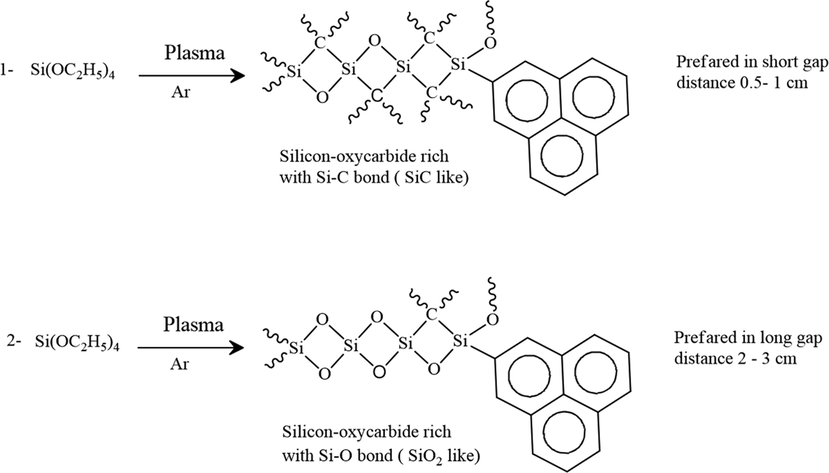
Suggested reactions mechanisms of TEOS in plasma phase.
TEOS (theoretically) consists of Si (07.7), O (30.8), C (61.5) atomic percent, therefore, it can be noted that the composition of the deposited layer might be mainly silicon oxycarbide (Si-O-C This suggestion is proven later by FTIR measurements.
Table 5 presents the elemental percentages (At%) of thin films deposited at optimum gap distance (1 cm), after 24 h immersion in various pH solutions. The obtained results reveal that silicon oxycarbide has a great stability in the neutral and alkaline mediums.
pH
Element (At%)
ratios
Fe
Si
O
C
Na
Cl
B
K
O/Si
C/Si
1
78.67
03.13
5.07
08.79
-----
04.34
-----
-----
1.62
2.8
6.5(3.5% NaCl)
60.36
5.24
7.20
24.69
1.19
1.32
-----
-----
1.37
4.7
9
55.3
7.3
10.46
26.39
0.15
0.25
0.05
0.10
1.43
3.6
3.4 Chemical bonding of the deposited layer
The structure of the deposited films was investigated using FTIR in ATR mode as mentioned previously. The absorbance bands of deposited films with 1 and 2 cm gap distance (as examples) were selected and presented in Fig. 7. All treated samples have similar peaks, confirming that they have the same film composition however, the intensity of the peaks diminishes as the gap distance increases. The presence of absorption bands in the range from 440 to 1340 cm−1 can be referred to as different vibration modes of the oxygen– silicon bridge (Si-O-Si) (Kakiuchi et al., 2012). Rocking, bending, and stretching of the Si-O bond in Si-O-Si are revealed by the bands in ∼ 440, 810, and 1050 cm−1, respectively. Furthermore, the absorption bands ranging from 1375 to 1444, 1520–1830, and 2200 cm−1 correspond to CHx bending vibrations, (C = C; C = O), and Si–H, respectively (Pfuch and Cihar, 2004; Cho and Boo, 2012).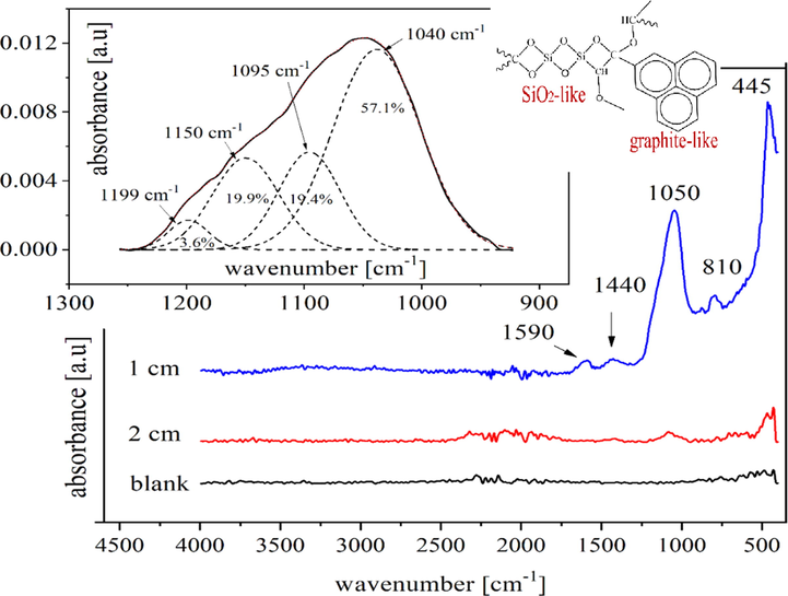
FTIR spectra of plasma deposited films based on the gap distance 1 and 2 cm compared to the blank sample.
The inset of Fig. 7 shows the spectra of the deposited film with a 1 cm gap distance in the range from 1250 to 910 cm−1 to quantitatively contribute to the embedded silicon content using Gaussian functions in Origin software, version 2018. Wavenumbers were given along with the calculated intensities in percentages based on the area under the peak and the regression coefficient was better than 0.999.
Peaks at 1050–1150 cm−1 are characteristic of Si–O–Si, Si–O–C, and C–O–C stretching. The broad peak at 1095 cm−1 correspond to the C–O stretching vibration (Fahmy et al., 2011) while the detected band at 1040 cm−1 confirms the formation of Si–O bonds results from the Si-O–C covalent bond while the peak that monitored at ∼ 1200 cm−1 is corresponding to C-O-C (Xie et al., 2011). The C–O and Si–O stretches are predictable at 1095–1150 cm−1 (The inset of Fig. 7), therefore, named as antisymmetric and symmetric Si–O–C stretches (Fahmy et al., 2020).
Thus, it can be assumed that the deposited film composes mainly of a silicon-oxycarbide matrix. In detail, silicon oxycarbide is a crosslinked material that has a structure resembling a silicon dioxide network (SiO2) containing some carbon atoms instead of the oxygen in the tetrahedral network and is generally described as (SiOxCy) (Vassallo et al., 2006). Also, carbon can exist as a free carbon phase form (graphite-like phase) (Yang et al., 2005; Sen et al., 2013). The silicon oxycarbide network is classified into SiO2- like or SiC- like constituents based on the amount of incorporated carbon in the network (Niemiec et al., 2018). Since the FTIR data does not specify any distinct peaks of Si-C, this meaning that not much carbon has been incorporated into the silicon oxycarbide matrix which confirms that the deposited film is SiO2 like.
3.5 Crystallinity
The crystalline structure of untreated / treated steel samples was examined by XRD and is presented in Fig. 8. In the XRD survey all treated samples (based on the gap distance) exhibit the same diffraction patterns compared to the one obtained with the untreated sample. Two θ (°) 44.3 and 64.8° for reflection from plans 220 and 400, respectively were observed (Anantharaman and Al-Omari, 2012). Treated samples with gap distances 0.5 and 3 cm show peaks (44.3 and 64.8°) in the similar position of the untreated sample and lower intensities compared to the blank ones. While the treated samples with gap distances 1 and 2 cm are shifted to lower 2θ. This provides strong evidence that the silicon compound incorporates as an interstitial impurity in the steel lattices causing expansion due to such incorporation (Sethi and Bhat, 2019). It can be concluded that the deposited films in case of gap distance 1 and 2 cm are chemically bonded to the mild steel substrate.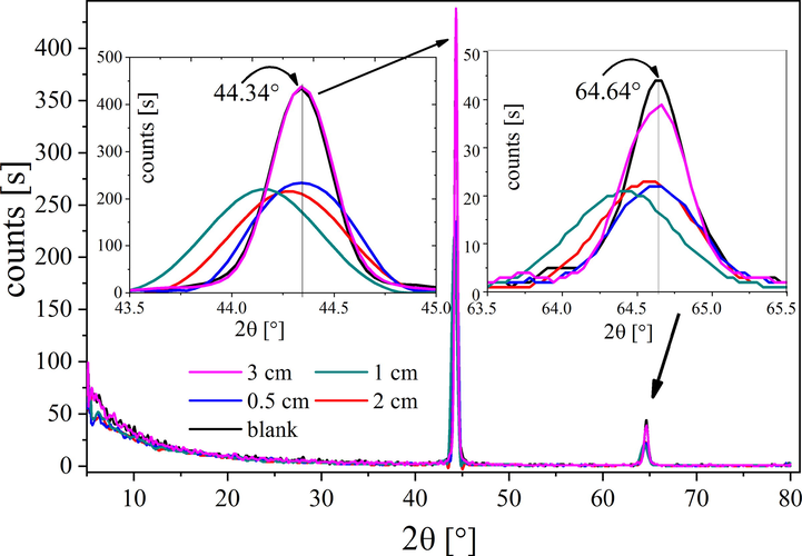
XRD patterns of treated samples at different gap distances between the two electrodes.
4 Conclusions
In this study, a thin silicon oxycarbide film was deposited by rf plasma discharge on steel substrates using tetraethyl orthosilicate (TEOS) as a precursor at room temperature. The structure/property relationships of treated samples were investigated based on the gap distance between the electrodes. FTIR and XRD analysis show the formation of a silicon oxycarbide protective layer with high content of oxygen. The morphological study reveals that the resulting silicon oxycarbide layer is highly crosslinked, and physically stable. The homogeneity of deposited films is strongly dependent on gap distance and the better homogeneity was obtained at 1 cm gap distance which provides good corrosion protection for carbon steel.
Polarization and electrochemical impedance spectroscopy methods have been used to characterize the electrochemical performance of carbon steel coated with silicon oxycarbide films in different pH electrolytes at room temperature. The deposited silicon oxycarbide layer provided high corrosion resistance for low carbon steel in neutral and alkaline mediums with a protection efficiency of more than 99% in pH 9. Moreover, this film represented an interesting alternative for improving the anticorrosion performance of carbon steel in easily and cost-effective method.
Acknowledgments
The authors gratefully acknowledge financial support from Taif University Researchers Supporting Project number (TURSP-2020/135), Taif University, Taif, Saudi Arabia.
We also thank Mr. Hassan Omar (6.6 Physics and chemical analysis of polymers, BAM Berlin, Germany) for helping to improve the language of the article.
Declaration of Competing Interest
The authors declare that they have no known competing financial interests or personal relationships that could have appeared to influence the work reported in this paper.
References
- Abu-Saied, M., Fahmy, A., Morgan, N., Qutop, W., Abdelbary, H., Friedrich, J.F., 2019. Enhancement of poly (vinyl chloride) electrolyte membrane by its exposure to an atmospheric dielectric barrier discharge followed by grafting with polyacrylic acid. Plasma Chemistry and Plasma Processing 39, 1499–1517.
- Silica doped with lanthanum sol–gel thin films for corrosion protection. Thin Solid Films. 2012;520:5267-5271.
- [Google Scholar]
- Evaluation of the corrosion protection performance of mild steel coated with hybrid sol-gel silane coating in 3.5 wt.% NaCl solution. Prog. Org. Coatings. 2018;123:190-200.
- [Google Scholar]
- Nanocomposite coatings based on graphene and siloxane polymers deposited by atmospheric pressure plasma. Application to corrosion protection of steel. Surf. Coat. Technol.. 2019;377:124928
- [Google Scholar]
- Anantharaman, M.R., Al-Omari, I.A., 2012. The Effect of Antimony Substitution on the Magnetic and Structural Properties of Fe0. 75–xSi0. 25Sbx Alloys.
- Correlation of morphology and barrier properties of thin microwave plasma polymer films on metal substrate. Electrochim. Acta. 2004;49:1999-2013.
- [Google Scholar]
- Corrosion behavior of TiO2–NiO nanocomposite thin films on AISI 316L stainless steel prepared by sol–gel method. Thin Solid Films. 2012;522:289-296.
- [Google Scholar]
- Characteristics of multilayered plasma-polymer thin films using toluene and TEOS by PECVD. Microelectron. Eng.. 2012;89:19-22.
- [Google Scholar]
- Investigation of the corrosion protection of SiOx-like oxide films deposited by plasma-enhanced chemical vapor deposition onto carbon steel. Electrochim. Acta. 2010;55:8921-8927.
- [Google Scholar]
- The effect of solution pH on the electrochemical performance of nanocrystalline metal ferrites MFe 2 O 4 (M= Cu, Zn, and Ni) thin films. Appl. Nanosci.. 2016;6:485-494.
- [Google Scholar]
- Fahmy, A., Abu-Saied, M., Organ, N., Qutop, W., Abdelbary, H., Salama, T., 2019. Surface modification of polyvinyl chloride by polyacrylic acid graft as a polyelectrolyte membrane using Ar plasma. Turkish Journal of Chemistry 43, 1686–1696.
- Influence of water addition on the structure of plasma-deposited allyl alcohol polymer films. J. Adhes. Sci. Technol.. 2015;29:965-980.
- [Google Scholar]
- Degradation Behavior of Thin Polystyrene Films under Exposure to Ar-Plasma and its Emitted Radiation. J. Adhes. Sci. Technol.. 2013;27:324-338.
- [Google Scholar]
- Structure of Plasma-Deposited Poly (acrylic acid) Films. Plasma Processes Polym.. 2011;8:147-159.
- [Google Scholar]
- Surface and Bulk Structure of Thin Spin Coated and Plasma-Polymerized Polystyrene Films. Plasma Chem. Plasma Process.. 2012;32:767-780.
- [Google Scholar]
- Structure/property relationship of polyvinyl alcohol/dimethoxydimethylsilane composite membrane: Experimental and theoretical studies. Spectrochim. Acta Part A Mol. Biomol. Spectrosc.. 2020;228:117810
- [Google Scholar]
- One-step plasma deposited thin SiO x C y films for corrosion resistance of low carbon steel. J. Adhes. Sci. Technol.. 2021;35:1734-1751.
- [Google Scholar]
- Gangan, A., El Sabbagh, M., Bedair, M., El-Sabbah, M., Fahmy, A., 2020. Plasma Power Impact on Electrochemical Performance of Low Carbon Steel Coated By Plasma Thin Teos Films. Al-Azhar Bulletin of Science 31, 51–58. https://doi.org/10.21608/absb.2020.111474
- Improving the bio-corrosion behavior of AISI316L stainless steel through deposition of Ta-based thin films using PACVD. Appl. Surf. Sci.. 2018;456:398-402.
- [Google Scholar]
- Silicon oxide coatings with very high rates (> 10 nm/s) by hexamethyldisiloxane-oxygen fed atmospheric-pressure VHF plasma: film-forming behavior using cylindrical rotary electrode. Plasma Chem. Plasma Process.. 2012;32:533-545.
- [Google Scholar]
- Corrosion inhibition of aluminum and aluminum alloys by soluble chromates, chromate coatings, and chromate-free coatings. Corrosion. 2003;59:379-400.
- [Google Scholar]
- Surface modification of low-carbon steels by plasma electrolytic nitrocarburising. Plasma Chem. Plasma Process.. 2016;36:1271-1286.
- [Google Scholar]
- Protective SixOyCz coatings on steel prepared by plasma activated chemical vapour deposition. Surf. Coat. Technol.. 2010;204:2813-2816.
- [Google Scholar]
- Corrosion and tribo-corrosion behavior of a-SiCx: H, a-SiNx: H and a-SiCxNy: H coatings on SS301 substrate. Surf. Coat. Technol.. 2010;204:1616-1622.
- [Google Scholar]
- Measure and evaluate the hardness of the electrodeposited Nickel-Phosphorous (Ni-P) thin film coating on carbon steel alloy for automotive applications. Measurement. 2019;139:490-497.
- [Google Scholar]
- IR investigation on silicon oxycarbide structure obtained from precursors with 1: 1 silicon to carbon atoms ratio and various carbon atoms distribution. J. Mol. Struct.. 2018;1164:217-226.
- [Google Scholar]
- On low pressure plasma processing for metal protection. Plasma Processes Polym.. 2009;6:S684-S689.
- [Google Scholar]
- Deposition of SiOx thin films by microwave induced plasma CVD at atmospheric pressure. Surf. Coat. Technol.. 2004;183:134-140.
- [Google Scholar]
- Chromate conversion coatings and their current application. Metalurgija. 2016;55:253-256.
- [Google Scholar]
- Investigation of the densification mechanisms and corrosion resistance of amorphous silica films. J. Non-Cryst. Solids. 2019;515:34-41.
- [Google Scholar]
- Barrier and mechanical properties of carbon steel coated with SiOx/SiOxCyHz gradual films prepared by PECVD. Surf. Coat. Technol.. 2019;378:124996
- [Google Scholar]
- Role of the Plasma Activation Degree on Densification of Organosilicon Films. Materials. 2020;13:25.
- [Google Scholar]
- Electrochemical study of TEOS, TEOS/MPTS, MPTS/MMA and TEOS/MPTS/MMA films on tin coated steel in 3.5% NaCl solution. Prog. Org. Coat.. 2012;74:288-301.
- [Google Scholar]
- Influence of annealing temperature on the structural and anti-corrosion characteristics of sol–gel derived, spin-coated thin films. Ceram. Int.. 2014;40:2885-2890.
- [Google Scholar]
- Plasma polymerized hexamethyldisiloxane thin films for corrosion protection. Mod. Phys. Lett. B. 2018;32:1850036.
- [Google Scholar]
- Carbon substitution for oxygen in silicates in planetary interiors. Proc. Natl. Acad. Sci.. 2013;110:15904-15907.
- [Google Scholar]
- Facile solvothermal synthesis and high supercapacitor performance of NiCo2O4 nanorods. J. Alloy. Compd.. 2019;781:1013-1020.
- [Google Scholar]
- Economic risk analysis of pitting corrosion in process facilities. Int. J. Press. Vessels Pip.. 2017;157:51-62.
- [Google Scholar]
- Deposition of Ni coatings by electrolytic plasma processing. Plasma Chem. Plasma Process.. 2015;35:963-978.
- [Google Scholar]
- Chemical durability of silicon oxycarbide glasses. J. Am. Ceram. Soc.. 2002;85:1529-1536.
- [Google Scholar]
- Preparation of plasma-polymerized SiOx-like thin films from a mixture of hexamethyldisiloxane and oxygen to improve the corrosion behaviour. Surf. Coat. Technol.. 2006;200:3035-3040.
- [Google Scholar]
- Sol–gel derived poly (vinyl alcohol)/maleic acid/silica hybrid membrane for desalination by pervaporation. J. Membr. Sci.. 2011;383:96-103.
- [Google Scholar]
- Synthesis of zirconium diboride and its application in the protection of stainless steel surface in harsh environment. J. Solid State Electrochem.. 2019;23:3243-3253.
- [Google Scholar]
- Microstructure and tribological properties of SiOx/DLC films grown by PECVD. Surf. Coat. Technol.. 2005;194:128-135.
- [Google Scholar]
- Smart inorganic and organic pretreatment coatings for the inhibition of corrosion on metals/alloys. Intelligent Coatings Corrosion Control 2015:59-91.
- [Google Scholar]
Appendix A
Supplementary material
Supplementary data to this article can be found online at https://doi.org/10.1016/j.arabjc.2021.103391.
Appendix A
Supplementary material
The following are the Supplementary data to this article:


