

Translate this page into:
Synergistic effect of surface reconstruction and rGO for FeS2/rGO electrocatalysis with efficient oxygen evolution reaction for water splitting
⁎Corresponding authors at: 1 Hunan Road, Liaocheng City, Shandong Province, China (Xiaozhen Ren). 2699 Qianjin Dajie, Chaoyang District, Changchun City, Jilin Province, China (Hua Yang). renxiaozhen@lcu.edu.cn (Xiaozhen Ren), huayang86@sina.com (Hua Yang)
-
Received: ,
Accepted: ,
This article was originally published by Elsevier and was migrated to Scientific Scholar after the change of Publisher.
Peer review under responsibility of King Saud University.
Abstract
Exploring highly active and inexpensive electrocatalysts for oxygen evolution is vital but challenging. Herein, a serial of FeS2, FeS and FeS2/rGO electrocatalysts were obtained by simple two-step method. Benefiting from the integration of FeS2 and rGO, the FeS2-450/rGO-10% exhibited the excellent catalytic activity toward OER with an ultra-low overpotential of 140 mV, a smaller Tafel slope of 71 mV/dec and high stability. The improved catalytic performance for OER could attribute to the excellent synergistic effect of the surface reconstruction of FeS2 and the introduction of rGO in FeS2-450/rGO-10% catalyst. Meanwhile, in a two-electrode system of FeS2-450/rGO-10%/NF//Pt/C/NF toward overall water splitting, the voltage at 10 mA cm−2 is only 1.52 mV, which indicates that the FeS2-450/rGO-10% can serve as the anode in practical overall water splitting.
Keywords
Iron sulfide
Self reconstruction
Electron transfer channel
Water splitting
Synergistic effect

1 Introduction
To approach carbon neutrality by 2050/2060, it is urgent to develop clean energy. As a kind of green and pollution-free energy, hydrogen energy has received more and more attention. Electrochemical water splitting, which contains two half reactions: the oxygen evolution reaction (OER) and hydrogen evolution reaction (HER), is one of an effective way to produce hydrogen energy (Wang et al., 2023; Wu et al., 2022). Compared with HER, OER is more complicated due to its slow-moving kinetics of four electrons transfer, which needs large overpotential (Li et al., 2018a; Xu et al., 2021). Therefore, we should pay much attention to explore a suitable catalyst to reduce the energy barrier for OER. Up to now, noble metal-based materials, such as InO2 or RuO2, are the state-of-the-art OER electrocatalysts because of their high efficiency (Audichon et al., 2016; Wu et al., 2016). Whereas, their widespread practical production has been severely inhibited due to the scarcity and high price. Therefore, we must explore highly cost-efficient and earth-abundant OER electrocatalysts for practical application.
Among a wide variety of noble metal-free electrocatalysts for OER, transition metal-based nanomaterials having high catalytic activity are promising alternatives, such as transition metal oxides (Gao et al., 2014), carbides (Roy et al., 2021), nitrides (Li et al., 2022), sulfides (Jiang et al., 2021; Ren et al., 2022) and phosphides (Jin et al., 2014). Many strategies, such as defecting regulation, heterostructure construction and morphology engineering et al. have been used to improve their OER activity and stability. Meanwhile, some researchers have focused on the surface structure, such as crystallinity, surface defects and oxidation state to explore the catalytic active sites. Yu et al. stated that the amorphous CoSx had transformed into CoOOH after OER, which served as the active species (Fan et al., 2018). In Chen’s report, the FeNi2S4 catalysts had in situ reconstructions of FeNi-based hydroxides or oxides (Jiang et al., 2021). Especially, owing to the low intrinsic resistivity, low cost, earth-abundance and high stability, FeS2 has attracted more attention as a promising catalyst for OER. Although some FeS2-based catalysts have been reported, the surface structure changing is rarely studied, which is crucial to found the active sites for the FeS2-based catalysts. Wang et al. found that the surface of FeS2 had self-reconstruction to amorphous/crystalline hybrid FeS2 after OER (Wang et al., 2021).
Considering the potential practical application, we should make much effort to further improve the catalytic activity and stability of the FeS2-based catalysts. Among all kinds of constraints, electrical conductivity is one of the most critical factors in electrocatalytic efficiency for improving the activity and stability. Graphene and nano carbons can improve the OER activity and stability of the FeNi2S4 by integrating with carbon (Jiang et al., 2021). Also, the FeS2/C nanoparticle has been constructed, and the overpotential at 10 mA cm−2 was 240 mV toward OER for the catalyst (Li et al., 2018b). But this report did not concern the surface structure changing after OER. Given the importance of the surface structure, it is necessary to study the surface structure of the FeS2-C-based catalyst after OER and the synergistic effect of surface structure and introduction of carbon material.
In this paper, serials of FeS2 and FeS electrocatalysts was prepared by simple two-step method. Meanwhile, a series of FeS2-450/rGO-x% (x = 5, 10 and 15) catalysts were also prepared using the same method by adding GO in the hydrothermal step. FeS2-450/rGO-10% showed better catalytic activity and stability than the commercial RuO2 or FeS2-450 catalysts. The excellent synergistic effect of surface reconstruction of FeS2 and the introduction of rGO in FeS2-450/rGO-10% catalyst were discussed detailed. This will open up new avenues for preparing transition metal disulfide and for their potential practical application.
2 Experimental
2.1 Materials preparation
2.1.1 Preparation of FeS2 and FeS materials
Typically, 0.6 g Lysine was added to 75 mL FeCl3 solution (0.05 M) and the solution was continuously stirred at 40 °C for 0.5 h. Then, 4 mL NH3·H2O (32 wt%) was added into the above solution with dropping in 0.5 h. Then, the solution was transferred into a 100 mL Teflon-lined autoclave and heated at 180 °C for 6 h. After cooling to room temperature, the precipitate was filtered, washed and dried at 60 °C for 8 h. After that, the obtained powder and sulfur powder were mixed uniformly with continuous grinding for 0.5 h. Finally, the FeS2 and FeS samples were obtained by heating the mixed powder to a certain temperature for 4 h in N2 with a heating rate of 3 °C/min. The samples were marked with FeS2-400, FeS2-450, FeS2-550, FeS-650, and FeS-750, with calcination temperature of 400 °C, 450 °C, 550 °C, 650 °C and 750 °C, respectively.
2.1.2 Preparation of FeS2-450/rGO-x% (x = 5, 10 and 15) materials
The synthesis procedure of FeS2-450/rGO-x% (x = 5, 10 and 15) materials is similar to preparing the FeS2-450 sample, excepting a mount of GO was added into the initial FeCl3 solution. The synthesis process of the FeS2-450/rGO-x% catalysts has been displayed in Scheme 1 and can be explained according to Eq. (1) to (3). Under the alkaline environment, Fe3+ adsorbed on GO converted into Fe2O3 during the hydrothermal stage, while the GO was reduced to rGO, forming Fe2O3/rGO (Eqs. (1) and (2)), as shown in Fig. S1. Under the inert atmosphere of 450 °C, the mixed Fe2O3/rGO and S powder transformed into FeS2-450/rGO and H2O (Eq. (3)). The pieces were marked with FeS2-450/rGO-5%, FeS2-450/rGO-10% and FeS2-450/rGO-15%, with the GO are 0.005, 0.01 and 0.014 g, respectively.

The synthesis procedure of the FeS2-450/rGO nanocomposites.
2.2 Characterizations
The X-ray diffraction patterns(XRD) ranging from 2θ = 20° to 70° were obtained by a powder diffractometer (D8 Advanced, Bruker Co, Germany) with Cu Kα radiation. The surface structure and morphology were characterized by the field emission scanning electron microscope (FESEM, Zeiss Sigma, Japan). The interior structure was obtained by the high-resolution transmission electron microscope (HRTEM, JEOL F200, Japan). The chemical status was acquired by X-ray photoelectron spectroscopy (XPS, ESCALAB 250xi).
2.3 Electrochemical measurements
All the electrochemical measurements were performed using an electrochemical workstation of Gamry with a standard three-electrode system at room temperature. In the three-electrode cell, the Hg/HgO was used as the reference electrode; the graphite rod served as the counter electrode, while the pretreated foam Ni covered with samples was the working electrode. The working electrode was prepared as follows: First, the 10 mg prepared sample was dispersed into a mixture of 1 mL ethanol and 50 μL of Nafion solution (5%, DuPont) with ultrasound for 20 min to get a homogeneous catalyst ink. Second, 100 µL ink was extracted with a micropipette and uniformly dropped onto the pretreated foam Ni (1 × 1 cm2). Linear sweep voltammetry (LSV) was conducted at a sweep rate of 5 mV s−1 by working the voltage range of 0–1 V (vs Hg/HgO). All LSV curves were 95% iR-corrected in this paper. The electrochemical double-layer capacitance (Cdl) of the samples was calculated by performing the cyclic voltammetry (CV) analysis at the scan rates of 20, 40, 60, 80, and 100 mV s−1 in 1.0 mol/L (M) KOH. Electrochemical impedance spectroscopy (EIS) was performed in a 0.61 V potentiostatic state with a frequency range of 0.01–100 kHz. The OER stability was carried out using the Chronopotentiometry tests for 18000 s at a potential of 1.527 V vs RHE in 1.0 mol/L (M) KOH solution.
All the presented potential in this work was converted to the reversible hydrogen electrode (RHE) potential according to the following two-equation:
Overall water splitting was performed in a two-electrode system, in which FeS2-450/rGO-10% was the anode electrode while the Pt/C served as the cathode electrode.
3 Results and discussion
3.1 Fabrication and characterization before OER
The phase of FeS2 and FeS is clearly identified from XRD patterns for the synthesized samples, Fig. 1a. The FeS2 phase can be observed at 400 °C, 450 °C and 550 °C, where the diffraction lines at 28.52°, 33.05°, 37.08°, 40.77°, 47.43°, 56.28°, 59.01°, 61.69° and 64.29° index to the plans of (1 1 1), (2 0 0), (2 1 0), (2 1 1), (2 2 0), (3 1 1), (2 2 2), (0 2 3) and (3 2 1) of FeS2 (JCPDS#71–1680), respectively. In contrast, the phases of FeS (JCPDS#89–6926) is found in samples at 650 °C and 750 °C, Fig. 1a.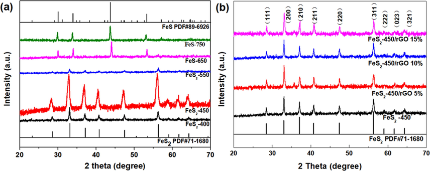
XRD patterns of prepared samples.
As reveled by SEM, the FeS2-400, FeS2-450 and FeS2-550 samples are nanospheres with the diameter ranging from 50 to 100 nm, Fig. 2a-d. Among them, the FeS2-450 exhibits more uniform dispersion and smooth surface, which can facilitate exposure of more active sites to obtain excellent OER performance, Fig. 2b-c. As the temperature increased further, the FeS-650 and FeS-750 samples present irregular micro-scale blocks, which may be caused by aggregation of catalysts, Fig. 2e-f.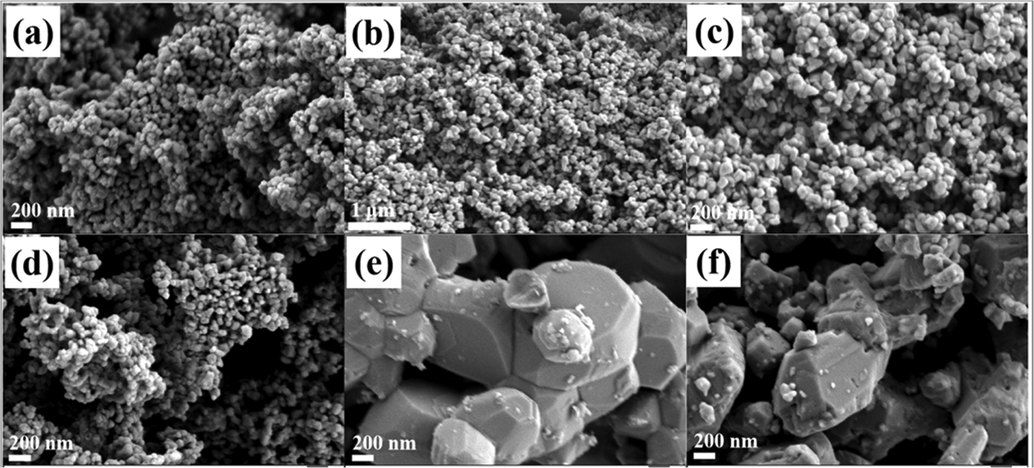
The SEM images of prepared (a) FeS2-400 (b,c) FeS2-450 (d) FeS2-550 (e) FeS-650 (f) FeS-750.
3.2 Electrocatalytic performance for OER
The electrocatalytic OER activities of Ni foam, RuO2, FeS2-400, FeS2-450, FeS2-550, FeS-650 and FeS-750 catalysts were carried out using 1 M KOH as electrolyte (pH = 11.83) at room temperature. The LSV curves show that FeS2-450 exhibits superior OER performance with smaller potentials and larger current density, indicating the excellent conductivity, as displayed in Fig. 3a. The overpotentials of the Ni foam, RuO2, FeS2-400, FeS2-450, FeS2-550, FeS-650 and FeS-750 catalysts at 10 mA/cm2 are 365 mV, 340 mV, 291 mV, 253 mV, 298 mV, 305 mV and 307 mV, respectively, Fig. 3b. Remarkably, the overpotential of FeS2-450 largely reduced to 253 mV. Further, the overpotentials of the FeS2-450 at 50 mA/cm2 and 100 mA/cm2 are 315 mV and 369 mV, respectively, even superior to commercial precious metal electrocatalyst RuO2, suggesting the outstanding OER performance. To get insight into understand the intrinsic activity, we calculated the turnover frequency (TOF) of the FeS2-450, FeS-750 and RuO2 catalysts at the overpotential of 369 mV and relevant calculation process is provided in the supporting information (Rebekah et al., 2020; Suen et al., 2017). The TOF of the FeS2-450 reaches 0.311 O2 per s per site, greater than FeS-750 (0.0114) and RuO2 (0.0071), demonstrating the highest intrinsic activity in FeS2-450. All the above results suggest that FeS2-450 exhibits the best electrocatalytic OER activity in 1 M KOH among these catalysts.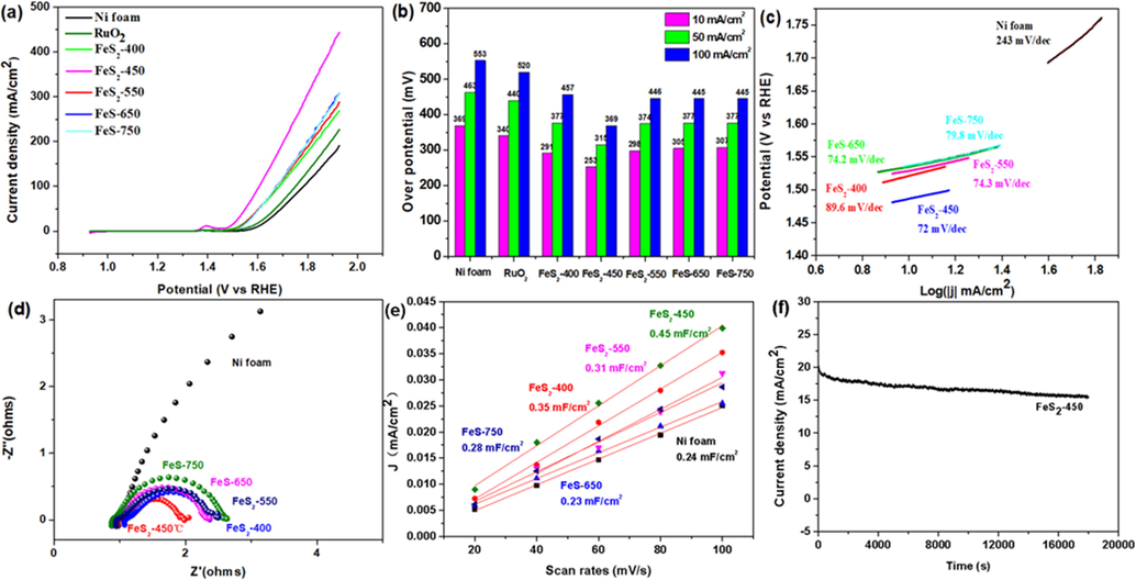
OER measurement. (a) LSV (b) the overpotentials to achieve current densities of 10, 50, and 100 mA cm−2 (c) Tafel plots, (d) Nyquist plots (e) electrochemical double-layer capacitance (Cdl) of the prepared Ni foam, FeS2-400/NF, FeS2-450/NF, FeS2-550/NF, FeS-650/NF and FeS-750/NF and (f) i-t cures of FeS2-450 sample under a constant potential of 1.527 V vs. RHE.
Tafel plots, as a common descriptors to reflect the reaction kinetic of OER, are calculated by the linear formula of η = b log|j| + a, Fig. 3c. The Tafel plot of the FeS2-450 is 72 mV/dec, which is lower than those of Ni foam (243 mV/dec), FeS2-400 (89.6 mV/dec), FeS2-550 (74.3 mV/dec), FeS-650 (74.2 mV/dec) and FeS-750 (79.8 mV/dec) catalysts, proving the remarkable OER catalytic kinetics over FeS2-450. The charge-transfer resistance (Rct) at the catalyst/electrolyte interface are further conducted by the Nyquist plots analysis, Fig. 3d. The decreased order of Rct is FeS2-450 < FeS2-400 < FeS2-550 < FeS-650 < FeS-750, demonstrating accelerated charge-transfer on highly conductive FeS2-450 (Liu et al., 2019; Li et al., 2021).
The electrochemically active areas (ECSA) are positively correlated to the electric double-layer capacitance (Cdl), which can be calculated by the CV curves at different scan rates. The CV curves of Ni-foam, FeS2-400, FeS2-450, FeS2-550, FeS-650 and FeS-750 catalysts were measured in the non-Faraday region at scan rates of 20 mVs−1, 40 mVs−1, 60 mVs−1, 80 mVs−1 and 100 mVs−1, Fig. S2. Apparently, the Cdl value for FeS2-450 is 0.45 mFcm−2, significantly larger than that of control catalysts, suggesting uniform nanoparticles dispersion of FeS2-450 offer much more accessible active sites on the surface, Fig. 3e (Shi et al., 2020). The electrochemical OER stability of FeS2-450 was tested at 1.527 V vs RHE in 1 M KOH by chronoamperometry, Fig. 3f. Apparently, FeS2-450 kept high OER stability within 5 h and without an appreciable current attenuation.
To further enhance the electrocatalytic performance of OER, rGO with high conductivity was introduced to prepared novel FeS2-450/rGO-x% electrocatalysts. The XRD patterns of FeS2-450/rGO-x% (x = 5, 10 and 15) samples are displayed in Fig. 1b and corresponding diffraction peaks index to FeS2, consistent with fabricated FeS2 at the same calcination temperature. The morphology and microstructure of the FeS2-450/rGO-10% catalyst was characterized by the SEM, TEM and HRTEM. The SEM indicates that the FeS2-450/rGO-10% is composed of FeS2-450 nanoparticles and rGO nanosheets and FeS2-450 nanoparticles are relatively uniformly dispersed on the surface of rGO nanosheets by zoom-in SEM image, Fig. 4a-c. The elemental mapping images reveals Fe and S elements are homogeneously distributed, while the elemental mapping image of exposed trace C further confirms that rGO has been surrounded by the FeS2, which is conducive to accelerate electron transfer and improve catalytic activity, Fig. 4d. TEM images of FeS2-450/rGO-10% verified that the catalyst is composed of nanoparticle and nanosheets, Fig. 4e-f. Moreover, the FeS2-450 in FeS2-450/rGO-10% has a clear surface and the lattice fringes with plane distances of 0.280 nm are assigned to (2 0 0) interplanar spacing of FeS2, Fig. 4g-h.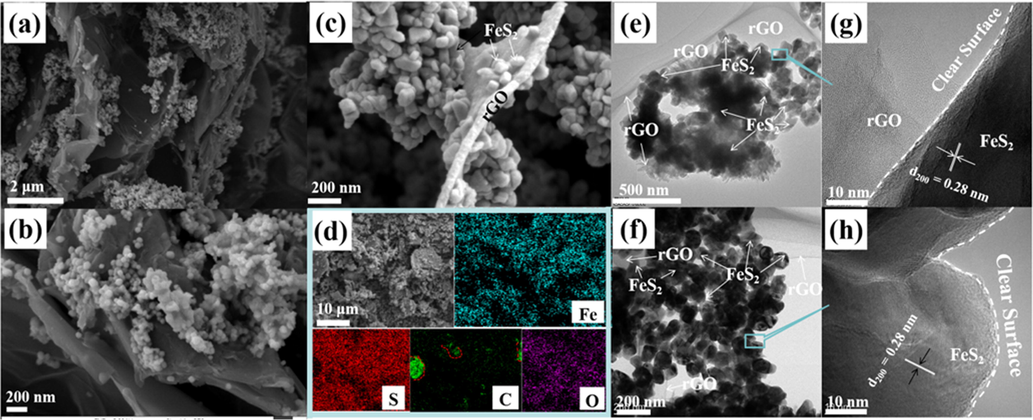
(a-c) SEM images, (d) EDX surface mapping scans, (e, f) TEM and (g, h) HRTEM images of the prepared FeS2-450/rGO-10% sample.
The OER activity of the FeS2-450/rGO-5%, FeS2-450/rGO-10% and FeS2-450/rGO-15% catalysts were also evaluated by LSV using 1.0 M KOH electrolyte and the corresponding overpotentials were displayed in Fig. 5a, b, with Ni foam, RuO2 and FeS2-450 as the contrast. Remarkably, the overpotentials of FeS2-450/rGO-10% at current density of 10 mA/cm2, 50 mA/cm2, and 100 mA/cm2 are 140 mV, 310 mV and 370 mV, respectively, significantly lower than the commercial RuO2, FeS2-450 and previous Fe/S-based catalysts toward OER in Table 1, indicating the outstanding OER performance after introducing highly conductive rGO. Compared with FeS2-450 (73 mV/dec), FeS2-450/rGO-10% showed a lower Tafel slope (71 mV/dec), demonstrating that the rGO accelerate the reaction kinetics, Fig. 5c. The The order of Rct values is FeS2-450/rGO-10% < FeS2-450/rGO-15% < FeS2-450 < FeS2-450/rGO-5% < RuO2 < Ni foam, indicating that FeS2-450/rGO-10% has the minimum charge transfer resistance for OER, Fig. 5d. Moreover, the CV curves of Ni-foam, FeS2-450, FeS2-450/rGO-5%, FeS2-450/rGO-10% and FeS2-450/rGO-15% catalysts in the non-Faraday region at different scan rates (20 mVs−1, 40 mVs−1, 60 mVs−1, 80 mVs−1 and 100 mVs−1) were presented in Fig. S3. FeS2-450/rGO-10% achieved the maximum Cdl value of 1.71 mF cm−2, which could be assigned to enhanced electron transport between the active sites and the electrolyte owing to the importing of rGO, Fig. 5e. The i-t curve in Fig. 5f shows that FeS2-450/rGO-10% catalyst kept OER stability within 5 h without an appreciable current attenuation and the current density is higher than that of FeS2-450 in Fig. 3f.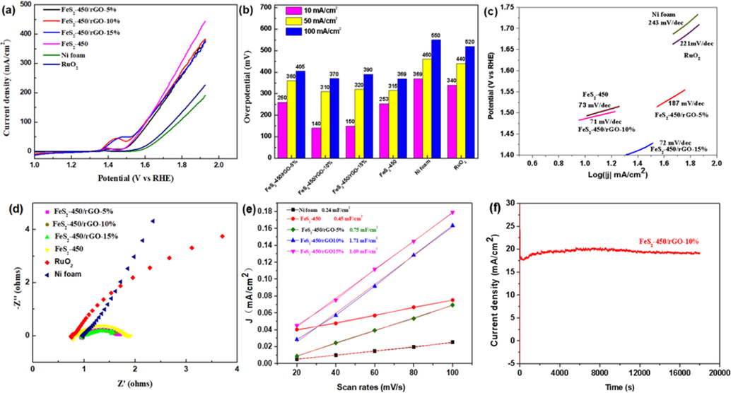
OER measurement. (a) LSV, (b) the overpotentials to achieve current densities of 10, 50, and 100 mA cm−2, (c) Tafel plots, (d) Nyquist plots (e) electrochemical double-layer capacitance (Cdl) of the prepared Ni foam, FeS2-450/NF, FeS2-450/rGO-5%/NF, FeS2-450/rGO-10%/NF and FeS2-450/rGO-15%/NF and (f) I-t curve of FeS2-450/rGO-10% under a constant potential of 1.527 V vs. RHE.
Catalysts
Electrolyte
η/mV10 mA cm−2
Tafel slope/mV dec-1
References
FeS2/C
1 M KOH
291
65.6
Pan et al., 2019
Fe7S8
1 M KOH
270
43
Chen et al., 2017
Fe7S8/FeS2/C-20
1 M KOH
262
48
Li et al., 2018a
FeNi2S4
1 M KOH
405
126
Jiang et al., 2021
Pyrite FeS2/C
1 M KOH
240
92
Li et al., 2018b
FeS2
1 M KOH
189.5
71
Wang et al., 2021
Fe0.8Ni0.15S1.05
1 M KOH
228
53
Jing et al., 2020
Ni0.7Fe0.3S2
1 M KOH
198
109
Yu et al., 2017
FeS2/CoNiSe2
1 M KOH
230
54
Yang et al., 2022
FeS2-450/rGO-10%
1 M KOH
140
71
This work
As discussed above, the FeS2-450/rGO-10% presents superior electrocatalytic performance toward OER. Meanwhile, an electrolyzer in a two-electrode FeS2-450/rGO-10%/NF//Pt/C/NF was assembled in 1 M KOH for the overall water splitting, while the RuO2/NF//Pt/C/NF and Ni foam//Ni foam system as the comparison. As expected in Fig. 6a and b, the voltage at 10 mA cm−2 for the FeS2-450/rGO-10%/NF//Pt/C/NF system is 1.52 V, significantly better than those of RuO2/NF//Pt/C/NF (1.55 V) and Ni foam//Ni foam (1.86 V) systems, indicating that the FeS2-450/rGO-10%/NF//Pt/C/NF system possess higher electrocatalytic activity toward overall water splitting.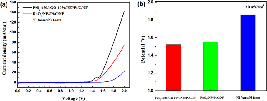
(a) LSV curves of FeS2-450/rGO-10%/NF//Pt/C/NF, RuO2/NF//Pt/C/NF and Ni foam//Ni foam and (b) the corresponding potential at current densities of 10 mA cm−2 under a constant potential of 1.6 V.
3.3 Characterization after OER
To get insight to understand the OER catalytic activity and stability, a systematic investigation of the catalyst after OER was conducted. The FeS2-450/rGO-10% catalyst after stability test maintain nanoparticles and nanosheets morphology, Fig. 7a-e, demonstrating its high stability. Moreover, the elemental mapping of catalysts after OER in Fig. 7c indicates the uniform distribution of Fe, S, C, and O elements. It is worth noting that the clear surface of catalyst disappeared considerably, although lattice fringes with plane distances of 0.280 nm is also assigned to (2 0 0) interplanar spacing of FeS2. At the same time, an amorphous layer with some defects appeared, which may be associated with Fe oxo/hydroxide species or S defects, implying the surface reconstruction of the catalyst.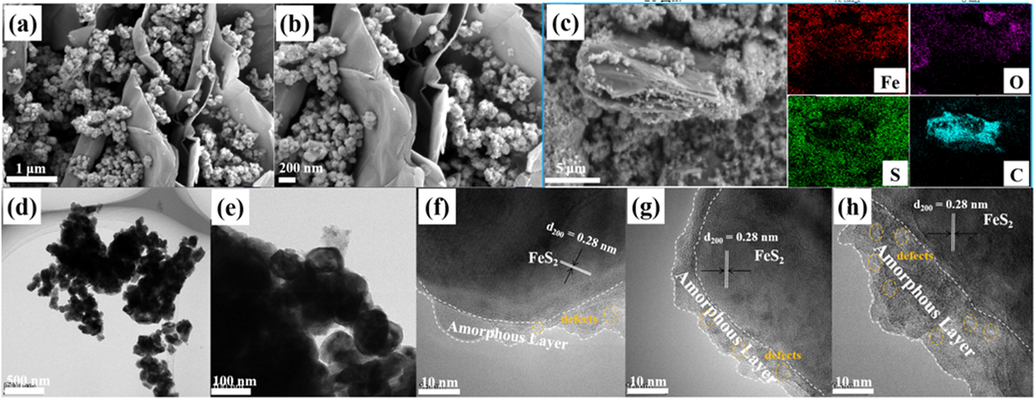
(a, b) SEM images, (c) EDX surface mapping scans, (d, e) TEM and (f-h) HRTEM images of the prepared FeS2-450/rGO-10% after OER.
To figure out the structure and electronic structure of the catalyst before and after stability test, we have performed a series of studies, Fig. 8. First, the chemical state of the catalyst before and after the reaction was investigated through XPS. The full spectrum in Fig. 8a suggests the coexistence of Fe 2p, S 2p, O 1s and C 1s elements. The binding energies at 707.5 eV and 720.3 eV assigned to the Fe(II)-S 2p3/2 and Fe(II)-S 2p1/2 while the other two peaks at 712.3 eV and 725.9 eV belong to the Fe3+(Chen et al., 2022), and the latter could be assigned to Fe-OOH bonds, Fig. 8b. The peaks intensity and area of Fe3+ after OER is dramatically stronger and larger compared to catalyst before the reaction, indicating the formation of Fe-oxo/hydroxide species during the catalytic process (Yu et al., 2017), Fig. 8b. The binding energies at 163.0 eV and 164. eV can ascribe to S 2p3/2 and S 2p1/2 in metal sulfide, while the two peaks at 168.4 eV and 169.7 eV belong to sulfate (Wang et al., 2017), resulting from particle oxidation of FeS2, Fig. 8c. The peak at 529.8 eV belonging to O2– (lattice O) after OER became more vigorous, which is consistent with the increased peak of Fe-OOH bonds, further confirming the existence of Fe-oxo/hydroxide species and surface reconstruction of the catalyst, Fig. 8d.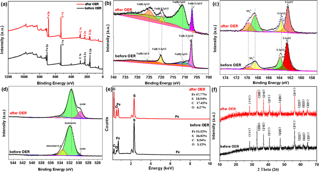
XPS spectra of (a) survey (b) Fe 2p (c) S 2p (d) O 2p (e) the percentages of Fe, S, C and O with the prepared FeS2-450/rGO-10% before and after OER and (f) XRD with the prepared FeS2-450/rGO-10% before and after OER.
On the other hand, the comparison of EDX elemental analysis before and after the reaction clearly shows that the S relative content sharply reduced, in Fig. 8e. In contrast, the O content increased after OER, further verifying the surface reconstruction of catalysts, which is consistent with the above discussion in XPS. In addition, XRD was used to characterize the phase composites of the catalysts before and after OER. No significant difference was found in FeS2-450/rGO-10% after OER compared with that of before OER, suggesting that the FeS2 in FeS2-450/rGO-10% catalyst kept its phase and the reconstruction of the catalyst only occurred on the surface, Fig. 8f.
4 Conclusion
Thanks to the integration of FeS2 and highly conductive rGO, the FeS2-450/rGO-10% exhibited the best catalytic activity toward OER with an ultra-low overpotential of 140 mV and a smaller Tafel slope of 71 mV/dec and better stability than FeS2-450 and commercial RuO2. As discussed above, the enhanced catalytic activity originated from the synergistic effect of surface reconstruction of FeS2 and rGO, in which the surface of FeS2 functions as catalytic active sites because of the reconstruction of the structure and chemical state and rGO serves as effective electron transfer channel at the catalyst/electrolyte interface. This facile synthetic strategy of excellent electrocatalytic performance for OER toward overall water splitting opens new avenues for potential practical application.
CRediT authorship contribution statement
Xiaozhen Ren: Conceptualization, Methodology, Writing - original draft, Writing - review & editing, Supervision. Hua Yang: Conceptualization, Methodology, Writing - review & editing, Supervision.
Acknowledgements
This work was supported by the Natural Science Foundation of Shandong Province (ZR2021QE086) and the Undergraduate Innovation Training Program Fund of Liaocheng University (Grant No. cxcy2022247).
Declaration of Competing Interest
The authors declare that they have no known competing financial interests or personal relationships that could have appeared to influence the work reported in this paper.
References
- IrO2 coated on RuO2 as efficient and stable electroactive nanocatalysts for electrochemical water splitting. J. Phys. Chem. C.. 2016;120(5):2562-2573.
- [CrossRef] [Google Scholar]
- Highly active Fe sites in ultrathin pyrrhotite Fe7S8 nanosheets realizing efficient electrocatalytic oxygen evolution. ACS Cent. Sci.. 2017;3(11):1221-1227.
- [CrossRef] [Google Scholar]
- Trimetallic oxyhydroxides as active sites for large-current-density alkaline oxygen evolution and overall water splitting. J. Mater. Sci. Technol.. 2022;110:128.
- [CrossRef] [Google Scholar]
- Direct observation of structural evolution of metal chalcogenide in electrocatalytic water oxidation. ACS Nano. 2018;12(12):12369.
- [CrossRef] [Google Scholar]
- Efficient water oxidation using nanostructured α-Nickel-hydrixide as an electrocatalyst. J. Am. Chem. Soc.. 2014;136(19):7077-7084.
- [CrossRef] [Google Scholar]
- Nanostructured metallic FeNi2S4 with reconstruction to generate FeNi-based oxide as a highly-efficient oxygen evolution electrocatalyst. Nano Energy. 2021;81:105619
- [CrossRef] [Google Scholar]
- Hydrated Manganese(II) Phosphate (Mn3(PO4)2·3(H2O) as a water oxidation catalyst. J. Am. Chem. Soc.. 2014;136:7435-7443.
- [CrossRef] [Google Scholar]
- Nickel-doped pyrrhotite iron sulfide nanosheets as a highly efficient electrocatalyst for water splitting. J. Mater. Chem. A.. 2020;8:20323-20330.
- [CrossRef] [Google Scholar]
- Synergistic interface engineering and structural optimization of non-noble metal telluride-nitride electrocatalysts for sustainably overall seawater electrolysis. Appl. Catal. B: Environ.. 2022;318:121834
- [CrossRef] [Google Scholar]
- Pyrite FeS2/C nanoparticles as an efficient bi-functional catalyst for overall water splitting. Dalton Trans.. 2018;47:14917-14923.
- [CrossRef] [Google Scholar]
- FeS2/CoS2 interface nanosheets as efficient bifunctional electrocatalyst for overall water splitting. Small. 2018;14:1801070.
- [CrossRef] [Google Scholar]
- Interface engineering of transitional metal sulfide–MoS2 heterostructure composites as effective electrocatalysts for water-splitting. J. Mater. Chem. A. 2021;9:2070-2092.
- [CrossRef] [Google Scholar]
- Interface engineering of (Ni, Fe)S2@MoS2 heterostructures for synergetic electrochemical water splitting. Appl. Catal. B: Environ.. 2019;247:107-114.
- [CrossRef] [Google Scholar]
- FeS2/C nanowires as an effective catalyst for oxygen evolution reaction by electrolytic water splitting. Materials. 2019;12(20):3364.
- [CrossRef] [Google Scholar]
- Zn-substituted MnCo2O4 nanostructure anchored over rGO for boosting the electrocatalytic performance towards methanol oxidation and oxygen evolution reaction (OER) Int. J. Hydrogen Energy.. 2020;45(29):14713-14727.
- [CrossRef] [Google Scholar]
- FeNiS2/reduced graphene oxide electrocatalysis with reconstruction to generate FeNi oxo/hydroxide as a highly-efficient water oxidation electrocatalyst. Rare Metals. 2022;41(12):4127-4137.
- [CrossRef] [Google Scholar]
- Mechanistic insights into the promotional effect of Ni substitution in non-noble metal carbides for highly enhanced water splitting. Appl. Catal. B: Environ.. 2021;298:120560
- [CrossRef] [Google Scholar]
- A flower-like CoS2/MoS2 heteronanosheet array as an active and stable electrocatalyst toward the hydrogen evolution reaction in alkaline media. RSC Adv.. 2020;10:8973-8981.
- [CrossRef] [Google Scholar]
- Electrocatalysis for the oxygen evolution reaction: recent development and future perspectives. Chem. Soc. Rev.. 2017;46:337-365.
- [CrossRef] [Google Scholar]
- Intercalated Co(OH)2-derived flower-like hybrids composed of cobalt sulfifide nanoparticles partially embedded in nitrogendoped carbon nanosheets with superior lithium storage. J. Mater. Chem.. 2017;5:3628-3637.
- [CrossRef] [Google Scholar]
- Intensified Kirkendall effect assisted construction of double-shell hollow Cu-doped CoP nanoparticles anchored by carbon arrays for water splitting. Appl. Catal. B: Environ.. 2023;325:122295
- [CrossRef] [Google Scholar]
- Surface self-reconstructed amorphous/crystalline hybrid iron disulfifide for high-effiffifficiency water oxidation electrocatalysis. Dalton Trans.. 2021;50:6333-6342.
- [CrossRef] [Google Scholar]
- High-performance bifunctional oxygen electrocatalyst derived from iron and nickel substituted perfluorosulfonic acid/polytetrafluoroethylene copolymer. Nano Energy. 2016;30:801-809.
- [CrossRef] [Google Scholar]
- Modulating interband energy separation of boron-doped Fe7S8/FeS2 electrocatalysts to boost alkaline hydrogen evolution reaction. Adv. Funct. Mater.. 2022;32:2107802.
- [CrossRef] [Google Scholar]
- Fe7S8/FeS2/C as an efficient catalyst for electrocatalytic water splitting. Int. J. Hydrogen Energy.. 2021;46:39216-39225.
- [CrossRef] [Google Scholar]
- Metal-organic framework-derived FeS2/CoNiSe2 heterostructure nanosheets for highly-efficient oxygen evolution reaction. Appl. Surf. Sci.. 2022;578:152016
- [CrossRef] [Google Scholar]
- Ternary nickel-iron sulfide microflowers as a robust electrocatalyst for bifunctional water splitting. J. Mater. Chem. A. 2017;5:15838-15844.
- [CrossRef] [Google Scholar]
Appendix A
Supplementary material
Supplementary data to this article can be found online at https://doi.org/10.1016/j.arabjc.2023.105069.
Appendix A
Supplementary material
The following are the Supplementary data to this article:Supplementary data 1
Supplementary data 1


