

Translate this page into:
Hydrogen production via catalytic methane decomposition over alumina supported iron catalyst
⁎Corresponding author. Fax: +966 1 4678770. aalfatesh@ksu.edu.sa (Ahmed S. Al-Fatesh)
-
Received: ,
Accepted: ,
This article was originally published by Elsevier and was migrated to Scientific Scholar after the change of Publisher.
Peer review under responsibility of King Saud University.
Abstract
In this paper, iron-based catalysts, calcined at different temperatures (300–800 °C), supported over alumina, were investigated for hydrogen production via catalytic methane decomposition. The catalysts were prepared by using different methods such as impregnation and co-precipitation. The fresh and spent catalysts were characterized using different techniques such as Brunauer, Emmett and Teller (BET), temperature-programmed reduction by hydrogen (H2-TPR), X-ray powder diffraction (XRD), thermogravimetry analysis (TGA), Field Emission Scanning Electron Microscope (FESEM) and transmission electron microscopy (TEM). Results revealed that for both impregnated and co-precipitated catalysts, calcination temperature of 500 °C is optimal. Type of precursor iron oxide on the alumina support has a strong influence on its performance for methane decomposition.
Keywords
Decomposition
Methane
Hydrogen
Iron catalyst

1 Introduction
Renewable energy technologies are gaining considerable attention to contribute positively to the economic development and to overcome the shortage of energy supply and the problem of global warming due to excessive use of fossil fuels that emit greenhouse gases (Varbanov, 2014; Menash, 2014; Klemeš et al., 2010). Stringent regulations and penalties placed on companies which discharge waste and greenhouse gas emissions (Al-Fatesh and Fakeeha, 2012; Mandelli et al., 2014) facilitate this trend. In this scenario, production of an environmentally benign energy carrier such as hydrogen can play a substantial role in the procurement of sustainable energy (Balat, 2008; Muradov and Veziroglu, 2008; Ashok et al., 2008). About 96% of all hydrogen is derived from fossil feed stocks, e.g., with natural gas 49%, liquid hydrocarbons 29%, and coal 18%. Electrolysis and other by-product sources account for the rest 4%. Future for hydrogen looks strong in the coming years with an estimated consumption ∼800 billion cubic meters in 2018 (http://chemical.ihs.com/CEH/Public/Reports/743.5000, 2014). Currently, syngas/hydrogen is mostly produced by steam reforming of natural gas and other fossil feed stocks. Subsequent Water Gas Shift maximizes hydrogen yields. However, the disadvantages of this route are lower efficiency (∼75%), huge emission of greenhouse gases and air pollution resulting from the generation of CO2 (Baschuk and Li, 2001; Choudhary and Goodman, 2002; Sun et al., 2005; Mondal et al., 2015; Talkhoncheh and Haghighi, 2015; Diehm and Deutschmann, 2014).
In this context, catalytic methane decomposition (CMD) is a worthwhile approach for production of pure hydrogen and valuable carbon (Lua and Wang, 2013; Amin et al., 2011; Abbas and Daud, 2010; Al-Fatesh and Fakeeha, 2012; Navarro and Pena, 2007; Torres et al., 2014). The solid carbon formed, depending upon its nature, type and properties can be used in different applications, which in turn can favor the economy of the process (Otsuka et al., 2004). For instance, the by-product carbon can be used in carbon fuel cells (Li et al., 2011). In addition to traditional amorphous and graphitic carbons, carbon nanotubes and nanofibers or even other allotropic forms of carbon such as graphene structures can also be obtained during methane pyrolysis (Jana et al., 2011). The graphitic carbon nanofibers have unique and attractive properties; for example, they possess strong resistance to strong acids and bases, and have high electrical conductivity, surface area, good mechanical strength and tunable surface properties for use as catalyst support (Edwards et al., 2008; Mahlia and Chan, 2011).
Transition metals such as Fe, Ni, Co are often used for catalytic methane decomposition because of their tendency for carbide formation. To enhance the activity and the stability of the active metal, catalyst is structurally promoted (Avdeeva et al., 1996) e.g., alumina supported catalysts have shown excellent activity and stability for alkane pyrolysis, as reported by many investigators (Li et al., 1997; Awadallah et al., 2014; Gandhi and Mo, 2014). The overall performance of the (CMD) catalysts depends on parameters such as preparation route, the type of active metal, its structure and support used (Jiang et al., 2003). Fe based catalysts were reported to be efficient for the catalytic methane decomposition (Pudukudy and Yaakob, 2015; Pudukudy et al., 2015; Jin et al., 2013; Torres et al., 2012). Pudukudy and Yaakob studied methane decomposition over Ni, Co and Fe based monometallic catalysts supported on sol gel derived SiO2 micro-flakes and reported superior stability of Fe based catalyst (Pudukudy and Yaakob, 2015). Yeoh et al. (2013) investigated the influence of calcination temperature on Ni, Co or Fe supported on silica in order to understand influence, if any, of the metal support interaction in the resulting catalyst. Experimental results showed that the calcination temperature affected carbon yield, size (diameter) and the quality of the CNTs.
Typically, for iron-based catalysts, calcination of iron precursors leads to a variety of iron oxides. These can include, depending on calcination temperature, magnetite (Fe3O4), maghemite, (γ-Fe2O3−x), wustite (FeO), hematite (α-Fe2O3) and/or spinel structures (AB2O4) formed between iron and support oxides. Fe in cationic form (Fe2+, or Fe3+) is present in octahedral or tetrahedral oxygen environments in these oxides. During pre-reduction treatments as well as the high temperature methane pyrolysis, hydrogen present in the reaction environment would reduce the iron oxides, in situ, to partially reduce Fe oxide or Fe metal. Recently, Guo et al., (2014) reported the importance of the nature and structural environment of Fe on the pyrolysis decomposition of methane. They claimed that a single Fe atom present in the silica matrix to be the active catalytic species.
In this work, catalytic decomposition of methane over alumina supported iron catalyst is reported. The influence of preparation procedures such as (i) method of metal incorporation (impregnation vs adsorption) and (ii) pretreatment (ex situ calcination and in situ reduction) on the performance of the catalysts was studied. Characteristic details of the catalysts and their relation to performance are discussed.
2 Experimental
2.1 Catalyst preparation
Supported 20 wt.% Fe catalysts used in this study were prepared by incipient wet-impregnation or co-precipitating method. All chemicals used were of analytical grade (BDH Chemical Sigma-Aldrich®). Pellets of alumina (γ-Al2O3; SA6175 – Norton®) were crushed to fine grains (200 μm) before use.
In the case of wet-impregnation, required amount of [Fe(NO3)3·9H2O] dissolved in double-distilled water, was brought in contact with γ-Al2O3 under constant stirring at 80 °C for 3 h. The catalysts were then dried at 120 °C for 12 h and calcined at 300, 400, 500 or 800 °C, in air for 3 h. In the case co-precipitation, stoichiometric amounts of the precursors of the active metal [Fe(NO3)2·9H2O] and that of the support [Al(NO3)3·9H2O] were dissolved in distilled water under constant stirring at 60 °C and 10 vol.% aqueous NH3 solution was added dropwise until pH 9 was reached. Precipitates were filtered, washed with deionized water and acetone, dried at 120 °C for 12 h and finally calcined similarly as described above.
2.2 Catalyst characterization
The specific surface areas of the catalysts were determined by the BET method using a Micromeritics Tristar II 3020 surface area and porosity analyzer. For each analysis, 0.2–0.3 g of catalyst was degassed at 300 °C for 3 h before measurement. Temperature Programmed Reduction (TPR) measurements were completed on Micromeritics Auto Chem II using 70 mg samples. Samples were pre-heated in Argon (99.9%) at 150 °C for 30 min, followed by cooling to room temperature and then heating to 1000 °C at 10 °C/min using a 10% H2/Ar, 40 mL/min. H2 consumption was monitored by a thermal conductivity detector (TCD). The quantitative analysis of coke deposition on the spent catalysts was carried out by thermo-gravimetric analysis (TGA) in air (30 mL min−1) using EXSTAR SII TG/DTA 7300 analyzer. 10–15 mg of the used catalyst was heated from room temperature to 800 °C at a heating rate of 20 °C/min.
The crystalline structure of prepared samples was characterized with powder X-ray diffraction (XRD) on a Bruker D8 Advance X-ray diffractometer equipped with Cu Kα radiation source operated at 40 kV and 40 mA. The scanning step size and range of 2θ for analysis were 0.01° and 10–85° respectively. The phases present were identified with the help of standard powder XRD cards (JCPDS).
2.3 Catalyst testing
Methane decomposition reaction was carried out at atmospheric pressure in a tubular (9.1 mm i.d. and 30 cm long, stainless steel) fixed-bed continuous-flow micro-reactor (PID, Micromeritics) using 0.3 g of the catalyst. The reactor assembly contains single heating zone furnace; the reaction temperature was measured using a K-type thermocouple placed axially and centered in the catalyst bed. The operating gas hourly space velocity was 5000 mL h−1 gcat−1. The reactant gas comprised CH4 and N2 in the ratio of 1.5:1. Prior to reaction, the catalyst was subjected to reduction at 700 °C using hydrogen gas at a flow rate of 40 mL/min for 90 min. The catalytic activity was studied at 700 °C and 800 °C. The effluent gases were analyzed by an online GC (Shimadzu GC-2014) using a PP-Q column and a TCD detector. CH4 conversion and hydrogen yields were calculated using the GC data.
3 Results and discussions
3.1 Catalyst characterization
The catalyst pretreatment is considered to be among the most effective means to bring catalyst to the required state. Consequently, calcination and activation (pre-reduction, in situ reduction) are expected to influence the performance for catalytic decomposition of methane (CDM). During drying after impregnation, the active metal precursor solution taken by the porous support may migrate by capillary flow and/or diffusion and the solute particles (active metal precursor) are redistributed on the support alumina. Furthermore, as the solvent evaporates, precipitation of solute happens as the solution becomes supersaturated and brings crystallization of the precursors within the pores and the outer surface of the support material. During calcination oxide precursors are formed, which can undergo solid state transformations, reactions with support oxide as well as sintering of various phases (Hagen, 2006; Al-Fatesh and Fakeeha, 2012). In the present case, to investigate the effect of calcination temperature, experiments have been carried out in which the temperature was varied between 300 and 800 °C and the so prepared catalysts were tested for CDM. Characteristics of the catalysts are reported first, followed by the results of catalyst testing.
Table S1 summarizes the results of the textural characterization of the two catalysts series (i.e., 20Fe-Al-CP, 20Fe-Al-Imp) before and after reaction. As expected, increase in calcination temperature caused substantial changes in the textural properties. For instance, at 300 °C calcination temperature, the 20Fe-Al-CP, 20Fe-AL-Imp catalysts showed 301.9 m2/g, and 209.4 m2/g BET surface area, which decreased to 104.1 m2/g, and 93.5 m2/g respectively at 800 °C calcination. Fig. S1a and b presents the results of N2 sorption isotherms for the two sets of catalysts, i.e., 20Fe-Al-CP and 20Fe-Al-Imp), respectively. According to the IUPAC classification, the observed adsorption-desorption isotherms are identical to type IV isotherms; however, with differently shaped hysteresis loops. In the case of 20Fe-Al-CP catalyst series the hysteresis loops are of type H3, whereas in the case of 20Fe-Al-Imp catalyst series these are of type H2. The main effect of catalyst calcination is the loss of surface area, and change of pore shapes; however, the changes in pore volumes are only marginal. Interestingly, even after calcination at 800 °C the catalysts still retain a high surface area, >90 m2 g−1.
Table S1 also presents the textural properties of 20Fe-Al-CP and 20Fe-Al-Imp catalyst series after methane decomposition reaction. It is interesting to note that for 20Fe-Al-CP catalyst series, all catalysts showed a decrease in surface area as compared to fresh catalyst surface area except catalyst calcined at 800 °C which exhibited more surface area after reaction which might be associated with carbon being produced contributing to increased surface area of this catalyst. Similar trend was observed for 20Fe-Al-Imp catalyst series as well.
To study the reducibility of the fresh catalyst temperature programmed reduction (TPR) experiments were performed. The H2-TPR profiles for the selected samples of alumina and supported catalysts, calcined at different temperatures, are presented in Figs. 1a and 1b, respectively. It is evident from results that, in general, for all catalysts more than one well differentiated reduction peak are observed, indicating that these catalysts go through stepwise multiple reduction stages. Indeed, this is a common feature of Fe based catalysts, where, as discussed in the beginning, a variety of oxide phases are possible (Jozwiak et al., 2007).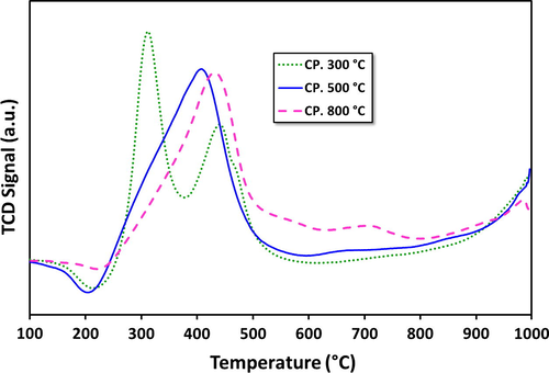
H2-TPR patterns for fresh 20Fe-Al-CP catalyst series at different calcination temperatures.
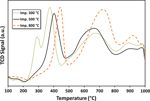
H2-TPR patterns for fresh 20Fe-Al-Imp catalysts calcined at different temperatures.
Alumina supported catalysts, prepared by different routes, the 20Fe-Al-CP (Fig. 1a) and 20Fe-Al-Imp (Fig. 1b) exhibited quite different reduction patterns. Generally, for the catalysts prepared via impregnation, three reduction peaks were observed. On the other hand, the 20Fe-Al-CP series showed one to two reduction peaks, in their respective TPR profiles (Fig 1a). In general the first H2 consumption peaks centered at temperatures <500 °C are attributed to the reduction of bulk hematite species to magnetite (i.e., α-Fe2O3 → Fe3O4) (Pinilla et al., 2011). Magnetite is a spinel where Fe is in both 2+ and 3+ oxidation states, unlike hematite which has only Fe3+. The second reduction centered around 500–800 °C represents the further reduction of magnetite to metallic iron (Fe3O4 → α-Fe) (Pinilla et al., 2011). In addition, the third segment with high temperature (>800 °C) H2 consumption peaks is attributed to the reduction of mixed spinel-structure mixed oxide species such as Fe(III) and Fe(II) aluminates (Pinilla et al., 2011). This peak is more pronounced for catalysts prepared by impregnation. Impregnation leads to enhanced local (surface) iron oxide concentrations, and this can help in the mixed oxide formation. In agreement with this, TPR of catalysts prepared by co-precipitation, shows only very small peaks in the high temperature region (700 °C), indicating minimal spinel like mixed oxide formation. Further, the catalysts prepared by co-precipitation also seem to reduce more easily at lower temperature and also in one step, probably directly from hematite. The catalyst calcined at 300 °C is an exception that there are two steps. The presence of different iron oxides can be the reason for the small shifts in peak positions among samples, and makes it difficult to point out the exact nature of the samples. Our current results are, however, consistent with the previously reported results related to the reduction of patterns for FexOy/Al2O3 catalysts (Torres et al., 2014). They also indicate that formation mixed oxides between iron oxide and alumina are possible. In the case of supported metal catalysts the metal-support interaction (MSI) plays a significant role in the reduction behavior of the metal oxide precursors as well as metal dispersion. As the strength of the MSI increases, it becomes more difficult to reduce the precursor oxide (Li et al., 2011; Abbas and Daud, 2010). MSI can well affect the crystallography as well as the electronic state of the metal particles, which in turn can influence the performance of the catalyst in the decomposition reaction. Additionally, it has been reported in the literature that graphitic nano carbon fiber formation is favored in case of weak MSI due to the fact that weak MSI allows metal particles to form carbides, detached from the support and these particles get lifted up to the tip of growing carbon nanomaterials. Conversely, strong MSI promotes base-growth mechanism for carbon production in which carbon nanomaterials grow having metal particles at their base (Lamouroux et al., 2007).
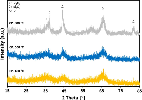
For alumina supported catalyst series, the XRD patterns after calcination at different temperatures are presented in Figs. 2a and 2b. It is evident from results that both 20Fe-Al-CP and 20Fe-Al-Imp catalyst series exhibited quite different XRD profiles. In the case of 20Fe-Al-CP (Fig. 2a), the XRD peaks were broad and alumina phase appeared as dominant at lower calcination temperatures. However, at a higher calcination temperature (800 °C) the peak related to α-Fe2O3 at 2θ = 33.4° is also observed. On the other hand, in the case of 20Fe-Al-Imp catalyst series (Fig. 2b), both alumina and α-Fe2O3 phases were clearly observed in all XRD profiles, irrespective of the calcination temperature. The following intense diffraction lines located at 2θ = 39.6°; 46° and 66.7° are related to Al2O3 support (JCPDS: 00-004-0875), whereas the peaks identified at 2θ = 24.3°, 33.4°, 35.8°, 49.8°, 54.4°, 62.4° and 64.3° are related to hematite. Moreover, for 20Fe-Al-Imp catalyst series, the diffraction peaks noticed at 2θ = 30.7°, 36.2° and 58.3° can be attributed to Fe-aluminates (JCPDS: 01-089-1694). Moreover, XRD patterns of freshly reduced catalysts are shown in Figs. 3a and 3b to estimate the phases related to active metal as well as active metal oxides after reduction. It is obvious from XRD profiles that calcination temperature also influenced the reduction behavior of catalysts and some of these catalysts, even after reduction, contained iron oxide species which affected, later on, catalytic performance. All catalysts showed diffraction patterns similar to calcined catalysts and in addition iron metal species were identified after reduction. The diffraction peaks identified at 2θ = 30.2°, 35.8° and 43° are attributed to Fe3O4 species and the diffraction patterns identified at 2θ = 44°, 65° and 82.5° are attributed to iron metal species.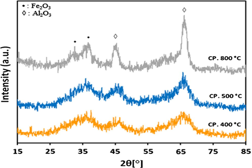
XRD patterns for 20Fe-Al-CP fresh catalysts calcined at different temperatures.
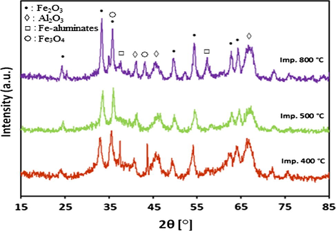
XRD patterns for 20Fe-Al-Imp fresh catalysts calcined at different temperatures.
XRD patterns for 20Fe-Al-CP fresh catalysts reduced at different temperatures.

XRD patterns for 20Fe-Al-Imp fresh catalysts reduced at different temperatures.
Fig. 4a–d presents the morphology of freshly reduced 20Fe-Al-Imp and 20Fe-Al-CP catalysts calcined and reduced at 500 °C. It can be seen from TEM results that both catalysts possess uniform metal particles distribution. Moreover, 20Fe-Al-CP comprised metal particles with size ranging from 5 to 40 nm while 20Fe-Al-Imp consisted of metal particles having size 10–50 nm.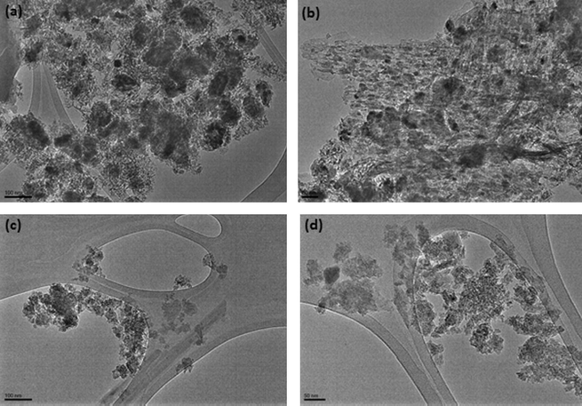
TEM images of freshly reduced (a) 20Fe-Al-Imp catalyst calcined at 500 °C; (b) 20Fe-Al-CP catalyst calcined at 500 °C.
To summarize, as a result of calcination at different temperatures, a variety of iron oxides are possibly formed. According to stoichiometry Fe is present in 3+ oxidation states predominantly in hematite and other possible Fe2O3 forms (e.g. maghemite, γ-Fe2O3−x) which cannot be differentiated with XRD (below detection limits) and TPR (overlapping reduction peaks) under our conditions. In the case of magnetite (Fe3O4) and spinel oxides (e.g., FeAl2O4) Fe can also be in 2+ oxidation state. Catalysts prepared by impregnation have also a tendency to form the mixed oxide spinel phase. Thus, both the preparation technique (Co-precipitation vs impregnation) and calcination temperature of the Fe precursor result in catalysts where Fe is in 2+ or 3+ oxidation states and further present in Oh or Td surroundings of oxygen ions.
During CDM at the 700–800 °C, catalytically active iron sites are formed by the reduction (pre-reduction of the reaction temperature as well as in situ reduction during the initial stages of the reaction by the formed hydrogen) of the different precursor Fe oxide species. Methane decomposition and the influence of, if any, on these catalysts are discussed next.
3.2 Catalytic performance evaluation
Catalytic performance, in terms of CH4 conversion and H2 yield as a function of time on stream, is presented in Figs. 5 and 6a and b for the various catalysts. In the case of 20Fe-Al-CP series, it is noticeable (Fig. 5a) that, all catalysts exhibited low CH4 conversion and also strong deactivation. The catalyst which was calcined at 500 °C was the exception. This catalyst showed an increase in activity with TOS. Since the hydrogen yields are directly related to CH4 conversion, (Fig. 5b) trends in H2 were found to be similar to CH4 conversion as a function of TOS. The highest methane conversion and hydrogen yield obtained were 50% and 45% respectively.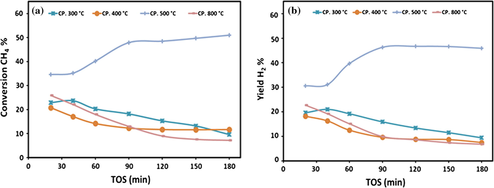
Variations of (a) CH4 conversions and (b) H2 yield over 20Fe-Al-CP catalysts series at different calcination temperatures on TOS at 700 °C.
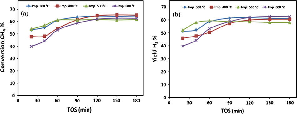
Variations of (a) CH4 conversions and (b) H2 yield over 20Fe-Al-Imp catalysts series at different calcination temperatures on TOS at 700 °C.
On the other hand, in the case of 20Fe-Al-Imp catalyst series, it is quite interesting to note that the calcination temperature has no significant effect on the catalytic performance of these catalysts. However, initially these catalysts showed some difference in CH4 activity (Fig. 6a) and H2 yield (Fig. 6b) but with TOS this difference becomes minor. Generally, all catalysts of 20Fe-Al-Imp series exhibited around 65% CH4 conversion after 90 min TOS without any deactivation. Same trends were also observed for hydrogen and 60% hydrogen yield was recorded after 90 min TOS, as expected.
To summarize, in case of 20Fe-Al-CP catalyst series, the catalysts prepared at low (i.e., 300 °C) as well as at high (i.e., 800 °C) calcination temperatures exhibited very poor performance, whereas at intermediate (i.e., 400 and 500 °C) calcination temperatures the catalysts showed reasonably better performance while 20Fe-Al-Imp catalysts exhibited excellent activity irrespective of calcination temperature. Moreover, it is also interesting to note from Figs. 5 and 6 that, at each individual calcination temperature the 20Fe-Al-Imp catalysts performed relatively better as compared to 20Fe-Al-CP catalysts. For instance, at 400 °C calcination temperature the initial values of CH4 activity and H2 yield were 47.8% and 45.9% respectively over 20Fe-Al-Imp catalyst, whereas for 20Fe-Al-CP catalysts both values were 20.8% & 18.2% respectively.
On the basis of these obtained results, we can conclude that, irrespective of calcination temperatures, the 20Fe-Al-Imp catalyst series presented overall better performance. Recall that these catalysts also had higher amounts of spinel phases where Fe is also in 2+ oxidation state. We also observed that calcination around 500 °C also led to the formation of Fe3O4 (Fe-Al-CP, 500 °C calcination). Fe3O4 (Fe3+2Fe2+O4) is also a spinel where Fe is partly present in 2+ state. Significantly, this catalyst also showed enhanced activity for methane decomposition. This leads us to speculate that Fe2+ oxide may be the optimal precursor for the formation of the active catalytic site via reduction, in situ, during methane decomposition. A detailed in situ characterization to identify the nature of the catalytic site for methane decomposition is necessary to make definite conclusions and is beyond the scope of the study.
It can be seen from Figs. 5 and 6 that methane conversion and hydrogen yield increased with TOS initially in case of 20Fe-Al-CP catalyst calcined at 500 °C while all other catalysts deactivated over time on stream. Moreover, all impregnated catalysts calcined at different temperatures also showed this increasing activity with time without deactivation. The relatively better catalytic performance of impregnated catalysts may be related to the type of oxide species present in them. It can be seen from XRD patterns of calcined and reduced catalysts as well as TPR profiles that impregnated catalysts calcined at different temperatures contain Fe metal and different Fe species, i.e., α-Fe2O3, Fe3O4 and spinel species. It has been reported in the literature that depending upon reduction temperature (TR), these reduce as per following reaction equations (Pineau et al., 2006, 2007):
Moreover, FeO is unstable below 570 °C. It can be concluded from the above discussion that impregnated catalysts reduced at 500 °C contain Fe3O4, spinel species and some Fe metal species arising from reaction 2 which can start the methane decomposition. Since FeO is unstable for TR below 570 °C, no FeO is present for catalysts reduced at 500 °C. Moreover impregnated catalysts reduced at 700 °C possess FeO and spinel species resulting from reaction (3). It can be seen from activity curves that conversion and yield increase with time until these become stable. It can be associated with an in-situ reduction of Fe3O4 in case of catalysts reduced at 500 °C and reduction of FeO for catalyst reduced at 700 °C. Furthermore, the metal particle size can also play a role in the activity. Co-precipitated catalysts contain smaller metal particles having diameter around 5 nm while larger particles were formed in catalysts prepared by impregnation (Fig. 4). It is interesting to note that co-precipitated catalysts do not have spinel or the higher temperature FeO species in TPR profiles following reaction 1. Smaller particles in co-precipitated catalysts may be responsible for the absence of FeO species in TPR profiles of co-precipitated catalysts. XRD patterns of reduced catalysts (Fig. 3) support the above arguments as well.
The results of effect of reaction temperature on CH4 conversion and H2 yield over 20Fe-Al-Imp catalyst, at different calcination temperature, are presented in Fig. 7a and b, respectively. The results revealed that, regardless of the calcination temperature, both CH4 conversion and H2 yield increased with the reaction temperature and reached close to 80% conversion of methane and hydrogen yield about also 80%. All samples showed their highest catalytic activity at 800 °C.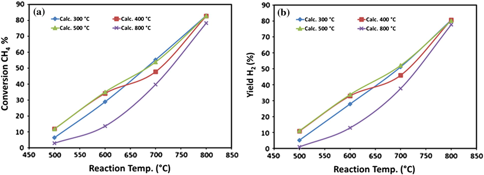
Effect of reaction temperature on (a) CH4 conversions and (b) H2 yield over 20Fe-Al-Imp catalyst series at different calcination temperatures.
It is apparent from the results (Fig. 8) that at 800 °C reaction temperature the catalyst showed stable and high activity with ≈80–85% CH4 conversion for 120 min. However, due to rapid carbon formation over the catalyst surface during reaction at 800 °C, severe plugging of reactor occurred, which built a high backup pressure in the reactor, consequently after 120 min on TOS the reaction had to be stopped at this stage ultimately. In the past several investigators reported their results in terms of methane conversion or hydrogen yield or amount of carbon produced from methane decomposition. For instance, Jin et al. (2013), investigated an activated carbon (AC) supported Fe/Al2O3 catalysts which were prepared by impregnation, the conversion of methane was found to increase with temperature and a conversion of about 35% was obtained at 850 °C when 60% active metals were used. Chesnokov and Chichkan (2009) examined the combination of active metal including Fe for the decomposition of methane. They found the yield of carbon nanofibers 70%Ni–10%Cu–10%Fe/Al2O3 catalyst at 700–750 C was 150–160 g/g while the hydrogen concentration at the reactor outlet exceeded 70 mol%. Pudukudy and Yaakob (2015) reported the work of methane decomposition over Ni, Co and Fe based monometallic catalysts supported on sol gel derived SiO2 microflakes. They found that Fe based catalyst provided less hydrogen yield about 50% but stable for longer time and also multilayer graphene sheets were obtained over the Fe catalysts. Reshetenko et al. (2004) examined the Coprecipitated iron-containing catalysts (Fe-Al2O3 Al2O3, Fe-Co-Al2O3, Fe-Ni-Al2O3) for methane decomposition at moderate temperatures (600–650 °C). They found the multiwall carbon nanotubes and carbon capacity of 145 g/gcat from the bimetallic catalysts containing 50–65 wt.% Fe, 5–10 wt.% Co (or Ni) and 25–40 wt.% Al2O3. Chen et al. (2009) investigated the Influence of calcination temperatures of Feitknecht compound precursor on the structure of Ni–Al2O3 catalyst and the corresponding catalytic activity in methane decomposition to hydrogen and carbon nanofibers. The catalysts were calcined at temperatures of 573, 723, 873 and 1023 K. They found the catalyst calcined at 723 K, produced the highest carbon amount 88 mgC mgNi1 after 320 min.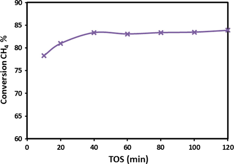
Variations of CH4 conversions over 20Fe-Al-Imp catalyst at 800 °C calcination temperature on TOS at 800 °C.
It is clear from this literature, the performance enhancement in terms of methane conversion and hydrogen yield of the catalysts used in this investigation.
The thermo-gravimetric analysis (TGA) measurements were performed on spent catalysts to obtain quantitative information on the other product of CDM, i.e., carbon as shown in Figs. 9a and 9b. The observed weight loss from the spent catalysts is due to the combustion/gasification of carbon formed on the samples during CDM reaction. In agreement with the catalytic activity, results that are in the case of 20Fe-Al-CP catalyst series (Fig. 9a), among all calcination temperatures, the highest weight loss (49.5%) was observed for catalyst with 500 °C calcination temperature. This catalyst also showed the most activity (Fig. 5). Similarly, in the case of 20Fe-Al-Imp catalyst series (Fig. 9b), the extent of weight loss is quite high (28.5%) in case of catalyst calcined at 500 °C.
TGA patterns for 20Fe-Al-CP spent catalysts at different calcination temperatures.
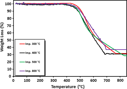
TGA patterns for 20Fe-Al-Imp spent catalysts at different calcination temperatures.
The results of carbon yield as grams of carbon produced per gram of catalyst per mole of methane converted, at different calcination temperatures, obtained over 20Fe-Al-CP, and 20Fe-Al-Imp catalysts series are presented in Fig. S2a and b respectively. It is evident from the results that as compared to 20Fe-Al-Imp catalysts series, the 20Fe-Al-CP catalyst series produced better carbon yield per mole of methane converted. For instance, in the case of 20Fe-Al-CP catalyst series, among all calcination temperatures, the catalyst with 400 °C calcination presented the highest carbon yield (26.82 gC/gcat moles CH4 converted), which in fact, is the carbon that completely covered the active metal surface and deactivated the catalyst. Therefore, all deactivated 20Fe-Al-CP catalysts exhibited more carbon per mole of methane converted. Conversely for 20Fe-Al-Imp catalyst series, no deactivation was observed over all catalysts, so carbon yield as high as 9.52 (gC/gcat. moles CH4 converted) was attained over 20Fe-Al-Imp catalyst calcined at 500 °C.
It has been reported in the literature that different types of the carbons such as amorphous, carbon nanofibers or nanotubes, could be formed during CDM process. On the basis of their thermal stability, these different types of carbons are gasified at a certain range of temperatures, under the oxidative atmosphere. Generally, the amorphous type of carbon is oxidized at temperature <400 °C, whereas the oxidation of ordered nano-structured carbon fibers occurred at temperature >550 °C (Saraswat and Pant, 2013).
For Fe-Al-Imp spent catalysts, the in-depth study of morphology of deposited carbon after CDM reaction was carried out by FESEM and TEM analysis. Fig. 10 displays the FESEM micrographs of Fe-Al-Imp spent catalyst. It is apparent from results that this catalyst resulted in the formation of carbon nanofibers, with typical outer diameters of 30–70 nm. Due to the interweaving of carbon nanofilaments, it remains very tough to estimate the exact length of these nanofibers from FESEM images. Nevertheless, their length varies up to micrometer range. TEM micrographs of the spent Fe-Al-CP catalysts calcined at 500 and 800 °C and Fe-Al-Imp catalyst calcined at 500 °C after decomposition reaction, to study the morphology of carbon formed, are shown in Fig. 11. It is interesting to note that carbon nanofilaments, in case of Fe-Al-Imp catalyst, carry active metal particles at their tips and these filaments grow in size similar to active metal size. However, in the case of co-precipitated catalysts active Fe metal is entrapped in the nano-filaments. Accordingly, the catalysts prepared by impregnation, continue stable activity with TOS whereas catalysts prepared by co-precipitation show loss in activity due to non-availability of Fe metal particles for reaction. In both cases we observe the formation of tubular carbon nanofibers, but the particle of Fe is much smaller in the case of co-precipitated catalysts. This may be the reason for their entrapment in the carbon crystalline matrix and deactivation.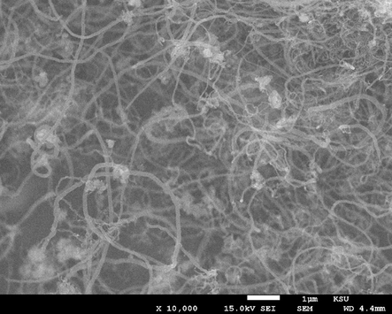
FESEM image of the carbon nanofibers formed over Fe-Al-Imp spent catalyst at different magnifications.
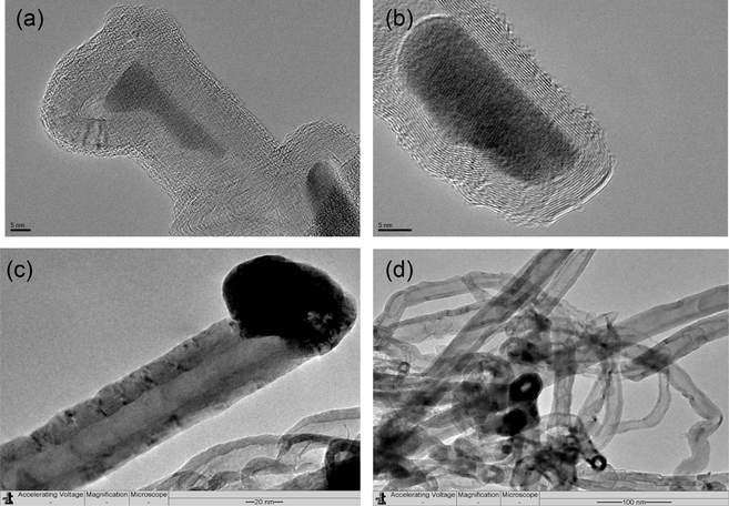
TEM images of the carbon nanofibers formed over (a) Fe-Al-Imp calcined at 500 °C; (b) Fe-Al-CP spent catalyst calcined at 500 °C; (c and d) Fe-Al-CP spent catalysts calcined at 800 °C.
4 Conclusions
Alumina supported Fe catalysts are efficient systems for the catalytic methane decomposition to make COx-free hydrogen and carbon. The nature of the iron oxide precursor from which the catalytic active site is generated via reduction has a strong influence on the catalyst stability and hydrogen yields. The results in the study indicate that iron oxide precursors where Fe is present in 2+ state may favor the formation of catalytically active species via reduction. A maximum methane conversion of 65% and hydrogen yield of 62% obtained over 20Fe-Al-Imp catalyst calcined at 500 °C makes it an efficient system. Carbon formed during the reaction manifests as nanofibers. Larger iron particles formed via impregnation stay outside the carbon fibers and provide continued activity.
Acknowledgments
The authors thankfully acknowledge their appreciation to King Abdulaziz City for Science and Technology (KACST) for funding the work through the research project # AT-34-4.
References
- Hydrogen production by methane decomposition: a review. Int. J. Hydrogen Energy. 2010;35:1160-1190.
- [Google Scholar]
- Effects of calcination and activation temperature on dry reforming catalysts. J. Saudi Chem. Soc.. 2012;16:55-61.
- [Google Scholar]
- Review of methane catalytic cracking for hydrogen production. Int. J. Hydrogen Energy. 2011;36:2904-2935.
- [Google Scholar]
- Catalytic decomposition of CH4 over NiO-Al2O3-SiO2 catalysts: influence of catalyst preparation conditions on the production of H2. Int. J. Hydrogen Energy. 2008;33:4809-4818.
- [Google Scholar]
- Coprecipitated Ni-alumina and Ni-Cu-alumina catalysts of methane decomposition and carbon deposition. II. Evolution of the catalysts in reaction. Appl. Catal., A. 1996;141:117-129.
- [Google Scholar]
- Hydrogen production via methane decomposition over Al2O3–TiO2 binary oxides supported Ni catalysts: effect of Ti content on the catalytic efficiency. Fuel. 2014;129:68-77.
- [Google Scholar]
- Potential importance o f hydrogen as a future solution to environmental and transportation problems. Int. J. Hydrogen Energy. 2008;33:4013-4029.
- [Google Scholar]
- Carbon monoxide poisoning of proton exchange membrane fuel cells. Int. J. Energy Res.. 2001;25:695-713.
- [Google Scholar]
- Influence of calcination temperatures of Feitknecht compound precursor on the structure of Ni–Al2O3 catalyst and the corresponding catalytic activity in methane decomposition to hydrogen and carbon nanofibers. Appl. Catal., A: Gen.. 2009;362:1-7.
- [Google Scholar]
- Production of hydrogen by methane catalytic decomposition over Ni–Cu–Fe/Al2O3 catalyst. Int. J. Hydrogen Energy. 2009;34:2979-2985.
- [Google Scholar]
- Hydrogen production by catalytic partial oxidation of methane over staged Pd/Rh coated monoliths: spatially resolved concentration and temperature profiles. Int. J. Hydrogen Energy. 2014;39:17998-18004.
- [Google Scholar]
- Hydrogen and fuel cells: towards a sustainable energy future. Energy Policy. 2008;36:4356-4362.
- [Google Scholar]
- Non-thermal plasma-catalytic decomposition of volatile organic compounds using alumina supported metal oxide nanoparticles. Surf. Coat. Technol.. 2014;259:12-19.
- [Google Scholar]
- Direct nonoxidative conversion of methane to ethylene, aromatics, and hydrogen. Sci. Mag.. 2014;344:616-619.
- [Google Scholar]
- Industrial Catalysis: A Practical Approach (second ed.). Weinheim: Wiley-VCH; 2006.
- Co-production of graphene sheets and hydrogen by decomposition of methane using cobalt based catalysts. Energy Environ. Sci.. 2011;4:778-783.
- [Google Scholar]
- Methane decomposition over Ni/γ-Al2O3promoted by La2O3and CeO2. J. Nat. Gas Chem.. 2003;12:183-188.
- [Google Scholar]
- Preparation of activated carbon supported Fe–Al2O3 catalyst and its application for hydrogen production by catalytic methane decomposition. Int. J. Hydrogen Energy. 2013;38:10373-10380.
- [Google Scholar]
- Reduction behavior of iron oxides in hydrogen and carbon monoxide atmospheres. Appl. Catal., A: Gen.. 2007;326:17-27.
- [Google Scholar]
- Process integration for energy and water saving, increasing efficiency and reducing environmental impact. Appl. Therm. Eng.. 2010;3:2265-2269.
- [Google Scholar]
- Catalytic routes towards single wall carbon nanotubes. Catal. Rev. Sci. Eng.. 2007;49:341-405.
- [Google Scholar]
- Methane decomposition to COx-free hydrogen and nano-carbon material on group 8–10 base metal catalysts: a review. Catal. Today. 2011;162:1-48.
- [Google Scholar]
- Catalytic growth of carbon fibers from methane on a nickel-alumina composite prepared from Feiknecht compound precursor. Appl. Catal., A. 1997;163:45-57.
- [Google Scholar]
- Decomposition of methane over unsupported porousnickel and alloy catalyst. Appl. Catal., B. 2013;132–133:469-478.
- [Google Scholar]
- Life cycle cost analysis of fuel cell based cogeneration system for residential application in Malaysia. Renew. Sustain. Energy Rev.. 2011;15:416-426.
- [Google Scholar]
- Sustainable energy in Africa: a comprehensive data and policies review. Renew. Sustain. Energy Rev.. 2014;37:656-686.
- [Google Scholar]
- Carbon emissions, energy consumption and output: a threshold analysis on the causal dynamics in emerging African economies. Energy Policy. 2014;70:172-182.
- [Google Scholar]
- Catalytic oxidative steam reforming of bio-ethanol for hydrogen production over Rh promoted Ni/CeO2–ZrO2 catalyst. Int. J. Hydrogen Energy. 2015;40:2529-2544.
- [Google Scholar]
- Green path from fossil-based to hydrogen economy: an overview of carbon-neutral technologies. Int. J. Hydrogen Energy. 2008;33:6804-6839.
- [Google Scholar]
- Hydrogen production reactions from carbon feedstocks: fossil fuels and biomass. Chem. Rev.. 2007;107:3952-3991.
- [Google Scholar]
- Production of pure hydrogen by cyclic decomposition of methane and oxidative elimination of carbon nanofibers on supported-Ni-based catalysts. Appl. Catal., A: Gen.. 2004;273:113-124.
- [Google Scholar]
- Kinetics of reduction of iron oxides by H2: Part I: low temperature reduction of hematite. Thermochim. Acta. 2006;447:89-100.
- [Google Scholar]
- Kinetics of reduction of iron oxides by H2: Part II. Low temperature reduction of magnetite. Thermochim. Acta. 2007;456:75-88.
- [Google Scholar]
- High temperature iron-based catalysts for hydrogen and nanostructured carbon production by methane decomposition. Int. J. Hydrogen Energy. 2011;36:7832-7843.
- [Google Scholar]
- Direct decomposition of methane over SBA-15 supported Ni, Co and Fe based bimetallic catalysts. Appl. Surf. Sci.. 2015;330:418-430.
- [Google Scholar]
- Methane decomposition over Ni, Co and Fe based monometallic catalysts supported on sol gel derived SiO2 microflakes. Chem. Eng. J.. 2015;262:1009-1021.
- [Google Scholar]
- Coprecipitated iron-containing catalysts (Fe-Al2O3, Fe-Co-Al2O3, Fe-Ni-Al2O3) for methane decomposition at moderate temperatures: Part II. Evolution of the catalysts in reaction. Appl. Catal., A: Gen.. 2004;270:87-99.
- [Google Scholar]
- Synthesis of hydrogen and carbon nanotubes over copper promoted Ni/SiO2 catalyst by thermocatalytic decomposition of methane. J. Nat. Gas Sci. Eng.. 2013;13:52-59.
- [Google Scholar]
- H2 from steam reforming of ethanol at low temperature over Ni/Y2O3, Ni/La2O3 and Ni/Al2O3 catalysts for fuel-cell application. Int. J. Hydrogen Energy. 2005;30:437-445.
- [Google Scholar]
- Syngas production via dry reforming of methane over Ni-based nanocatalyst over various supports of clinoptilolite, ceria and alumina. J. Nat. Gas Sci. Eng.. 2015;23:16-25.
- [Google Scholar]
- Hydrogen and multiwall carbon nanotubes production by catalytic decomposition of methane: thermogravimetric analysis and scaling-up of Fe–Mo catalysts. Int. J. Hydrogen Energy. 2014;39:3698-3709.
- [Google Scholar]
- Hydrogen production by catalytic decomposition of methane using a Fe-based catalyst in a fluidized bed reactor. J. Nat. Gas Chem.. 2012;21:367-373.
- [Google Scholar]
- Energy and water interactions: implications for industry. Curr. Opin. Chem. Eng.. 2014;5:15-21.
- [Google Scholar]
- Effective synthesis of carbon nanotubes via catalytic decomposition of methane: Influence of calcination temperature on metal–support interaction of Co–Mo/MgO catalyst. J. Phys. Chem. Solids. 2013;74:1553-1559.
- [Google Scholar]
Appendix A
Supplementary material
Supplementary data associated with this article can be found, in the online version, at http://dx.doi.org/10.1016/j.arabjc.2016.06.012.
Appendix A
Supplementary material
Supplementary data 1
Supplementary data 1


